S-line VA16 User manual

CONTENTS
1.Safetyinformation .
2. Description .
3.Operating instruction
4. Specifications
5. Battery&Fusereplacement ...
6.Accessory ..
1
5
7
13
17
19

1. SAFETYINFORMATION
Thismultimeterhasbeendesignedaccordingto
IEC-1010 concerningelectronicmeasuring
instrumentswithanovervoltagecategory
CAT 1000V,CATⅢ600Vand pollution2.
Withproperuseand care,thedigitalmultimeter
will giveyou yearsofsatisfactoryservice.
Followallsafetyand operatinginstructionsto
ensurethat themeterisusedsafelyandiskept in
good operating condition.
1.1PRELIMINARY
1.1.1Whenusingthemeter,theusermust
observeallnormalsafetyrulesconcerning:
●Protectionagainstthedangerofelectricalattack
●Protectionof themeteragainst misuse
WARNING
Toensuresafeoperation,and inorderto
exploittothefull functionalityofthemeter,
pleasefollowthedirectionsinthissection
carefully.
-1-

1.1.2Whenthemeterisdelivered,check ifithas
beendamagedintransit.
1.1.3Whenharshpreservation orshipping
conditionscaused,inspectandconfirmthismeter
withoutdelay.
1.1.4Test leadsmustbeingood condition.Before
using, verifythattheinsulationon test leadsisnot
damagedand/ortheleadswireisnotexposed.
1.1.5Full compliancewithsafetystandardscanbe
guaranteedonlyidusedwithtestleadssupplied. If
necessary,theymustbereplaced withthesame
modelorthesameclass.
1.2DURING USE
1.2.1Neverexceedtheprotection limitvalues
indicatedinspecificationsforeachrangeof
measurement.
1.2.2Whenthemeterislinkedtomeasurement
circuit, donottouchunusedterminals.
1.2.3Whenthevaluescaletobemeasuredis
unknownbeforehand, settherangeselectoratthe
highestposition.
1.2.4Beforerotating therangeselectortochange
functions,disconnecttestleadsfromthecircuit
-2-

undertest.
1.2.5WhencarryingoutmeasurementsonTVor
switching powercircuits,alwaysrememberthat
theremaybehighamplitudevoltagespulsesat
test pointswhichcandamagethemeter.
1.2.6Neverperformresistancemeasurementson
livecircuits.
1.2.7Always becarefulwhenworking with
voltagesabove60Vdcor30Vacrms.Keep
fingersbehindtheprobebarrierswhilemeasuring.
1.3SYMBOLS
Importantsafetyinformation,refertothe
operating manual.
ConformstoEuropean UnionDirective
Earthground
1.4MAINTENANCE
1.4.1Pleasedonotattempttoadjustorrepairthe
meterbyremoving therearcasewhilevoltageis
being applied.Atechnician who fullyunderstands
dangerinvolvedshouldonlycarryoutsuch
actions.
1.4.2Beforeopening thecaseof themeter,always
-3-

disconnecttestleadsfromall sourcesofelectric
current.
1.4.3Toavoidthewrongreading causing
electricityattack,whenthemeterdisplays“ ”,
you mustchangethebattery.
1.4.4Forcontinueprotection againstfire,replace
fuseonlywiththespecified voltageandcurrent
ratings:F200mA/250V(quickacting).
1.4.5Donotuseabrasivesorsolventsonthe
meter,useadampclothand milddetergentonly.
1.4.6ALWAYS setthepowerswitchtotheOFF
position whenthemeterisnotinuse.
1.4.7If themeteristobestored foralongperiod
oftime,thebatteriesshouldberemovedtoprevent
damagetotheunit.
-4-

2. DESCRIPTION
The3in1digitalmulti-testerhasbeendesignedto
combinethefunctionsofDigitalMultimeter,
TelephoneLineTesterand NetworkCableTester.
●DC voltagemeasurement,5rangesfrom200mV
to1000V
●ACvoltagemeasurement,5rangesfrom200mV
to700V
●DC/ACcurrentmeasurement,5rangesfrom
200µAto10A
●Resistancemeasurement, 7rangesfrom200Ω
to200MΩ
●Diodetest
●Audiblecontinuitytest
●Batterytest:1.5/6/9V
●TelephoneLinetest (RJ11)
●NetworkCabletest(RJ45)
Namesofcomponents
1RJ11testjack
2RJ45 testjack
3Dataholdkey(onlyformultimeter)
4AC/DC switchkey
5-
8input jacks
-5-

9RJ45 jack(Remote)
10Function/rangeselectrotaryswitch
11Cabletestkey/Resent
12Back lightkey
13LCD display
VCOMA10A
12
11
10
9
8765
3
42
1
13
-6-

3.OPERATINGINSTRUCTION
3.1MEASURINGVOLTAGE
3.1.1Connecttheblack testlead totheCOMjack
and theredtest lead totheV/Ωjack.
3.1.2Settherotaryswitchat thedesired “V”range
positionandconnecttestleadsacross thesource
orloadundermeasurement.
3.1.3Putdownthe"AC/DC" whenmeasuring the
voltage.MeterwillbetransformedbetweenDC
and ACrange.
3.1.4If youneeddataholdwhenmeasuring,you
can puton “HOLD”,itwillholdthereading;ifyou
putthebutton again,dataholdwillnotcontinue.
3.1.5Whenonlythefigure“1”isdisplayed,it
indicatesoverrangesituationandthehigherrange
hastobeselected.
3.2MEASURINGCURRENT
3.2.1Connecttheblack testlead totheCOMjack
and theredtestlead totheAjack foramaximum
of200mA.Foramaximumof10A,movethered
lead tothe10Ajack.
3.2.2Settherotaryswitchatdesired “A”range
-7-

position andconnecttestleadsinserieswiththe
loadundermeasurement.
3.2.3Putdownthe"AC/DC" whenmeasuring the
current. Meterwill betransformed betweenDC
and ACrange.
3.2.4If youneeddataholdwhenmeasuring,you
can puton “HOLD”,itwillholdthereading;ifyou
putthebutton again,dataholdwillnotcontinue.
3.2.5Whenonlythefigure“1”isdisplayed,it
indicatesoverrangesituationandthehigherrange
hastobeselected.
3.3TESTINGDIODE/CONTINUITY
3.3.1Connecttheblack testlead totheCOMjack
and theredtestlead totheV/Ωjack.(NOTE: The
polarityof redlead connection ispositive“+”)
3.3.2Settherotaryswitchat positionand
connecttheredlead totheanode,theblacklead
tothecathodeofthediodeundertesting.The
meterwillshowtheapprox.Forwardvoltagedrop
ofthediode.Ifthelead connectionisreversed,
onlyfigure“1”willbedisplayed.Ifcontinuityexists
(i.e., resistanceless than about70Ω),built in
buzzerwill sound.
-8-

3.4MEASURINGRESISTANCE
3.4.1Connecttheblack testlead totheCOMjack
and theredtestlead totheV/Ωjack.(NOTE:The
polarityof redlead connection ispositive“+”)
3.4.2Settherotaryswitchatdesired Ωrange
position andconnecttestleadsacross the
resistanceundermeasurement. Read LCD
display.
NOTE:
1.Forresistanceabove1MΩ,themetermaytake
afewsecondstostabilizereading.
2.Whentheinputisnotconnected,i.e.atopen
circuit,thefigure “1”will bedisplayedforthe
overrangecondition.
3.Whenchecking in-circuitresistance,besure
thecircuit undertesthasallpowerremovedandall
capacitorsarefulldischarged.
4.At200MΩrangedisplayis10countswhen test
leadsareshorted.Thesecountshavetobe
subtractedfrommeasuringresults.Forexample,
whenmeasuring100MΩresistance,thereading
will be101.0andthecorrectmeasuringresult
shouldbe101.0 1.0=100.0MΩ.
-9-

3.5TESTINGBATTERY
3.5.1Connecttheblack testlead totheCOMjack
and theredtest lead totheV/Ωjack.
3.5.2Settherotaryswitchatthedesired “BAT”
rangepositionand connecttestleadsacrossthe
battery.
Position 1.5v 6v 9v
load 27Ω68Ω100Ω
3.6TESTINGTelephoneLine(RJ11)
3.6.1ConnecttheRJ11testjacktooneend ofthe
telephonelinetobetested.
3.6.2ConnecttheUAX(TelephoneUnitAutomatic
Exchange) totheotherend oftheline.
3.6.3Push “TEST”button toperformtest.
3.7TESTINGNetworkCable(RJ45)
●ThenetworktesterissuitableforT168A, T568B,
10Base-Tand TokenRing.
TheNetworkCableTesterwillcheckafault
CAUTION!DONOTuseon thecircuitsasit
maydamagethetester.
-10-

conditionintheabovedescendingorderbefore
detectingotherfaultconditions. Thedetectionand
indicationofthepresenceofafaultishandledon a
“one-per-test”basis.Onceafaultiscorrected,itis
recommendedthecablebetestedagainforother
faults.
OPEN Thereisno “OPEN”indication.Atypical
cablemayhave2,3,or4pairs.OPENSare
displayedasanunlitsymbol.Theuserwill
determineifapairispresentandcontinuousor
OPENbycomparingtheilluminated symboltothe
expectednumberof pairsthatshouldbegood.
SHO. Ashortcircuitconditionexists(see Fig.1).
MIS. Indicatestheimproperassignmentof
individualwirepairstopinsforthewiringschemes
tested(see Fig.2).
REV. Reversewiring meansthepinforonewire
inapairisconnectedtotheoppositepinforthe
pairintheremotejack(see Fig.3).
SPL. Splitpairsoccurwhenthetip(positive
conductor) andring(negativeconductor)oftwo
twistedpairsareinterchanged(see Fig.4).
-11-

3.7.1ConnecttheRJ45 testjack tooneend ofthe
cabletobetested.
3.7.2Connecttheremoteunittotheotherend of
thecable.
3.7.3PushTESTbutton toperformtest. Example:
TheCableFaultisaSHORTonPair1-2andPair
3-6, theLCD statuswill beasfollows:
Pair1-2,Pair3-6,Pair4-5,Pair7-8,SHIEand
SHO willdisplayat thesametime.
3.7.4PushTESTbuttonagain,Pair1-2,Pair3-6
and SHOwilldisplay.ContinuetoPushTEST
button, thenext pairswilldisplay.
Fig.4 SPLITPAIRS
Fig.3 REVERSED
Fig.2 MISWIRE
Fig.1 SHORT
Fig.5 RIGHT(PASS)
1
2
3
6
4
5
7
8
1
2
3
6
4
5
7
8
1
2
3
6
4
5
7
8
1
2
3
6
4
5
7
8
1
2
3
6
4
5
7
8
1
2
3
6
4
5
7
8
1
2
3
6
4
5
7
8
1
2
3
6
4
5
7
8
1
2
3
6
4
5
7
8
1
2
3
6
4
5
7
8
-12-
4. SPECIFICATIONS
Accuracy isspecifiedforaperiodoneyearafter
calibrationand at18 ºCto28 ºC(64 ºFto82 ºF)
withrelativehumidityto80 %.
4.1GENERAL
4.2VOLTAGE DC VOLTAGE
Range
Resolution
Accuracy
200mV
0.1mV
2V 1mV
20V 10mV
200V 100mV
±0.8 %ofrdg ±2digits
1000V 1V ±1.2 %ofrdg ±3digits
MAXIMUM VOLTAGE 1000VDC or 700VAC
FUSE PROTECTION mA: F 200mA/250V10A: no
POWER SUPPLY 9Vbattery,NEDA1604or 6F22
OPERATINGTEMPERATURE
0 ºCto40 ºC (32 ºFto104 ºF)
STORAGE TEMPERATURE 10 ºCto50 ºC (14 ºFto122 ºF)
DIMENSION 185×85×44 mm
WEIGHT 360g (including battery )
-13-

ACVOLTAGE
Range
Resolution
Accuracy
200mV
0.1mV ±1.2 %ofrdg ±3digits
2V 1mV
20V 10mV
200V 100mV ±0.8 %ofrdg ±3digits
700V 1V ±1.2 %ofrdg ±5digits
InputImpedance: 10MΩ
Frequency Range: 40Hzto400Hz(forAC)
Response:Average,calibratedinrmsofsine
wave
4.3CURRENT DC CURRENT
Range Resolution
Accuracy
200µA 0.1µA
2mA 1µA
20mA 10µA
±0.8 %ofrdg ±3digits
200mA 100µA ±1.5 %ofrdg ±2digits
10A 10mA ±2.0 %ofrdg ±5digits
-14-

ACCURRENT
Range Resolution
Accuracy
200µA 0.1µA ±2.0 %ofrdg ±3digits
2mA 1µA
20mA 10µA ±1.0 %ofrdg ±3digits
200mA 100µA ±1.8 %ofrdg ±3digits
10A 10mA ±3.0 %ofrdg ±5digits
Overload Protection:F200mA/250Vfusefor
200µAto200mAranges
Frequency Range: 40Hzto400Hz(forAC)
Response:Average,Calibratedinrmsofsine
wave
4.4RESISTANCE
Range Resolution
Accuracy
200Ω0.1Ω±0.8 %ofrdg ±3digits
2KΩ1Ω±0.8 %ofrdg ±2digit
20KΩ10Ω±0.8 %ofrdg ±2digit
200KΩ100Ω±0.8 %ofrdg ±2digit
2MΩ1KΩ±0.8 %ofrdg ±2digit
20MΩ10KΩ±1.0 %ofrdg ±2digit
200MΩ
100KΩ±5.0 %of(rdg-10digits)
±10digits
MaximumOpenCircuitVoltage:700mV(3Vfor
-15-

200MΩrange).
Note: On200MΩrange, if shortinput,displaywill
read 1MΩ,this1MΩshouldbesubtractedfrom
measurementresults.
Overload Protection:250Vdcor250Vacrms
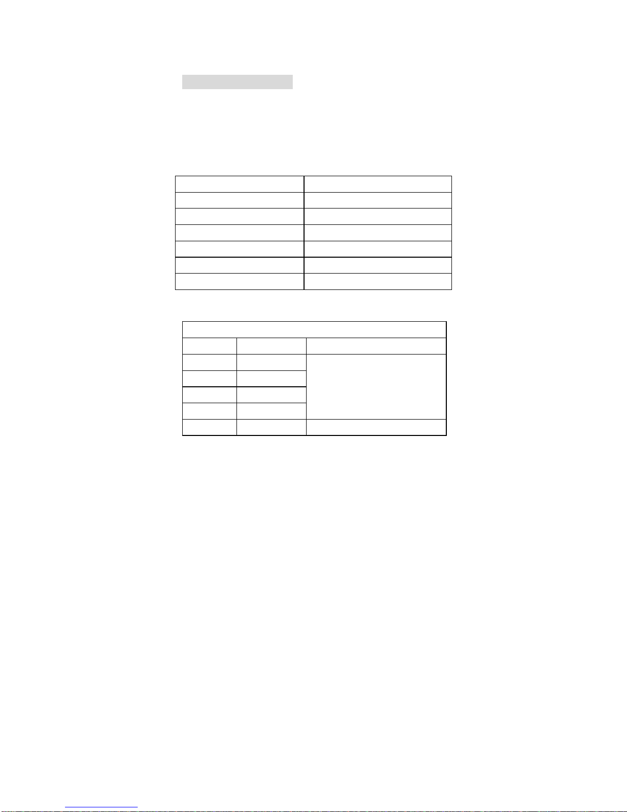
4.5DIODE/CONTINUTY
Range Description
Diode Showstheapproximateforward
voltagedrop
Continuity
Built –inbuzzerwillsound,ifthe
resistanceundertestisless than
about70Ω
Overload Protection:250Vdcor250Vacrms
-16-

5. BATTERY &FUSEREPLACEMENT
Ifthesign“”appearson theLCDdisplay,it
indicatesthatbatteryshouldbereplaced.
Removescrewson thebackcoverandopen
thecase(see therightphoto).Replacethe
exhaustedbatterywithanewone.
Fuserarelyneedreplacementandblowalmost
alwaysasaresultof theoperator’serror. Open
thecaseasmentionedabove,andthentake
thePCBoutfromthefrontcover.Replacethe
blownfusewithsameratings.
-17-

WARNING
Beforeattemptingtoopenthecase,besurethat
testleadshavebeendisconnectedfrom
measurementcircuitstoavoidelectricshock
hazard.
Forprotectionagainstfire,replacefuseonlywith
specifiedratings: F200mA/250V
-18-

6. ACCESSORIES
•
Test Leads:ElectricRatings
1000V10A oneset
‚
Battery:9V, NEDA
1604 or6F22 onepiece
OperatingManual onepiece
-19
Table of contents


