Overload protection: 250V DC/250Vrms AC
3. MEASURING INSTRUCTION
3.1 DC Voltage measurement
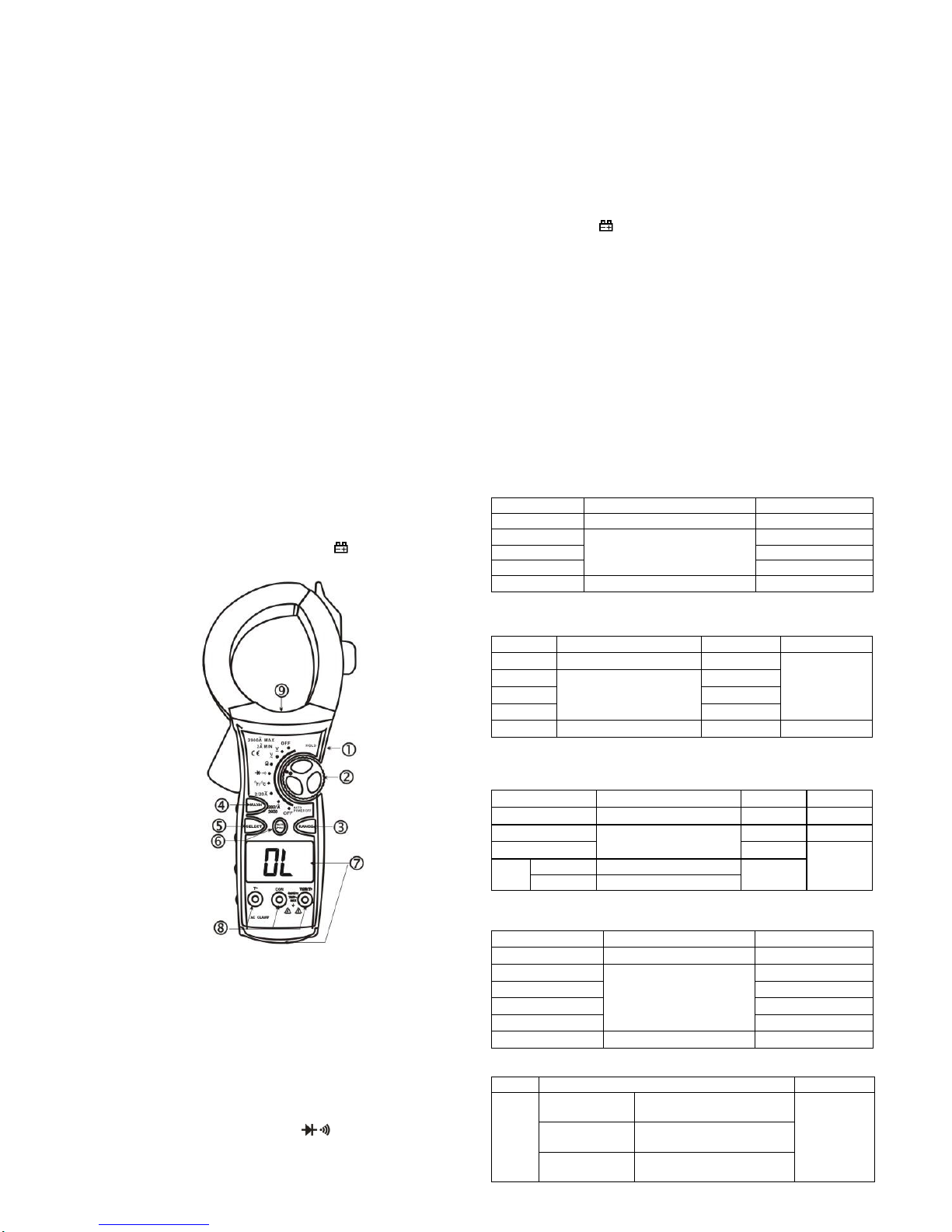
1) Connect the black test lead to "COM" socket and red test lead
to the "VΩT+" socket.
2) Set the selector switch to desired " " position and connect the
probes across the source or load under measurement.
3) Read the result from the LCD panel.
3.2 AC Voltage measurement
1) Connect the black test lead to "COM" socket and red test lead
to the " VΩT+" socket.
2) Set the selector switch to desired " " position and connect
the probes across the source or load undermeasurement.
3) Read the result from the LCD panel.
3.3 AC Current measurement
1) Set selector switch to desired " " position.
2) Open the clamp by pressing the jaw-opening handle and insert
the cable (one cable only) to be measured into the jaw.
3) Close the clamp and get the reading from the LCD panel.
Note:
a) Before this measurement, disconnect the test lead with the
meter for safety.
b) In same occasion that the reading is hard to read, push the
HOLD button and read the result later.
3)When in measuring voltage can click on the "range" key for "mV"
and "V" conversion
3.4Resistance measurement
1) Connect the black test lead to "COM" socket and red test lead
to the " VΩT+" socket.
2) Set the selector switch to desired "Ω" position, the present
function is resistance measurement.
3) Connect the probes across circuit to be tested.
4) Read the result from the LCD panel.
Caution: Ensure that the circuit to be tested is "dead". Max. input
over-load: 250V rms<10sec
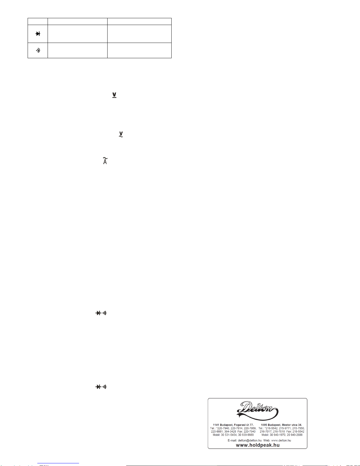
3.5 Diode test
1) Connect the black test lead to "COM" socket and red test
lead to the " VΩT+" socket.
2) Set the selector switch to " " position.
3) Push "SELECT" to select diode test.
4) Connect the black and red test probe to the cathode (-) and
anode (+) ends of diode to be tested respectively, read the forward
voltage drop (junction) value from the display. If reverse connected
the probes to diode, display shows over-load.
Caution: Ensure that the circuit to be tested is "dead". Max .input
over-load: 250V rms<10sec
3.6 Audible continuity test
1) Connect the black test lead to "COM" socket and red test lead
to the " VΩT+" socket.
2) Set the selector switch to " " position.
3) Push "SELECT" to select audible continuity test.
4) Connect the probes across circuit to be tested, the beeper
sounds continuously if the resistance is less than approx. 70Ω.
Caution: Ensure that the circuit to be tested is "dead". Max .input
over-load: 250V rms<10sec
3.9 Temperature measurement
1) Connect the black test lead of the sensor to "T-" socket and
the red test lead to the "T+" socket.
2) Set the selector switch to "℃/℉" position.
3) Put the sensor probe into the temperature field under
measurement.
4) Read the result from the LCD panel.
Max .input over-load: 250V rms<10sec
A. The temperature function shows the random number at
ordinary times, must insert the thermocouple in temperature test
hole while examining temperature.
B. This meter in closure WRNM-010 type contact thermocouple
limit temperature is 250 ℃(300 ℃shortly ) ;
C. Please don't change the thermocouple at will , otherwise we
can't guarantee to measure accuracy ;
D. Please don’t importing the voltage in the temperature function.
3.10 Auto/Manual Range Control
The auto range mode is a convenient function, but it might be
faster to manually set the range when you measure values that
you know to be within a certain range .To select manual range
control, repeatedly press "RANGE" until the display shows
the desired range. The range steps upward as you press "RANGE".
But when you press "RANGE" for more than 2 seconds, then it can
go to auto range mode.
Caution: While suing the manual range control, if "OL" appears on
the display and you hear an intermittent tone, immediately set
RANGE to a higher range.
4. CARE AND MAINTENANCE
4.1 CARING FOR YOUR MULTIMETER
Your Digital Multi meter is an example of superior design and
craftsmanship. The following suggestions will help you care for the
multi meter so you can enjoy it for years.
1) Keep the multi meter dry. If it gets wet, wipe it dry immediately.
Liquids can contain minerals that can corrode electronic circuits.
2) Use and store the multi meter only in normal temperature
environments. Temperature extremes can shorten the life of electronic
devices, damagebatteries and distort or melt plastic parts.
3) Handle the multi meter gently and carefully. Dropping it can
damage the circuit boards and cause and can accuse the multi
meter to work improperly.
4) When take current measurement, keep the cable at the center
of the clamp will get more accurate test result.
5) Keep the multi meter away from dust and dirt, which can cause
premature wear of parts.
6) Wipe the multi meter with a damp cloth occasionally to keep it
looking new. Do not use harsh chemicals, cleaning solvents, or
strong detergents to clean the multi meter.
7) Use only fresh batteries of the required size and type. Always
remove old or weak batteries. They can leak chemicals that
destroy electronic circuits.
8) Please take out the battery when not using for a long time.
4.2 9Volt battery replacement
1) Ensure the instrument is not connected to any extreme circuit.
Set the selector switch to "OFF" position and remove the test leads
from the terminals.
2) Open the cover of the battery cabinet by a screwdriver.
3) Replace the old batteries with the same type batteries.
4) Close the battery cabinet cover and fasten the screw.