SAA Asia Limited SND-7080 User manual

NETWORK CAMERA
Quick Guide SND-7080
English
PT01-000152A-SND-7080N-QG_ENGLIS1 1 2011-03-24 오후 6:10:48

2_ English2
WHAT’S INCLUDED
Please check if your camera and accessories are all included in the product package.
Appearance Item Name Quantity Description
User Manual,
Installer S/W DVD,
CMS S/W DVD
2
Quick Guide 1
Iron Screw 3 Used for fixing to an iron plate
Cable for the testing
monitor 1Used to test the camera connection to a
portable display device
Dustproof Plate 1 Preventing dust inflow
PT01-000152A-SND-7080N-QG_ENGLIS2 2 2011-03-24 오후 6:10:48

English
English _3
AT A GLANCE
Appearance
Item Description
a
Top cover Case cover used to protect the lens and the main unit.
b
Camera Case Covers the lens and camera body.
c
Power Port Used to plug the power cable.
d
Alarm In /
Out terminals
ARM-IN BLUE : Used to connect the alarm input signal.
ARM-OUT WHITE : Used to connect the alarm output signal.
A-COM GRAY : Common port where the alarm output signal is
connected.
GND YELLOW : Used for earth-grounding.
e
Network Port Used to connect a PoE or LAN cable.
f
Video Out Port Analog video output port. (for installation)
g
Audio In Jack Used to connect to a microphone.
h
Audio Out Jack Used to connect to speakers.
8
PT01-000152A-SND-7080N-QG_ENGLIS3 3 2011-03-24 오후 6:10:48

4_ English4
Inside
Item Description
a
Monitor Out Using the test monitor cable, you can connect to a mobile display for camera
test.
b
Reset Button
Resets the camera settings to the default. Press and hold it for about 5
seconds to turn off the system indicator and restart the system.
J
If you reset the camera, the network settings will be adjusted so that
DHCP can be enabled. If there is no DHCP server in the network, you
must run the IP Installer program to change the basic network settings
such as IP address, Subnet mask, Gateway, etc., before you can
connect to the network.
c
SD Memory Card
Compartment Compartment for the SD memory card.
d
Wiring Cover
If you drill a hole in the wiring cover for wiring,
remove the cover and attach the provided dustproof
plate to it, and arrange the cables through the plate.
The dust-proof plate is to prevent outside dust from
inflow to the wiring compartment.
e
Lock Release
To separate the bracket from the main unit for the installation or to separate
the camera from an installed camera, push this release and turn the main
unit in the marked direction of <UNLOCK>.
PT01-000152A-SND-7080N-QG_ENGLIS4 4 2011-03-24 오후 6:10:51

English
English _5
INSTALLATION
Precautions before installation
Ensure you read out the following instructions before installing the camera:
Select an installation site (ceiling or wall) that can endure at least 5 times of the
camera weight.
Stuck-in or peeled-off cables can cause damage to the product or a fire.
For safety purposes, keep anyone else away from the installation site. And put aside
personal belongings from the site, just in case.
Disassembling
Take the camera body with one hand and take the top
cover with the other hand. Then, turn the cover counter
clockwise to remove it.
Hold down the lock lever in the outer direction as shown
and turn the camera body in the <UNLOCK> direction
(counter clockwise) to remove the bracket from the
body.
If it fails, take the bottom hole of the bracket and turn the
bracket in the <LOCK> direction (clockwise) to remove it.
1.
2.
Top cover
Camera Body
Bracket
Camera Body
PT01-000152A-SND-7080N-QG_ENGLIS5 5 2011-03-24 오후 6:10:53

6_ English6
Installation
Use the provided screws (x3) to fix the bracket to a desired position (ceiling or wall).
Ensure that the <CAMERA FRONT> label on the bracket faces the direction for camera monitoring.
Arrange the cables through the bracket to
the ceiling or wall.
If you drill a hole in the ceiling cover for wiring, press
hard to remove the cover and attach the dust-proof
plate to it, and arrange the cables through the plate.
If you intend to arrange the cables without drilling a
hole, use the empty area opposite to the <CAMERA
FRONT> label side for the wiring purpose.
Mount the camera body onto the bracket.
Align the marking hole of the camera body
with the <CAMERA FRONT> label of the
bracket, and turn the body in the <LOCK>
direction.
Refer to “Adjusting the monitoring direction
for the camera” to adjust the lens in a desired
direction.
Close the top cover.
Fit the top cover into the fixing tips of the camera
body and turn the cover clockwise.
1.
2.
3.
4.
5.
Wiring Cover
PT01-000152A-SND-7080N-QG_ENGLIS6 6 2011-03-24 오후 6:10:54

English
English _7
Adjusting the monitoring direction for the camera
Adjusting the monitoring direction
You can adjust the camera direction only when the camera is fixed on the ceiling.
Where, rotating the camera unit to the left or right is called Pan, adjusting the tilt is called
Tilt, and turning the lens on its axis is called Rotate.
The effective range of pan is a total of 355 degrees.
The effective range of rotation is a total of 355 degrees.
The effective range of tilt is a total of 90 degrees.
In some angles, the top cover may cause cutting some part of the monitoring object.
Do not rotate the focus/zoom lens by force after removing the cover front.
Otherwise, it may cause an incorrect focus due to a motor failure.
Methods of adjustment
After installing the camera, adjust the panning angle in consideration of the
monitoring direction.
When tilting the camera, you should adjust the horizontal angle lest that the image
be displayed reversely.
Adjust the rotation angle to correct the image display position (up/down/left/right).
Rotating means rotation on the basis of the rear lens unit.
Adjust the tilt angle so that the camera faces toward the monitoring object.
❖
-
-
-
J
❖
1.
2.
3.
Panning
Tilting
Lens rotation
Cover Front
PT01-000152A-SND-7080N-QG_ENGLIS7 7 2011-03-24 오후 6:10:54

8_ English8
CONNECTING WITH OTHER DEVICE
Connecting to the monitor
Connect the video out port of the camera to the video input port of the monitor.
In the initial installation of the camera, you can connect the camera to the monitor for checking
the connection status.
You can set the video output type to either NTSC or PAL.
Ethernet Connection
Connect the Ethernet cable to the local network or to the Internet.
Power Supply
Use the screwdriver to connect each line (+, –) of the power cable to the corresponding
power port of the camera.
Be careful not to reverse the polarity when you connect the power cable.
You can also use a router featuring PoE (Power over Ethernet) to supply power to the camera.
If PoE and DC 12V are both applied, this camera will get supplied with power from PoE.
Please make sure the monitor and camera are turned off when connecting them.
M
J
Monitor
Power
Ethernet
Monitor Out
PT01-000152A-SND-7080N-QG_ENGLIS8 8 2011-03-24 오후 6:10:54

English
English _9
Connecting to Audio Input/Output
Connect the AUDIO IN port of the camera with the microphone directly or LINE OUT
port of the amplifier that the microphone is connected to.
Connect the AUDIO OUT port of the camera with the LINE IN port of the speaker.
Check the specifications for audio input.
Audio Codec
G.711 PCM. μ-law 64kbps 8kHz sampling
Full duplex Audio
Audio in
Used for mono signal line input (Max.2.4 Vpp)
Audio out
Used for mono signal line output (Max.2.4 Vpp)
Line out impedance
600Ω
1.
2.
3.
PC
Network
Speaker
Microphone
Amp
Amp
Microphone
Microphone
Speaker
PT01-000152A-SND-7080N-QG_ENGLIS9 9 2011-03-24 오후 6:10:55

10_ English10
IP SETUP
Manual Network Setup
Run <IP Installer_vX.XX.exe> to display the camera search list.
At the initial startup, both [Auto Set] and [Manual Set] will be grayed out.
For cameras found with the IPv6 setting, these buttons will be grayed out as the cameras do not
support this function.
Select a camera in the search list.
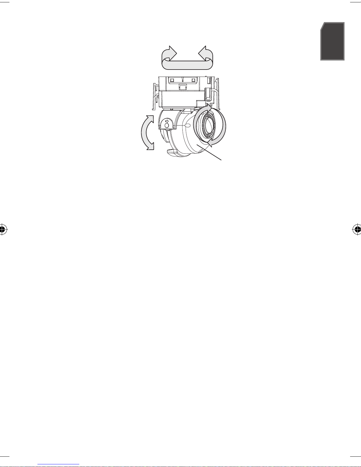
Find the MAC (Ethernet) address
labeled on the rear of the camera.
Both the [Auto Set] and [Manual Set]
buttons will be activated.
Click [Manual Set].
The Manual Setting dialog appears.
The default values of <IP Address>,
<Subnet Mask>, <Gateway>, <HTTP Port> and <VNP Port> of the camera will
be displayed.
In the <Address> pane, provide the
necessary information.
MAC (Ethernet) Address : The MAC
(Ethernet) address of the applicable
camera will be set automatically so
you don't need to input it manually.
You can configure the static IP settings
only if the DHCP checkbox is unchecked.
In the <Port> pane, provide necessary information.
HTTP Port : Used to access the camera using the Internet browser, defaulted to
80. Use the spin button to change the HTTP Port value.
VNP Port : Used to control the video signal transfer, defaulted to 4520.
Enter the password.
This is the login password for the “admin” user who accesses the camera.
The default password is “4321”.
Click [OK].
Manual network setup will be completed.
M
1.
2.
3.
M
4.
5.
6.
PT01-000152A-SND-7080N-QG_ENGLIS10 10 2011-03-24 오후 6:10:55

English
English _11
USING THE LIVE SCREEN
Item Description
a
Monitoring Move to the monitoring screen.
b
Playback Switch to the monitoring screen that plays recording data in the SD memory.
c
Setup Move to the Setup screen.
d
Viewer Screen Displays the Live video on the screen.
e
Alarm Output Activate the Alarm Out port.
f
Audio Display the audio Listen and Talk toggle button on the screen.
g
Hide the alarm
indicator Hides the alarm indicator near the border of the viewer screen.
PT01-000152A-SND-7080N-QG_ENGLIS11 11 2011-03-24 오후 6:10:55

12_ English
12
Item Description
h
Digital zoom You can use the mouse wheel to activate the digital zooming.
i
Screen
Optimization,
Full Screen
Adjust the screen to the optimal size, and display the Full Screen icon on the Live
screen.
j
Capture Saves the snapshot as an image file in the .bmp format.
k
Video Format
You can select a profile type in <Video profile> under the <Audio & Video> setup
menu.
If the “Invalid codec” message is displayed, select a profile type from the profile
list again.
M
If the temperature drops below the operational range, video signal may not be produced. In such
cases, please wait for the video.
Web pages related to playback and setting menus are accessible only by the admin. For other
user accounts, the buttons will be deactivated.
M
PT01-000152A-SND-7080N-QG_ENGLIS12 12 2011-03-24 오후 6:10:55

Samsung Techwin cares for the environment at all product manufacturing stages, and is
taking measures to provide customers with more environmentally friendly products.
The Eco mark represents Samsung Techwin’s devotion to creating environmentally friendly
products, and indicates that the product satisfies the EU RoHS Directive.
PT01-000152A-SND-7080N-QG_ENGLIS13 13 2011-03-24 오후 6:10:55

SALES NETWORK
SAMSUNG TECHWIN CO., LTD.
Samsungtechwin R&D Center, 701, Sampyeong-dong, Bundang-gu, Seongnam-si, Gyeonggi-do, Korea, 463-400
TEL : +82-70-7147-8740~60 FAX : +82-31-8018-3745
SAMSUNG TECHWIN AMERICA Inc.
100 Challenger Rd. Suite 700 Ridgefield Park, NJ 07660
Toll Free : +1-877-213-1222 Direct : +1-201-325-6920
Fax : +1-201-373-0124
www.samsungcctvusa.com
SAMSUNG TECHWIN EUROPE LTD.
Samsung House, 1000 Hillswood Drive, Hillswood Business
Park Chertsey, Surrey, UNITED KINGDOM KT16 OPS
TEL : +44-1932-45-5300 FAX : +44-1932-45-5325
www.samsungtechwin.com
www.samsungsecurity.com
www.samsungipolis.com
PT01-000152A-SND-7080N-QG_ENGLIS14 14 2011-03-24 오후 6:10:55

CAMÉRA RÉSEAU
Guide de prise en main rapide SND-7080
Français
PT01-000152A-SND-7080N-QG_FRENCH1 1 2011-03-24 오후 7:32:15

2_ Français2
CONTENU
Veuillez vérifier si votre caméra et l’ensemble de ses accessoires sont contenus dans l’emballage
du produit.
Apparence Nom de l'élément Quantité Description
Manuel d’utilisation, DVD
du logiciel Installer, DVD
du logiciel CMS
2
Guide de prise en main
rapide 1
Vis métallique 3 Permet la fixation à une plaque métallique
Câble pour l'écran de test 1 Permet de tester la connexion de la caméra à un
dispositif d'affichage portable
Plaque étanche aux
poussières 1 Prévention d'infiltration de poussière
Apparence Nom de l'élément
Quantité
Description Nom du modèle
Manuel d’utilisation, DVD
du logiciel Installer, DVD
du logiciel CMS
2
SND-7080/
SND-7080F
Guide de prise en main
rapide 1
Vis métallique 3 Permet la fixation à une plaque
métallique
Câble pour l'écran de test 1
Permet de tester la connexion
de la caméra à un dispositif
d'affichage portable
Plaque étanche aux
poussières 1Prévention d'infiltration de
poussière SND-7080
Gabarit 1 Guide d'installation du produit
SND-7080F
Vis autotaraudeuse 1 Sert à fixer le support de
sécurité
Support de sécurité 1 Support de sécurité
PT01-000152A-SND-7080N-QG_FRENCH2 2 2011-03-24 오후 7:32:16

Français _3
Français
D’UN COUP D’ŒIL
Apparence
Élément Description
a
Couvercle supérieur Couvercle du boîtier utilisé pour protéger l'objectif et l'unité principale.
b
Boîtier de la caméra Couvre l’objectif et le corps de la caméra.
c
Port d'alimentation Utilisé pour la connexion du câble d’alimentation.
d
Bornes E/S Alarme
ARM-IN
BLUE : Utilisé pour la connexion du signal d’entrée de l’alarme.
ARM-OUT
WHITE : Utilisé pour la connexion du signal de sortie de l’alarme.
A-COM GRAY : Port commun sur lequel le signal de sortie de
l'alarme est connecté.
GND YELLOW : Utilisé pour la mise à la terre.
e
Port Réseau Utilisé pour connecter l'Alimentation électrique par câble Ethernet ou le
câble LAN.
f
Port de sortie vidéo Port de sortie de la vidéo analogique. (pour l’installation)
g
Prise d’entrée audio Utilisée pour la connexion à un microphone.
h
Prise de sortie audio Utilisée pour la connexion aux enceintes.
8
PT01-000152A-SND-7080N-QG_FRENCH3 3 2011-03-24 오후 7:32:16

4_ Français4
À l'intérieur
Élément Description
a
Sortie d’écran Le Cable de l'ecran test est connecté à un affichage portable et sert à tester
la caméra.
b
Bouton de
réinitialisation
Réinitialise les réglages de la caméra. Appuyez sur ce bouton pendant 5 secondes
environ pour éteindre le voyant du système et faire redémarrer ce dernier.
JSi vous réinitialisez la caméra, les réglages réseau seront ajustés de
sorte que le serveur DHCP puisse être activé. En l’absence de serveur
DHCP au sein du réseau, vous devez lancer le programme d’installation
IP Installer pour modifier les réglages réseau de base, tels que l'adresse
IP, le masque de sous-réseau, la passerelle, etc., avant de pouvoir vous
connecter au réseau.
c
Compartiment de la
carte mémoire SD Compartiment de la carte mémoire SD.
d
Cache câble
ISi vous percez un trou dans le cache câble pour
les besoins du câblage, retirez le cache et fixez-y
la plaque étanche aux poussières, puis disposez
les câbles via la plaque. La plaque étanche aux
poussières est destinée à empêcher l’infiltration des
poussières dans le compartiment du câblage.
e
Verrou de
desactivation
Si vous souhaitez retirer le support de l'unité principale ou désengager la
caméra de son support, appuyez sur ce verrou pour le faire ressortir puis
tournez l'unité principale dans la direction indiquée par <UNLOCK>.
PT01-000152A-SND-7080N-QG_FRENCH4 4 2011-03-24 오후 7:32:18

Français _5
Français
INSTALLATION
Précautions à prendre avant l'installation
Assurez-vous de bien lire les instructions suivantes avant d'installer la caméra.
Sélectionnez un site d'installation (plafond ou mur) capable de supporter un poids
équivalent à cinq fois celui de la caméra.
L'utilisation de câbles recollés ou effilochés peut endommager le produit et provoquer
un incendie.
Pour des raisons de sécurité, ne laissez personne d'autre que vous sur le site de l'installation.
Ne laissez pas vos effets personnels sur le site, par mesure de précaution.
Démontage
Tenez le corps de la caméra d’une main et le couvercle
supérieur de l’autre. Ensuite, tournez le couvercle dans le
sens inverse des aiguilles d’une montre pour le retirer.
Maintenez le levier de verrouillage enfoncé vers le bas,
dans la position orientée vers l’extérieur, tel qu’illustré,
et tournez le corps de la caméra en direction de
<UNLOCK>, dans le sens inverse des aiguilles d'une
montre, pour retirer le support du corps.
En cas d’échec de l’opération, maintenez le support par son
orifice inférieur et tournez le support en direction de <LOCK>,
dans le sens des aiguilles d’une montre pour le retirer.
1.
2.
Couvercle
supérieur
Corps de la
caméra
Support
Corps de la caméra
PT01-000152A-SND-7080N-QG_FRENCH5 5 2011-03-24 오후 7:32:21

6_ Français6
Installation
Utilisez les vis fournies (x3) pour fixer le support sur l'emplacement souhaité (plafond
ou mur).
Assurez-vous que l'indication <CAMERA FRONT> imprimée sur le support fait face à l'orientation de
la caméra de surveillance.
Disposez convenablement les câbles au
plafond ou au mur en les faisant passer au
travers du support.
Si vous percez un trou dans le revêtement du plafond
pour les besoins du câblage, appuyez fermement sur
le couvercle, fixez-y la plaque étanche aux
poussières et disposez les câbles via la plaque.
Si vous souhaitez disposer les câbles sans percer de
trou, utilisez la zone vide située à l'opposé de
l'étiquette <CAMERA FRONT> pour les besoins du
câblage.
Montez le corps de la caméra sur le support.
Alignez le trou utilisé pour le marquage situé sur le corps de la caméra sur
l'indication <CAMERA FRONT> imprimée sur le support, et tournez le corps dans
la direction indiquée par <LOCK>.
Reportez-vous à la section « Réglage de
l'orientation de la caméra de surveillance » pour
régler l’objectif selon la direction
souhaitée.
Fermez le couvercle supérieur.
Insérez le couvercle supérieur dans les embouts de
fixation sur le corps de la caméra et tournez le
couvercle dans le sens des aiguilles d’une montre.
1.
2.
3.
4.
5.
Cache câble
PT01-000152A-SND-7080N-QG_FRENCH6 6 2011-03-24 오후 7:32:22
Table of contents
Languages: