5
Technical Description
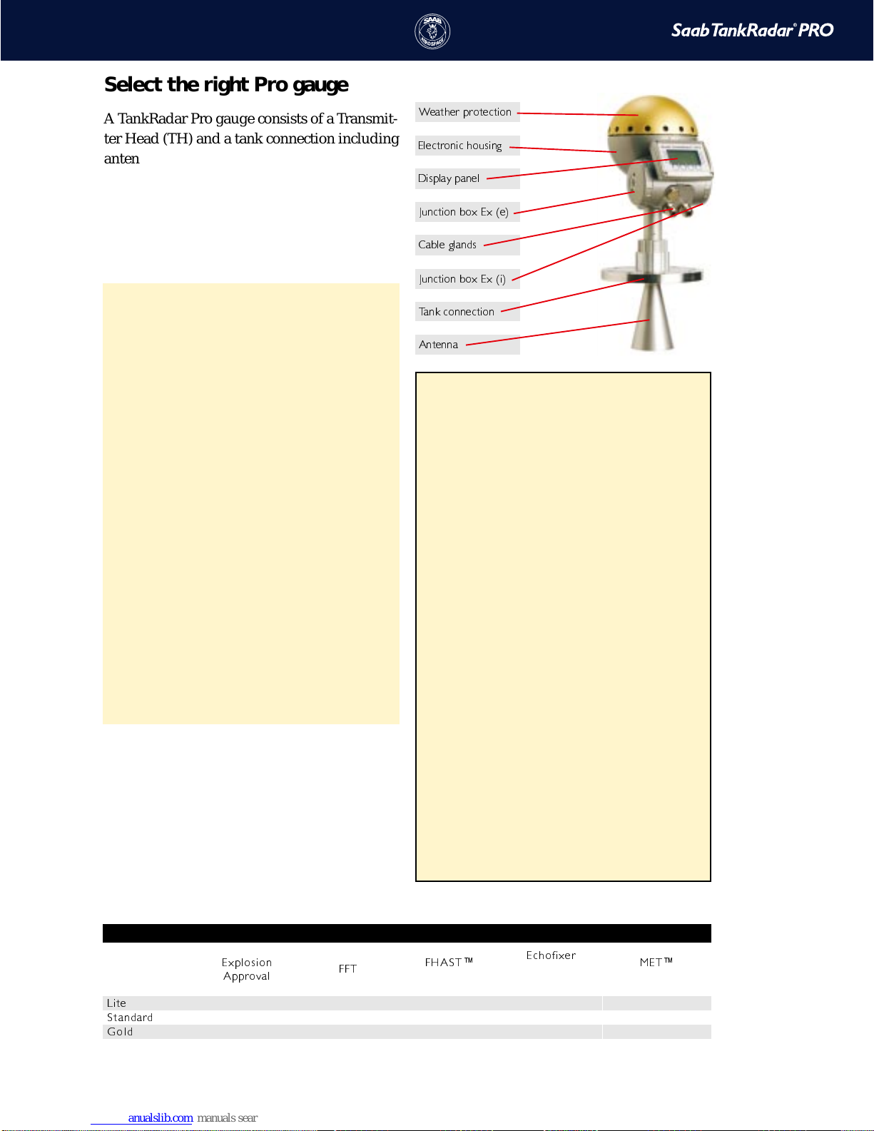
;IEXLIVTVSXIGXMSR
)PIGXVSRMGLSYWMRK
(MWTPE]TERIP
.YRGXMSRFS\)\I
'EFPIKPERHW
.YRGXMSRFS\)\M
8EROGSRRIGXMSR
%RXIRRE
Select the right Pro gauge
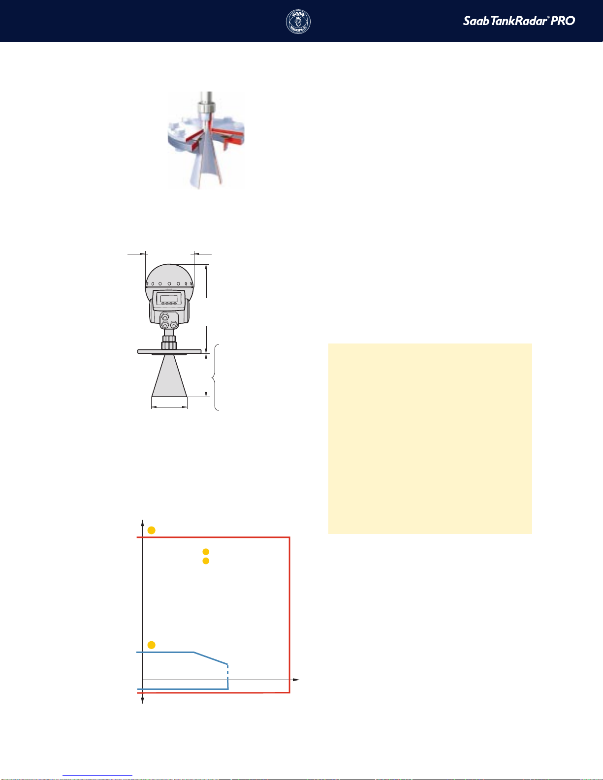
A TankRadar Pro gauge consists of a Transmit-
ter Head (TH) and a tank connection including
antenna. The TH, as well as the electronics in-
side, is interchangeable without opening the
tank.
The Transmitter Head is available in three
basic versions:
§Lite
Intended for applications in non-hazardous
areas only.Suitable for tanks without
internal structures and agitators,e.g.certain
storage tanks,water,dam applications etc.
The Lite version has only FFT calculations
enabled providing an instrument accuracy
of ±10 mm (±0.4").Echofixer,FHAST and
MET are available as options.
§Standard
For hazardous applications,suitable for
most tanks,also with internal structures,
spherical and bullet tanks.The Standard
version includes the Echofixer software
which more accurately than standard FFT
maps all microwave interference sources.
Standard instrument accuracy is ±10 mm
(±0.4") which can be improved to ±5 mm
(±0.2") using the optional software
modules.
§Gold
Gold is the most advanced version for
difficult applications in tanks with agitators,
heating coils and other disturbances. It
includes the Echofixer software,FHAST™
software for increased accuracy plus
MET™ software for further increased
disturbance echo handling. Instrument
accuracy is ±5 mm (±0.2").
Volume calculation for symmetrical tanks is
included in all versions. Strapping table for
non-symmetrical tanks is available as an op-
tion.
Various options make it possible to optimize the
gauge for different applications:
§Fast FourierTransformation (FFT)
Fast FourierTransformation is a signal
processing technique used to map the
echo structure of the tank.
§Echofixer
A software module that makes it
possible to measure on the surface in
spite of strong disturbance echoes from
mechanical structures such as agitators
and baffles.
§Fast HighAccuracy Signal
Technology (FHAST™)
A module that improves the efficiency of
the signal processing by limiting the
region to be analyzed around the surface.
This results in an improved accuracy of
±5 mm (±0.2").
§Multiple EchoTracking (MET™)
Improves the resolution and accuracy in
echo disturbed regions and close to the
tank bottom.Continuous measurement
on multiple disturbing echoes facilitates
identification of the actual surface echo.
All software options are possible to upgrade in
the field without any changes in electronics.
Upgrades are made by entering a new start
code in the gauge and can be done on a
temporary basis for trial purposes.
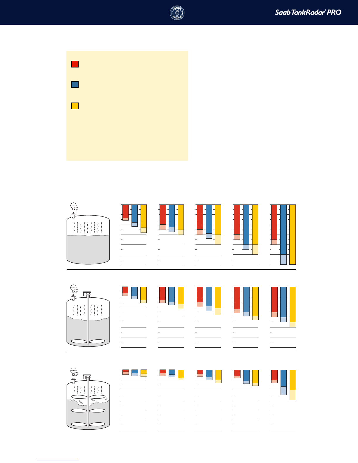
Software modules
Software modules in available Pro versions
)\TPSWMSR
%TTVSZEP **8 *,%78¬
Increased Accuracy
)GLSJM\IV
Disturbance echo
handling
1)8¬
Improved resolution
0MXI
xOption Option Option
7XERHEVH
xxOptionxOption
+SPH
x x x x x