SACER E-ACTUATOR SA1478 User manual

E-ACTUATOR CALIBRATING TOOL
Manual
Version 2.0

2
Content
1. Application of E-ACTUATOR CALIBRATING TOOL ..... 3
2. BOM List ..............................................................4
3. Software Installation Instruction .............................5
4. E-ACTUATOR CALIBRATING TOOL Connection ......... 6
5. Functions of E-ACTUATOR CALIBRATING TOOL ........ 7
6. Software Optional Interface....................................8
7. Operational Instruction of the Software ...................9
8. Common Troubleshooting.................................... 12

3
1. Application of E-ACTUATOR CALIBRATING TOOL
E-ACTUATOR CALIBRATING TOOL can be used to read and program
range of movement of electronic turbo actuators.
The E-ACTUATOR CALIBRATING TOOL enables the following actions:
1) Programming range of movement of turbo actuator.
2) Read the actuation’s angle value
3) Real-time simulation test
Notice:
A. The SA1478 calibrating tool is applied to Sacer SA1140-S
E-Actuator only; it may not available for other brands’ actuators.
B. The software will be continuously update and will be compatible
for more Sacer E-Actuators in the future.

4
2. BOM List
Name
Quantity
Photo
E-ACTUATOR CALIBRATING
TOOL
1
12V Power Adapter
Huntkey HKA04812040-7D
1
12V Power Cable
(Selections: EU/US/UK)
1
Turbo Actuator Connecting
Cable
1
USB Cable
1
E-ACTUATOR CALIBRATING
TOOL Manual
1

5
3. Software Installation Instructions
Note:
This software is applicable to Windows system 7/8/10
1) TACsetup.exe
Double click on the installation file called TACsetup.exe
2) C:\Program Files\TACalibrator
Select the installation address, default address: C:\Program Files\TACalibrator
3) Complete the installation (When the installation finished, TAC will be shown
on the desk)

6
4. E-ACTUATOR CALIBRATING TOOL Connection
Correct device setup is shown in Figure.
Connect the device to DC power supply S by using power cable
PC. Turbo actuators are connected with the TC cable.

7
5. Functions of E-ACTUATOR CALIBRATING TOOL
5.1 Reading actuator
After successful reading of the parameters the following options
are available:
5.2 Parameters
This will display actuator parameters on PC:
Figure above explains operating range of geometry lever.
Maximum angle that can be achieved by moving lever is 120°.
Actual operating range for specific actuator can be different.
A defines offset between 0°position and programmed open angle.
B defines offset between 0°position and programmed close angle.
C defines lever work angle.

8
6. Software Optional Interface
1. On/Off button: Click “On” button, the green light will be on, which
indicates the E-ACTUATOR CALIBRATING TOOL works normally
2. Color green shows the normal status of PWM signal
3. Double click the pattern which has been set
4. Setting the close angle of the actuator
5. Setting the open angle of the actuator
6. Performing the angle programming
7. Check whether the programming finish or not.
8. PWM controls actuator’s movement

9
7. Operating Instruction of the Software
Step1:Please confirm if the hardware has been connected and
powered on successfully, and then assemble the actuator to the turbo
assembly, so that you can debug your actuator through the software
Step 2: When all connections are ready, open the software.
Step 3: Open or close the device by click on the On/Off bottom
Step 4:Check the status of PWM signal;

10
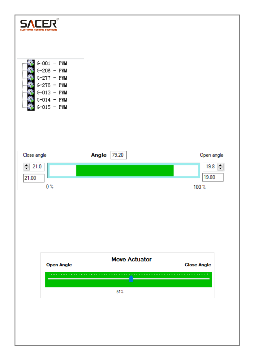
Step 5: Select the corresponding G-number, and then double click to
read the data
Step 6:The software will read the close angle and open angle of the
actuator automatically. The current open and close angles will be
shown on the PC in percentage
Step 7:You can check the if it is the maximum and minimum flow by
changing the slider in the “Move Actuator” box
If yes, you do not need to change any parameter, because it is the best
one already.
If no, you need to adjust the value. See step 8. Adjustment of Angle
Value.
Step 8:Adjustment of Angle Value
1) If move the progress bar to the far right of the “Close angle”, the
flow of the turbo assembly is bigger than expect, then need to
decrease its value. The specified value should be determined by

11
the actual working conditions; on opposing situation, the value
should be increased.
2) If move the progress bar to the far left of the “Open angle”, the
flow of the turbo assembly is smaller than expect, then the value
needs to be increased .The specified value should be determined
by the actual working conditions; On opposing situation, the value
should be decreased
3) After adjusting the angle value, please press the “Program New
Angles” button, your changes will be programmed in the actuators.
Programming success or not will be shown on the left bottom. Log File
will record the data of each programming. You can program the
actuator for multiple times until you get your ideal value.

12
8. Common Troubleshooting
Frequently Asked
Question
Solution
Device not found!
1)Check if the USB cable is loose and causes bad
connection
2)Check if the PC has read the device’s
information successfully
3)Check if the power cable is loose and causes
bad connection
Connection Started!
PWM signal fault!
1) Check if the Turbo Actuator cable is loose and
causes poor connection
2) Check if the Check if the USB cable is loose
and cause poor connection
3) Check if the PC has read the device’s
information successfully
Double click to select
the PWM signal, move
the PWM bar and find
the actuator has no
response
1) Check if the Turbo Actuator cable is loose
and causes poor connection
2) Check if you choose the correct Product
Number. You can try 8 types of Product Number
listed on the user interface.
How to restore the
original angle value?
Note: the original value
cannot be recovered if it
is mistakenly set.
Please select the corresponding G-number of
the product, right-click the selection “Open”,
then the product’s original angle value will
popup
Table of contents