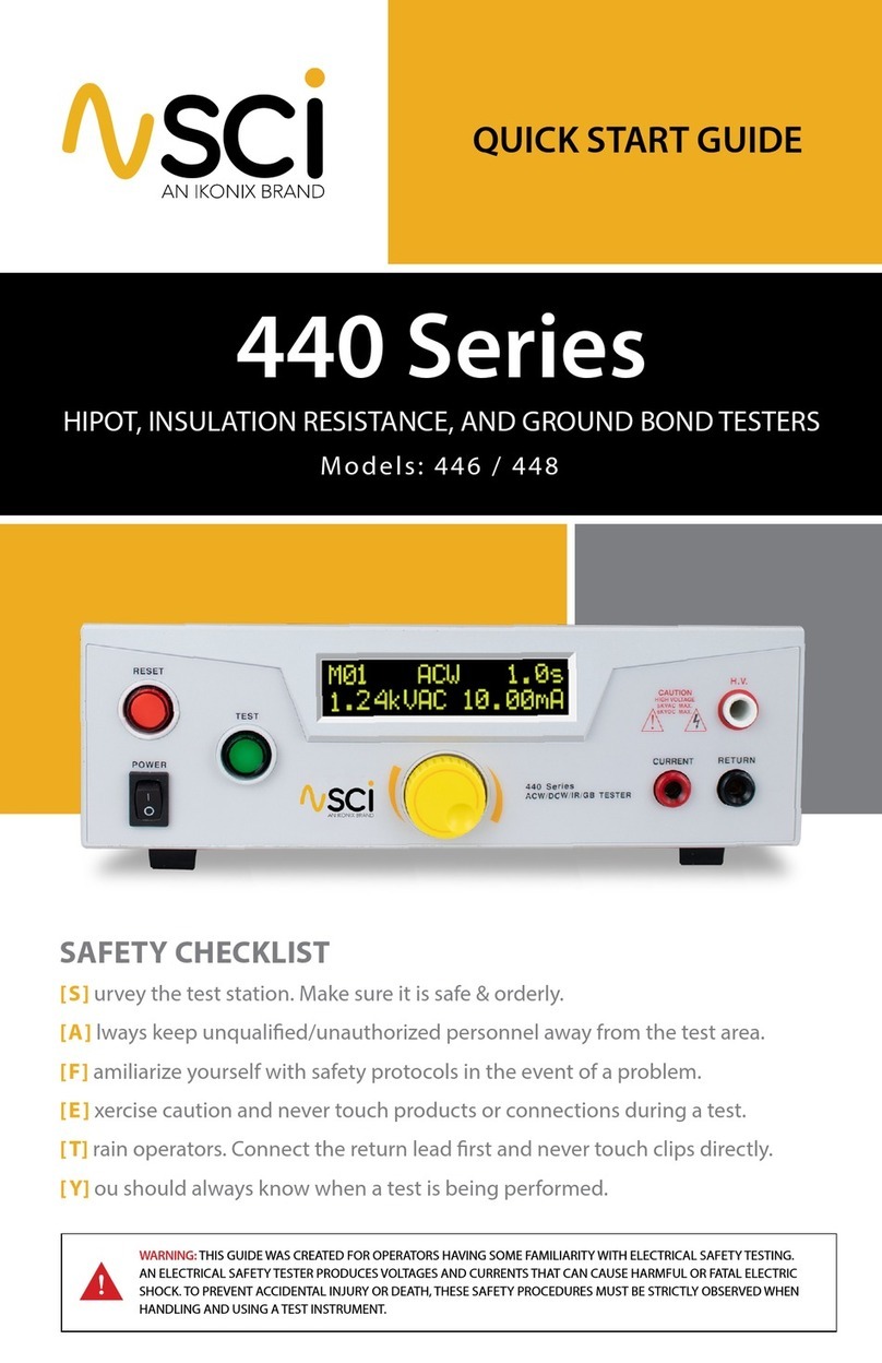
SCI 4000 Series User manual

HIPOT.COM
4000 Series
4-in-1 MULTI-FUNCTION TESTERS
QUICK START GUIDE
Models: 4320, 4520
SAFETY CHECKLIST
Survey the test station. Make sure it is safe & orderly.
Always keep unqualied/unauthorized personnel away from the test area.
Familiarize yourself with safety protocols in the event of a problem.
Exercise caution and never touch products or connections during a test.
Train operators. Connect the return lead rst and never touch clips directly.
You should always know when a test is being performed.
WARNING: THIS GUIDE WAS CREATED FOR OPERATORS HAVING SOME FAMILIARITY WITH
ELECTRICAL SAFETY TESTING. AN ELECTRICAL SAFETY TESTER PRODUCES VOLTAGES AND
CURRENTS THAT CAN CAUSE HARMFUL OR FATAL ELECTRIC SHOCK. TO PREVENT ACCIDENTAL
INJURY OR DEATH, THESE SAFETY PROCEDURES MUST BE STRICTLY OBSERVED WHEN HANDLING
AND USING A TEST INSTRUMENT.

SAFETY MADE SIMPLE®
2
1. Adjust the line voltage select switch on the rear panel of the instrument to the appropriate
input voltage rating, either 115 VAC or 230 VAC. (Model 4320 only).
Tester Setup
4320
WARNING: LOCATE A SUITABLE TESTING AREA WITH A THREE-PRONG, GROUNDED OUTLET. BE SURE THAT
YOUR THREE-PRONG OUTLET HAS BEEN TESTED FOR PROPER WIRING. READ THE SAFETY CHECKLIST OF
THIS GUIDE BEFORE STARTING TO TEST.
2. Connect the female end of the supplied NEMA style line power cord into the input power
receptacle on the rear panel of the tester. Plug the male end of the cord into a grounded
power source.
4320
3. Connect the Interlock Disable key to the Remote Input connector on the rear panel of the
instrument. This is required in order to run a test.
4320 4520
4520
4. Turn the power switch ON. Upon power up, you will see the SCI company name, model
number, and the current software version briey appear on the display. After this, you will
see the default test parameters.
4520

3
HIPOT.COM
Congure the instrument system parameters to your preferences. The instrument system
parameters are global and will affect all tests that are performed regardless of memory location
and memory step.
Default System Parameters
PLC Remote Single Step Fail Stop
OFF OFF ON
If you wish to have multiple test setups, you will need to begin by choosing a Memory
Location for each test. The 4000 Series has 6 memory locations available, each of
which contains 6 steps.
Selecting a Memory Location
START
SELECTING A MEMORY LOCATION
SET EXIT
SET EXIT SET EXIT
Edit System Parameters
1. Press the EXIT key to access
the System Parameters.
START
SET SYSTEM PARAMETERS
SET EXIT
SET EXIT
SET EXIT
Press the EXIT key to save the setting and
return to the Perform Test screen.
SET EXIT
2. Press the SET key to toggle
through parameters.
START
SET SYSTEM PARAMETERS
SET EXIT
SET EXIT
SET EXIT
Press the EXIT key to save the setting and
return to the Perform Test screen.
SET EXIT
3. Use the up & down arrow
keys to edit each
parameter
START
SET SYSTEM PARAMETERS
SET EXIT SET EXIT
SET EXIT
Press the EXIT key to save the setting and
return to the Perform Test screen.
SET EXIT
4. Press the EXIT key to save the
setting and return to the
Perform Test screen.
START
SET SYSTEM PARAMETERS
SET EXIT
SET EXIT
SET EXIT
Press the EXIT key to save the setting and
return to the Perform Test screen.
SET EXIT
START
SELECTING A MEMORY LOCATION
SET EXIT SET
EXIT
SET EXIT
Lock Memory Lock
OFF ON
1. Press the SET key from the
Perform Test screen to select
a memory location. Use the
up or down arrow keys to
select memories 1-6.
2. Press the SET key again to
select the step. Use the up
or down arrow keys to cycle
through steps 1-6.
3. Press the EXIT key to store
changes and return to the
Perform Test screen.
START
SELECTING A MEMORY LOCATION
SET EXIT SET EXIT
SET EXIT

SAFETY MADE SIMPLE®
4
Edit Test Parameters
Default Test Type Parameters
AC Hipot Mode DC Hipot Insulation Resistance Ground Bond Test
Voltage: 1.24 kV Voltage: 1.50 kV Voltage: 500 V Current: 30 Amps
HI-Limit: 10.00 mA HI-Limit: 5.00 mA HI-Limit: 0 MΩ HI-Limit: 150 mΩ
Lo-Limit: 0.00 mA Lo-Limit: 0.00 mA Lo-Limit: 1 MΩ Lo-Limit: 0 mΩ
Ramp: 0.1 s Ramp: 0.1 s Delay: 1.0 s Dwell: 1.0 s
Dwell: 1.0 s Dwell: 1.0 s Connect: O Oset: 0 mΩ
Frequency: 60 Hz Connect: O Frequency: 60 Hz
Connect: O Connect: O
EDITING TEST PARAMETERS
SET EXIT SET EXIT
SET EXIT
SET EXIT SET EXIT
1. Press the SET key from
the Perform Test screen
to conrm the memory
location.
EDITING TEST PARAMETERS
SET EXIT
SET EXIT SET EXIT
SET EXIT SET EXIT
2. Press the SET key again to
conrm the memory step
number. You should start by
modifying step 1.
3. Press the SET key a third
time until the test types
appear.
4. Use the up and down arrow
keys to toggle the test types.
ACW, DCW, IR or GND.
EDITING TEST PARAMETERS
SET EXIT
SET EXIT
SET EXIT
SET EXIT SET EXIT
EDITING TEST PARAMETERS
SET EXIT SET EXIT SET EXIT
SET EXIT
SET EXIT
5. Press the EXIT key to save
the setting and return to the
Perform Test screen.
EDITING TEST PARAMETERS
SET EXIT SET EXIT SET EXIT
SET EXIT
SET EXIT

5
HIPOT.COM
3. Press the SET key a third
time until the test types
appear.
CAUTION
5KVAC MAX.
6KVDC MAX.
H.V.
ACW / DCW / IR / GB TESTER
4320
SET EXIT
RETURN
POWER
POWER POWER CURRENT
CAUTION
HIGH VOLTAGE
5KVACMAX.
6KVDC MAX.
NL
Adapter Box Connections
To increase operator safety, you may elect to use an adapter box for products terminating in either
a two-prong or three-prong line cord. If using an adapter box, follow these instructions to safely
connect a DUT.
Hook the black lead from the adapter box (P/N 99-10005-01) into the CURRENT terminal
located on the front panel.
Plug the white lead from the adapter box into the H.V. output terminal located on the
front panel.
Hook the black ground return lead (P/N 99-10238-01) into the front panel RETURN
terminal. Connect the other end of the lead to the dead metal on the chassis of the DUT.
check to ensure a solid connection is made between the DUT and the return clip.
Plug the line cord of the DUT into the adapter box receptacle.
Conducting a Test
WARNING: DO NOT TOUCH THE DEVICE UNDER TEST ONCE YOU START THE TEST.
2
4
1
3
1
2
3
4

SAFETY MADE SIMPLE®
6
CAUTION
5KVAC MAX.
6KVDC MAX.
H.V.
ACW / DCW / IR / GB TESTER
4320
SET EXIT
RETURN
POWER
POWER POWER CURRENT
FOIL
CAUTION
5KVAC MAX.
6KVDC MAX.
H.V.
ACW / DCW / IR / GB TESTER
4320
SET EXIT
RETURN
POWER
POWER POWER CURRENT
DUT Connection
If you elect to use test leads, follow these instructions to safely connect a DUT.
Hook the black return lead (P/N 99-10238-01) into the RETURN terminal located
on the front panel. Connect the other end of the return lead to the dead metal
on the chassis of the DUT.
Hook the high current lead (P/N 99-10239-01) into the front panel CURRENT
output terminal. You may need to unscrew the terminal slightly to make the
connection. Connect the other end to the ground pin of the DUT line cord.
Plug the high voltage lead (102-055-913) into the H.V. terminal located on
the front panel. Connect the clip end of the high voltage lead to the current
carrying conductors of the DUT’s circuitry.
Exposed Metal Chassis Setup
If your chassis does not have any exposed metal, you can wrap the enclosure of the
DUT in foil and then connect the return lead to the foil.
Non Exposed Metal Chassis Setup
1
2
3
1
2
3
3
1
2
Conducting a Test
WARNING: DO NOT TOUCH THE DEVICE UNDER TEST ONCE YOU START THE TEST.

7
HIPOT.COM
PASS:
FAIL:
If the DUT passes the test, you will hear a short audible beep and the display
will indicate the test results.
If a failure occurs, you will hear a long audible alarm and the red ashing
indicator will light up. To stop the alarm press the red RESET button.
If a failure occurs, a failure code will appear on the screen. Consult your product manual to
determine the meaning of your failure code.
Pass/Fail Indication Screen
View test results by pressing the up and down arrow keys from the Perform Test screen.
1. Connect the Interlock Disable Key (P/N 99-10040-01) to the Signal Input connector on the rear
panel of the tester. If you’re not utilizing a DUT enclosure (P/N 99-10715-01) or other safety
device, the Interlock Disable Key is required in order to run a test.
2. Push the green TEST button on the front panel. The DUT is tested for a duration equal to the
Ramp and Dwell settings.
Conduct A Test
WARNING: DO NOT TOUCH THE DEVICE UNDER TEST ONCE YOU START THE TEST.
4320 4520
4520
Selecting a Memory Location

SAFETY MADE SIMPLE®
8
28105 N. Keith Drive, Lake Forest, IL 60045 USA
© 2019 SCI
V1.1 1/19
Testers For Electrical Safety Compliance
This manual suits for next models
2
Table of contents
Other SCI Test Equipment manuals