Saci AR4DCT User manual

1
AR4DCT
DIN-rail Multi-function DC Power Meter
User Manual

2
Content
1. SAFETY INSTRUCTIONS.........................................................................................................................................1
2. PRODUCT DESCRIPTION........................................................................................................................................1
2.1 OVERVIEW................................................................................................................................................................1
2.2 FUNCTION.................................................................................................................................................................1
MAIN MODULE (AR4DCT)...........................................................................................................................................1
2.3 TECHNICAL PARAMETER..........................................................................................................................................2
2.4 ENERGY METERING..................................................................................................................................................3
2.5 MAX./MIN.VALUE AND DEMAND...............................................................................................................................3
2.6 DIGITAL INPUT..........................................................................................................................................................3
2.7 RELAY OUTPUT.........................................................................................................................................................3
2.8 COMMUNICATION .....................................................................................................................................................4
3. INSTALLATION AND WIRING..................................................................................................................................4
3.1 DIMENSION...............................................................................................................................................................4
3.2 INSTALLATION ..........................................................................................................................................................4
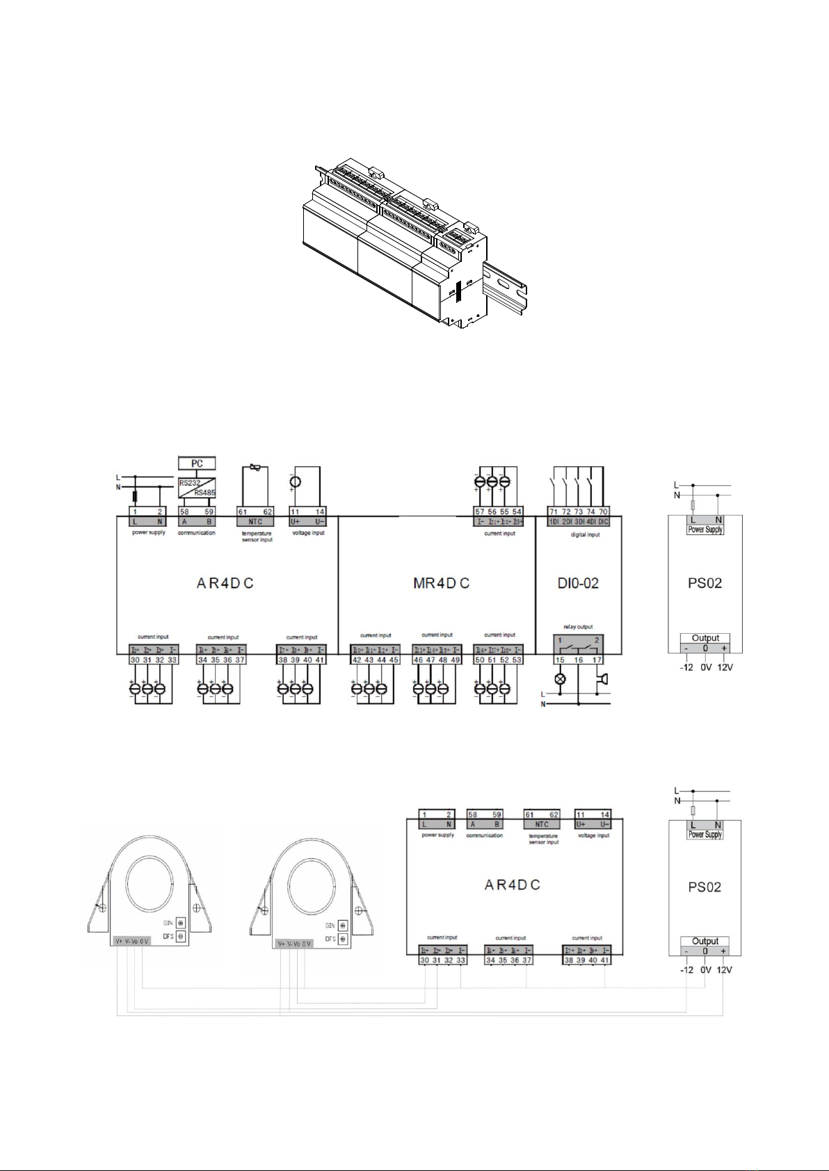
3.3 WIRING.....................................................................................................................................................................5
TYPICALWIRING..............................................................................................................................................................5
3.3.1AR4DCT +MR4DCT +DIO-02.........................................................................................................................5
4. OPERATION ................................................................................................................................................................8
4.1 PANEL DESCRIPTION................................................................................................................................................8
4.2 INSTRUCTION FOR OPERATION KEYS.......................................................................................................................8
4.3 INSTRUCTION FOR MEASUREMENT INTERFACE .......................................................................................................8
5. SETTING ......................................................................................................................................................................9
5.1 PROGRAMMING MODE..............................................................................................................................................9
6. COMMON PROBLEMS AND TROUBLESHOOTING.........................................................................................14
ABOUT COMMUNICATION ..............................................................................................................................................14
INCORRECT MEASUREMENTS.......................................................................................................................................14
ABOUT INCORRECT POWER RUNNING..........................................................................................................................15
THE METER DOES NOT RESPOND TOANY OPERATION .................................................................................................15
OTHER ABNORMAL PHENOMENA ..................................................................................................................................15

1
1. Safety instructions
Thank you for choosing the meter researched and developed by our company. In order to make it convenient for you
to purchase and use the meter safely, correctly and efficiently, please read this manual carefully before using the product,
and pay attention to several points as follows.
CAUTION:
◆Make sure only the qualified technicians perform the installation and maintenance;
◆Before performing wiring operation to the meter, make sure the input signal and the power supply are switched off;
◆The proper voltage detecting device should be used to guarantee no voltage in any part of the meter;
◆The electrical parameters supplied should be within the rated range;
The following situations may result in damages to the meter or cause mistakes in the operation of the meter.
◆The voltage of the auxiliary power supply goes beyond the rated range.
◆The frequency of the power distribution system goes beyond the rated range.
◆The input polarity of the voltage or the current is incorrect.
◆Remove or connect the communication plugs without powering off.
◆Connect the terminal wires against the related instructions.
Please don’t touch the terminals when the meter is in operation!
2. Product description
2.1 Overview
AR4DCT are used to manage multi-circuit DC power supply such as photovoltaic combiner box. They can measure
basic electrical variables such as voltage, current, power and energy of up to 33 DC circuits. AR4DCT can realize current
measurement of 33 circuits at most, 4 digital inputs and 2 relay outputs. They also have over current alarm, over voltage
alarm, under voltage alarm and DI linkage alarm functions. In addition, AR4DCT has one temperature measurement
function. Communication interface on the meter makes it simple to connect it to smart distribution system and energy
management system to share monitoring data and energy quality data.
2.2 Function
Main module (AR4DCT / AR4DC)
Function
Instruction
Channel
Current measurement
External Hall sensor input
9
Voltage measurement
Direct input
1
Energy metering
Bi-directional energy
■
Alarm protection
DI linkage alarm protection
■
Temperature alarm protection
■
Over current alarm protection
■
Over voltage alarm protection
■
Under voltage alarm protection
■
Standard communication
RS485(Modbus-RTU)
■

2
Display mode
Segment LCD
Installation method
DIN-rail installation
Extendsion module
Code of input and
output module
Instruction
MR4DCT
12 channels of current measurement
Up to 2 MR4DC can be connected.
DIO-02
4 digital inputs/2 relay outputs
2.3 Technical parameter
Item
Parameter
Accuracy
Electrical variables
0.2%
Energy
1.0S
Signal
input
Temperature 注
2% ,NTC thermistor ,-10 ~110℃, (Only
available in AR4DCT)
Voltage
Range
Direct input
AR4DCT:0-1500V
Consumption
<0.6VA
Impedance
>6MΩ
Current
Range
External Hall sensor input,-4~4V
Consumption
<0.01VA(each circuit)
Impedance
>200kΩ
Power
supply
Working range
AC/DC(80~270)V
Frequency
50/60 Hz
Consumption
≤5VA
Output
Energy pulse
Photoelectric isolation output, pulse width
80ms±20%, frequency <10Hz
Relay output
Capacity AC250V 5A or DC30V 5A
Isolation voltage between contact and coil
2500VAC rms
Input
Digital input
Passive dry optocoupler isolation input, isolation
voltage 2000VAC rms
Communi
cation
module
RS485 port
Modbus-RTU protocol, communication speed
2400~38400bps, no check, odd check and
even check optional
Mechanic
al feature
Weight
About 300g
Dimension
AR4DCT main module 72x90x63.5mm
MR4DC module 72x90x63.5mm
DIO-02 module 36x90x63.5mm
IP protection
Front case IP50

3
Rear case IP20
Environm
ent
condition
Working environment
-25~70℃
Storage environment
-40~85℃
Rated humidity
5~93%(no condensation at 50℃)
Pollution degree
2
Measurement type
III
Insulation
Between signal, power supply, output terminal
and case resistance > 100MΩ
Power supply and input > AC 3kV
Power supply and output > AC 3kV
Input and output> AC 2kV
EMC
III
2.4 Energy metering
Detailed energy metering function is as follows,
- Total bi-directional energy
- Bi-directional energy of each circuit
Min. resolution is 0.01kWh. Energy display range is 99999999000 kWh (99.9 billion kWh). User can clear energy data
by manual according to practical requirements after inputting correct password.
2.5 Max./min. value and demand
Meter can record max./min. value of voltage, current and power, and save these data of present month, last month
and the month before last month. Please refer to communication list for detailed recording parameters.
Meter can measure the demand of current and power in each circuit. Max./min. value and demand only can be read
through communication, but not can be shown on the panel of meter.
2.6 Digital input
This meter supports 4 digital inputs. The digital input uses the method of dry contact input. DC 15V operation power
supply is provided inside the meter without the need for external power supply. It can be used to monitor closing/opening
status, handcart position, operation status of capacitance compensation cabinet, etc. The status information can be
transmitted remotely to monitoring system through communication interface so as to realize automatic opening and
closing with the remote/alarm relay function.
2.7 Relay output
The meter supports two relay outputs.
The relay output has four different work modes: off, remote control and off-limit alarm.
Off: relay output function is off, and the status relay returns to defaulted status.
Remote control: to receive PC and PLC command, and to control the closing and opening of relay.
Off-limit alarm: set corresponding relay as “Off-limit alarm” mode, set alarm electrical variable in “Mode” item, set
alarm delay time in “Delay” item, set alarm limit percentage of electrical variable in “Value” item, set hysteresis value
percentage in “Recover” item.

4
2.8 Communication
Meter has one RS485 communication interface adopting standard Modbus-RTU protocol. RS485 interface should be
connected with STP. One piece of bus can be connected with 32 meters at most. The start and end terminals of bus can
be connected with terminal resistance.
3. Installation and wiring
3.1 Dimension
3.1.1 AR4DCT main module dimension
72
90
63.5
35.5
3.1.2 MR4DCT module dimension
72
90
63.5
35.5
3.1.3 DIO-02 module dimension
36
90
63.5
35.5
3.2 Installation
Fixed on 35mm standard rail

5
3.3 Wiring
Typical wiring
3.3.1 AR4DCT + MR4DCT + DIO-02
Other typical wiring

6
Note:
1. Auxiliary power supply:AC/DC (80~270)V
2. Rated current of fuse:0.5A
3. AR4DCT :Voltage input: input voltage should not be higher than 1500V;
4. Current input: input current should be connected via Hall sensor;
5. Please make sure the directions of voltage an current are same;
6. Wiring mode setting inside the meter must be the same as external wiring method.

7
Instruction for No. of wiring terminals are as follows,
Power supply
1,2
AC/DC
Current signal
30-57
Current input
Voltage signal
11,14
Voltage input
Energy pulse
output
47,48
Active energy pulse output
RS485
communication
58,59
Corresponding to A and B
Relay output
15—17
2 relay outputs, 16 is common end
Digital input
70—74
4 digital inputs, 70 is common end
Temperature
sensor input
61 ,62
Only available in MR4DCT

8
4. Operation
4.1 Panel description
Display
screen
Indication
light
Keys
Front panel includes three parts which are data display screen, LED power supply indication light and operation
keys.
4.2 Instruction for operation keys
Keys
Measurement interface
Programming interface
自检
Switch main interfaces
Select a bit or modify an item
消音
Check more information at
present interface in cycle
Modify data at the selected bit or
select an item
Menu
翻页
Keep pressing it for 3
seconds to enter
programming mode
Cancel or return to upper level menu
通道
Confirm or enter next level menu
4.3 Instruction for measurement interface
Measurement interface
Instruction
Voltage value
U = 201V
Show current value of first circuit: I-01 = 258A,
Press
消音
to check current value of other circuits (21
circuits at most).
Show total power P = 99.00MW
Press
消音
to check power value of other circuits (21
circuits at most).
Press
消音
to check export energy and import/export
energy of other circuits (21 circuits at most).
Show the status of digital input
Show the status of relay

9
Show temperature value
T =25.8 ºC
Show time
2011-07-07
12:53:01
Overview of display interface
Note: Temperature display interface is not available in AR4DC.
5. Setting
User can check and set parameters
5.1 Programming mode
Enter the programming mode
On the measurement display interface, keep pressing “ ” for more than 3s, “ ” will be displayed on the meter,
and then click “ ” or “ ” key to select “ ”; press “ ” key to enter the password input interface; input the password
(defaulted password is 0001) through “ ” or “ ” key, and press “ ” key to enter the setting interface if the password is
correct.
Exit programming mode
When the data (or items) in the third-level menu is changed, press “ ” key to confirm changes and press “ ” key
to exit the interface. Press “ ” key to return to the first-level menu, and then press the “ ” key, the “ -- ” will be
displayed on the meter. At this time, there are three operations optional:
1) Save the setting parameters: press “ ” key;
2) Not save the setting parameters: press “ ” or “ ” key to select “ -- ” and then press “ ” key;
3) Return to the programming menu: press “ ” key;

10
Setting operation: “ ” key is used to shift the menu and move the numerical value to left; “ ” key is used to shift the
menu, increase or decrease the numerical value or move the decimal point; “ ” key is used to return; “ ” key is used
to confirm the entering menu and modified value.
Detailed instruction of setting menu is as follows,
First level
Second level
Third level
Code
Instruction
Code
Instruction
Code/Number
Instruction
System
setting
User password
~
User password
Cycle display in
measurement
interface
No cycle display
~
Cycle display interval, unit: s
Back-light duration
time
~
0: normal on, unit: s
Energy pulse output
Off
Import energy
Export energy
Energy pulse
constant
~
Unit imp/kWh
Clear demand
Not clear demand
Clear demand
Clear energy
Not clear energy
Clear energy
Input
setting
Rated voltage
~
Unit V (fixed value)
Current range
-4~4V(fixed value)
Rated current
~
Unit A (all current circuits)
…
Rated current of
#1~21 circuits
~
Unit A
Off-limit flashing
alarm
~
Unit 0.1%(voltage, current
signal)
small signal cutting
percentage
~
Unit 0.1%(voltage, current,
power)
Demand
setting
Item
Current, active power
Calculation method
Slip
Fixed zone
Time of calculation
point
~
Unit s
Time of slip or fixed
zone
~
Period 1~30
Communic
ation
setting
Meter address
~
1~247
Baud rate
~
1200~38400bps
Data format
No check, one stop bit
No check, two stop bits
Odd check, one stop bit
Even check, one stop bit
Communication
protocol
Modbus-RTU
Relay
Working mode
Alarm mode

11
output
setting
Remote mode
Off
Pulse width
~
Unit 0.1s
Alarm item
,
Over voltage/under voltage
alarm
、
Over current/under current
alarm
High temperature alarm
~
DI closed alarm
~
DI open alarm
Alarm value
percentage
~
Unit 0.1%(temperature range
100.0℃)
Hysteresis value
percentage
~
Unit 0.1%( temperature range
100.0℃)
Action delay
~
Unit 0.1s
Time
setting
Year, month, day,
hour, minute, second
User
informatio
n
Main module
Software version
Current module
I/O module
Overview of user menu
Operation
key
Off-limit
flashing
alarm
% of rated
value
Small signal
cutting
% of rated value
Meter
address Baud rate Data format
Relay output
working mode Energy pulse
width
Voltage range Rated current
of #1 circuit
Alarm mode Alarm delay
time
Alarm hysteresis
value
Alarm value
Cycle display
interval LCD backlight
duration Energy pulse
constant
Programming
password
Menu
>3s
System parameter
setting
Signal input
setting
Communication
setting
Relay output
setting
Energy pulse
setting
System time
setting Time setting
User
information Software version
of meter Software version
of I/O module
Software version
of current module
Clear demand
Calculation
time Calculation
time zone
Measurement
item Calculation
method
Demand setting
Current
range Rated current
of #1-21 circuits
Clear energy
Communication
protocol
Relay output
setting Relay output
working mode Energy pulse
width Alarm mode Alarm value Alarm hysteresis
value Alarm delay
time
Rated current
of #21 circuit

12
5.2 System setting
E.g. To set password to as 112, set cycle display interval as 6s, set backlight duration time as 60s, the operation
process is as follows
Enter programming interface,
select system setting menu
Change password to 112
Set cycle display interval as 6s
Set backlight duration time as 60s
Save modified data and
exit programming mode
Menu
>3s
Menu Menu
5.3 Input signal setting
User can set rated current value according to practical situation at field.
E.g. To set rated voltage value as 1000V, external Hall sensor input ratio is 100.0A/4V, the operation process is as
follows,
Enter programming interface,
select signal input setting menu
Set rated voltage as 1000V
Save modified data and
exit programming mode
Menu
Menu
> 3 s
Menu
Set current range as 4.000V
Set rated current as 100.0A

13
5.4 Alarm setting
E.g. To set No. 1 relay output as over voltage alarm, set pulse width as 10.0s, set alarm value as 120.0%, set
hysteresis value as 5.0%, set alarm delay as 1.0s, the operation process is as follows,
Enter programming interface,
select signal input setting menu
Menu
Menu
>3s
Menu
Set relay working mode as alarm mode Alr
Set relay pulse width as 10.0s
Set alarm item as over voltage alarm
Set alarm value as 120.0% of rated value
Set hysteresis value as 5.0% of rated value
Set alarm delay time as 1.0s
Save modified data
and exit programming mode

14
5.5 Communication setting
E.g. To set communication address as 2, set baud rate as 9600bps, set data format as odd check, the operation
process is as follows,
Enter programming interface,
select communication setting menu
Menu
Menu
>3s
Menu
Set meter address as 2
Set baud rate as 9600bps
Set communication data format as O.8.1 odd check
Save modified data
and exit programming mode
6. Common problems and troubleshooting
About communication
Meter does not send data back
First make sure the communication setting information of the meter such as address, baud rate and check mode
corresponds to the requirements of host computer. If several meters at field do not send data back, please check whether
the communication bus at field is connected correctly and whether RS485 converter works normally.
If there is only one meter or a few meters communicate abnormally, related communication bus is also needed to be
checked. You may check whether there is an error in the host computer by exchanging the subordinate machine
addresses of normal meter and abnormal meter. Besides you may check whether there is a fault in the meter by
exchanging the installation positions of normal and abnormal meters.
Data sent back by the meter is incorrect
Communication data which is opened to users includes primary grid “float” type data and secondary grid “int/long”
type data. Please read the instruction for data storage address and format in communication address table carefully, and
make sure to transmit data according to relative format.
It is suggested to download testing software ModScan32 for Modbus-RTU communication protocol. This software
adopts standard MODBUS-RTU protocol which can display data in the formats such as integer, float and hexadecimal, so
that you can compare the data with measured data displayed on the meter directly.
Communication indication sign information
There is a communication sign on the display screen. It will flash when receiving data in communication test process.
Incorrect measurements
Make sure that the meter has been input right voltage and current. The multimeter is used for measuring voltage and
current, and the clip-on meter is used for measuring current signal.

15
Make sure the signal wire is connected correctly, for example the dotted terminals of current signal (i.e. inlet) as well
as the phase sequence of each phase should be correct. Observe power display interface of the meter, and its power
symbol is displayed positive under normal condition and negative only when it is under power generation condition which
is caused by wrong connection of inlet-outlet lines.
About incorrect power running
Energy is accumulated on the basis of power measurement; check whether power value displayed is consistent with
actual load. As the product supports bi-directional energy measurement, energy will be accumulated to backward energy
instead of forward one if wires are not connected properly or total active power is negative. The most common problem on
spot is inlet and outlet wire of current transformer are in reverse connection. Observe signed active power in split phase,
and it may be negative because of wrong connection.
The meter does not respond to any operation
Make sure power supply is connected to the right terminals of meter. If the voltage of power supply is out of specified
range, the meter will be damaged and will not be reset. Please use multimeter to check the voltage of power supply at first.
If the voltage is normal and the meter does not show anything, please try to power it up again.
Other abnormal phenomena
Please contact our technical service department to give a detailed description of the field condition. Our technicians
will analyze possible causes according to your description. The company will appoint technicians to deal with problems on
spot as soon as possible if the problem can not be settled after oral communication.
Table of contents
Other Saci Measuring Instrument manuals