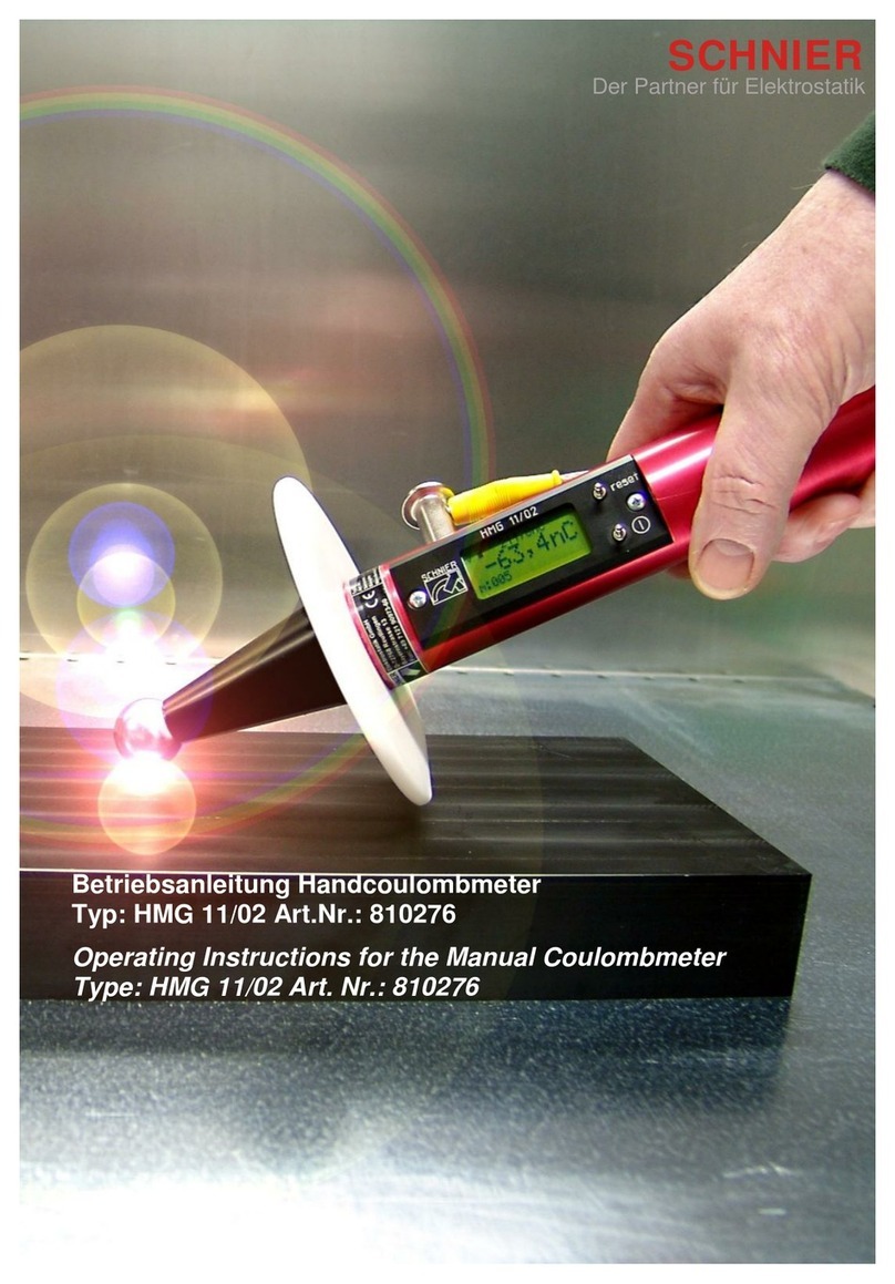
SCHNIER FLOCK Checker User manual

1
Part.No.:
810523
Operating manual
FLOCK Checker

Operating manual 810523-BAL-EN-220609 Status 06.09.2022 Seite 2 von 12
Contents
1. Product and manufacturer 3
1.1. Product description 3
1.2. Specifications 3
1.3. Product identification 3
1.4. Nameplate 3
1.5. Warranty 4
1.6. Manufacturer 4
2. Guide to these operating instructions 4
3. Intended use 4
4. Structure and overview 5
4.1 Structure of the FLOCK Checker 5
5. Functional description 6
5.1. Commissioning 6
5.2. Display 7
5.3. Performing measurements 8
5.4. Charging the FLOCK Checker 8
6. Menu and further functions 9
6.1. Switch of 9
6.2. To measuring 9
6.3. Show memory 9
6.4. Clear memory 9
6.5. Settings 10
6.6. Calibration 10
7. Error 11
8. Scope of delivery 11
9. Accessories 11
10. Declaration of Conformity 12

Operating manual 810523-BAL-EN-220609 Status 06.09.2022 Seite 3 von 12
1. Product and manufacturer
Congratulations on the purchase of your FLOCK Checker!
1.1. Product description
The FLOCK Checker is a measuring device for determining the conductivity of flock fibers.
To ensure high-quality flocking, the conductivity of the flock fibers used plays a major role.
You can measure this easily and precisely with our FLOCK Checker and thus offer con-
sistent quality of your flocked parts.
Each manufacturer of flock fibers offers different fibers with different preparations. Accord-
ingly, these also have different conductivity.
Please refer to the respective data card of your fibers for the exact dates.
1.2. Specifications
Power supply
Li-Ion battery 3,7 V / 3000 mAh
USB C Charger
85 - 264 V AC / 47 –63 Hz
Operating time
>5 h
Automatic. switch-off function
15 min
Temperature range
+15°C to 40°C max. 95% rel. humidity, non-
condensing.
Operating altitude above sea
level, maximum
1.000 m
Size (incl. Electrode)
290 x 80 x 80 mm
Weight
0,8 kg
Protection class
IP 54
1.3. Product identification
This operating manual is part of the device:
Product: Conductivity meter
Type: FLOCK Checker
Part No.: 810523
1.4. Nameplate

Operating manual 810523-BAL-EN-220609 Status 06.09.2022 Seite 4 von 12
1.5. Warranty
The warranty is 24 months after delivery.
Any kind of warranty expires if the device has been opened, modified, parts have been
replaced with non-original parts or these operating instructions have not been observed.
1.6. Manufacturer
SCHNIER Elektrostatik GmbH
Bayernstr. 13
72768 Reutlingen
Deutschland
Phone: +49 (0) 71 21 / 90 973 - 60
Fax: +49 (0) 71 21 / 90 973 - 99
www.schnier.de
www.schnier-flock.de
Headoffice: Reutlingen HBR 354 531
USt.-IdNr.: DE 146 481 986
General Manager: Olav Schnier
2. Guide to these operating instructions
These operating instructions must be read, understood and observed in all points by all
persons who are responsible for the equipment. Only with knowledge of these operating
instructions errors can be avoided and safe and trouble-free operation be ensured.
SCHNIER Elektrostatik GmbH does not accept any liability for damage resulting from non-
observance of these operating instructions!
3. Intended use
This instrument is intended exclusively for use as a conductivity meter of flock fibers.
Any commissioning outside this provision is prohibited.
Damages / modifications:
No structural modifications of any kind may be made to this device.

Operating manual 810523-BAL-EN-220609 Status 06.09.2022 Seite 5 von 12
4. Structure and overview
4.1 Structure of the FLOCK Checker
1 Electrode
2 Display
3 (I)-Button
4 Reset- / Save-Button
5 Cover charging socket
6 POAG Plug for grounding
1
2
3
4
5
6

Operating manual 810523-BAL-EN-220609 Status 06.09.2022 Seite 6 von 12
5. Functional description
5.1. Commissioning
•Take the FLOCK Checker out of the case and screw on the attachment electrode
carefully and not too tight.
•Remove the protective cap.
•Press the (I) button [3] upwards and hold for approx. 2 seconds.
•The unit starts up and performs a self-test.
•As soon as the value "0" is shown in the display [2], the FLOCK Checker is ready
for measurement.
The attachment electrode [1] must always be clean and dry. Mo-
isture and impurities falsify the measurement result.
The display for the flock measurement is in the usual standard scale divisions [Nrm].

Operating manual 810523-BAL-EN-220609 Status 06.09.2022 Seite 7 von 12
5.2. Display
1 Battery indication and time
2 Current measured value
3 Maximum measured value
4 Number of stored measured values
1
2
3
4

Operating manual 810523-BAL-EN-220609 Status 06.09.2022 Seite 8 von 12
5.3. Performing measurements
•Before measuring, please remove the protective cap from the electrode.
•Commissioning according to 5.1
•Dip the electrode of the FLOCK Checker into the flock to be measured and loosen
it slightly.
•Now press the electrode firmly onto the flock with constant pressure.
•3 seconds after the FLOCK Checker has made contact with the fibers, a measu-
rement result is recorded and shown on the display.
•The handle vibrates to indicate that the measurement is complete.
•Now pull the FLOCK Checker out of the flock and read the measurement result.
•If you want to take a new measurement, set the value in the display to "0" by pres-
sing the Reset / Save button [4] down once.
•To save the value, press the Reset / Save button [4] upwards.
This also sets the value in the display to "0".
•The value "Max" is also shown in the display. This is the maximum value that was
measured in this measurement series. This value remains until a higher value is
measured. To set it to "0" press the Reset / Save button [4] down twice.
Flock fibers that are good to process usually have a value of 60 -
120 standard parts of scale [Nrm].
5.4. Charging the FLOCK Checker
•The FLOCK Checker will be delivered with a USB-C wide range charger. Also a
USB-C to USB-A cable and adapters for UK and US.
•To charge the FLOCK Checker, please unscrew the cover for the charging socket
[5]. Underneath you will find the USB-C port.
•Plug the cable into the socket and connect it to the charger.
•Plug the charger into a power outlet.
•The following message appears in the display and no measurement can be per-
formed during charging:

Operating manual 810523-BAL-EN-220609 Status 06.09.2022 Seite 9 von 12
6. Menu and further functions
To access the menu, briefly press the (I) button [3] upwards.
By pressing the (I) button upwards, you can scroll through the menu items.
To select an entry, press the (I) button [3] downwards.
You can select from the following:
6.1. Switch off
Switches the device off.
To switch off the device, select the "switch off" entry and press the (I) button down.
6.2. To measuring
Takes you back to measuring.
To return to measuring, select the entry "to measuring" and press the
(I) button down.
6.3. Show memory
All stored measurement results with date and time are displayed here.
To access the stored measurement results, select the "show memory" entry and press the
(I) button down.
To return to the measurement, press the (I) button downwards.
To save measured values, press the reset / save button upwards after the measurement.
6.4. Clear memory
Here you can clear the stored measurement results.
To delete all measured values, select the "clear memory" entry and press the (I) button
down.
In the following screen, select the entry "yes" and press the (I) button down.
To delete only individual measured values, select the entry "show memory" and press the
(I) button downwards.
By pressing the reset/save button downwards, the top value is deleted.

Operating manual 810523-BAL-EN-220609 Status 06.09.2022 Seite 10 von 12
6.5. Settings
Here you get to the settings and can choose from the following entries:
6.5.1 Timer
Here, the measuring timer can be displayed at the lower right edge of the screen.
To do this, select the "Timer" entry and press the (I) button down.
Then select the "Yes" entry and confirm by pressing the (I) button downwards.
6.5.2 Vibration
Here, the vibration of the handle can be switched on and off to confirm a success-
ful measurement.
To do this, select the "Vibration" entry and press the (I) button down.
Then select the "Yes" entry and confirm by pressing the (I) button downwards.
The device vibrates briefly to confirm.
6.5.3 Date
Here you can set the date and time.
To do this, select the "Date" entry and press the (I) button down.
The individual digits can be set by pressing the (I) button upwards.
By pressing the (I) button downwards, the cursor always moves one position to the
right.
After all positions have been set correctly and the cursor is at the last position, you
will be asked whether you want to cancel or confirm. Please make your selection
by pressing the (I) button upwards and confirm by pressing the (I) button down-
wards.
6.6. Calibration
This entry is protected with a password and is used exclusively for calibration by
SCHNIER Elektrostatik GmbH.

Operating manual 810523-BAL-EN-220609 Status 06.09.2022 Seite 11 von 12
7. Error
This message means that the measured value is higher than 125 standard scale division
[Nrm].
Simply delete it again by pressing the (I) button downwards. You can then carry out a new
measurement.
8. Scope of delivery
•FLOCK Checker
•Attachment electrode with protective cover
•Sturdy carrying case
•USB charger incl. adapter for UK and US
•USB-C- to USB-A-Cable
9. Accessories
•Table mount (Part.No. 080421)

Operating manual 810523-BAL-EN-220609 Status 06.09.2022 Seite 12 von 12
10. Declaration of Conformity
Manufacturer: SCHNIER Elektrostatik GmbH
Bayernstrasse 13
D-72768 Reutlingen
Product: Measuring device
Type: Conductivity meter
SCHNIER Part.-No.: FLOCK Checker Part-No. 810523
Handelsbezeichnung: FLOCK Checker
Function: Measuring instrument for determining the conductivity
of flock fibers.
DIN 54345-1:1992-02 Testing of textiles; Electrostatic behavior;
Determination of electrical resistance quantities
Rommelsbach 06.09.2022
Olav Schnier (Geschäftsführer)
This manual suits for next models
1
Table of contents
Other SCHNIER Measuring Instrument manuals