Sacred Sun GFMG Series User manual


C
on
ten
t
s
Chapter I: Product Introduction
1. Product Characteristics ...............................................................................................01
2. Main Applications ........................................................................................................02
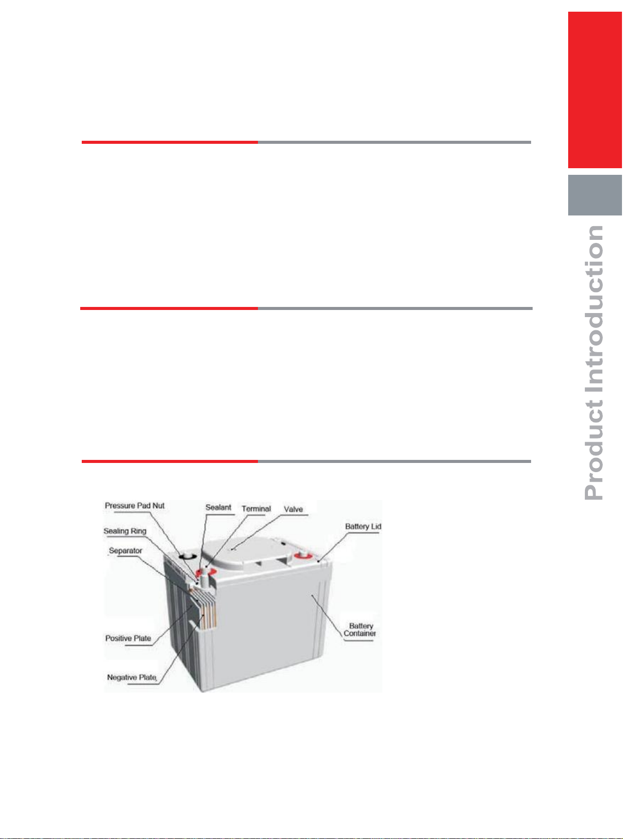
3. Battery Construction ....................................................................................................02
4. General Specification ..................................................................................................03
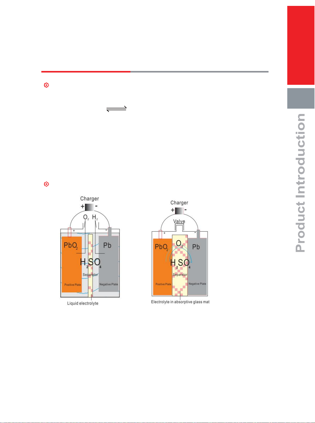
5. VRLA Technology ........................................................................................................05
Chapter II: Electrical Characteristics
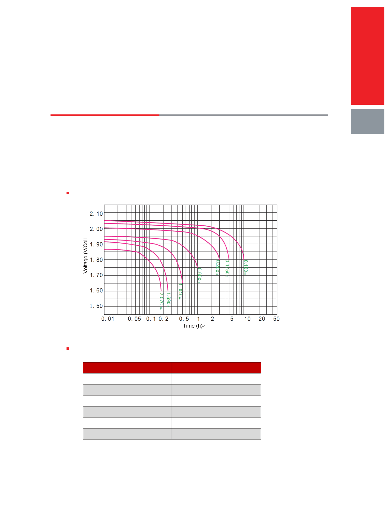
1. Discharge Characteristic Curve ...................................................................................06
2. Charge Characteristic Curve .......................................................................................07
3. Performance Data........................................................................................................08
Chapter III: Operation and Maintenance
1. Security Instruction ......................................................................................................12
2. Operation Parameters .................................................................................................13
3. Factors Influencing Capacity .........................................................................15
4. Temperature Effect On Battery Capacity .........................................................15
5. Temperature and Floating/Equalizing Charge Voltage ........................................16
6. Temperature Effect on Battery Service Life ......................................................17
7. Charge Requirement ..................................................................................17
8. Storage ....................................................................................................19
9. Maintenance .............................................................................................19

Chapter I: Product Introduction
Product Characteristics
Advantages
Design life: 12 years(25℃);
EUROBAT Classification Long life;
High discharge performance;
99%+ gas recombination efficiency;
Maximum charge efficiency;
Low self-discharge rate;
Easy installation and handling;
Design features
Positive plates
Negative plates
Separators
Container and lid
Terminal posts
Posts sealing
Vents
Electrolyte
Plates suspension
Inter-cell connectors
Terminal hardware
01
01
Thick flat pasted plate with lead-calcium-tin grid alloy ;
Flat pasted plate with lead-calcium grid alloy ;
Microporous AGM separator ;
High-strength ABS (option: available in Flame Retardant UL94 V0 version) ;
High-conductivity terminals with threaded inserts ;
Double sealing structure ;
Sacred Sun Patent, two-layer and explosion-proof acid filter valve;
Absorbded sulfuric acid;
Bottom supported ;
Insulated rigid copper ;
Stainless steel + Cover .

Main Applications
Telecommunications;
Emergency power;
UPS
Electrical Power plants and substation
Transportation
Standards
GB/T19638.2-2005
IEC60896-21/22:2004
Eurobat guide
Installation compliant with EN50272-2
Battery Construction
GFMG-560 for Example
02

General Specification
2V series
G F M G - X X X X
6V/12Vseries
X G F M G - X X X X
Rated capacity at C10
High power
Sealed
Valve regulated
Stationary
Rated capacity at C10
High power
Sealed
Valve regulated
Stationary
Cell number
03

GFMG series
Table 1-1 GFMG series general specification
Battery Type
Rated
Voltage (V)
Rated
Capacity
(Ah,25℃)
Dimensions (mm)
Weight
(kg)
Short Circuit
Current (A)
Internal
Resistance
(mΩ,25℃)
Terminal Type
Terminal
Layout
C10
1.80V/cell
Length
Width
Height
Total
Height
GFMG-200
2
200
110
208
242
260
13.5
3200
0.58
M8×Φ18
F
GFMG-275
2
275
142
205
242
260
18.1
3600
0.52
M8×Φ18
F
GFMG-300
2
300
142
205
242
260
18.6
4100
0.48
M8×Φ18
F
GFMG-320
2
320
195
206
220
240
22.8
4500
0.47
M8×Φ18
H
GFMG-400
2
400
195
208
253
258
25.6
5100
0.42
M8×Φ18
H
GFMG-455
2
455
296
203
222
240
32.6
5200
0.40
M8×Φ18
H
GFMG-515
2
515
296
203
222
240
34.7
5400
0.38
M8×Φ18
H
GFMG-560
2
560
296
203
222
240
36.1
5700
0.36
M8×Φ18
H
3GFMG-105
6
105
195
206
220
240
22.4
2250
2.62
M8×Φ18
E
3GFMG-125
6
125
278
178
238
258
25.5
2280
2.63
M8×Φ18
E
3GFMG-160
6
160
278
178
238
258
30.6
2550
2.35
M8×Φ18
E
3GFMG-200
6
200
250.5
125.5
362
365
33.7
3850
1.55
M8×Φ18
G
Terminals
Terminal Layout
Terminal Type
04

VRLATechnology
The electrochemical reaction of batteries in charge and discharge process as follows:
Discharge
PbO2 +2H2SO4 + Pb PbSO4 + 2H2O + PbSO4
Charge
In the final stage of charge process, active substance in positive plate transformed to lead dioxide,
negative plate has not reached fully charged stage, the process of active substance in negative
plate transformed to spongy lead has not finished, oxygen gas generated in positive plate reaches
the negative plate through separator pores and reacts active substance in negative plate, resulting
depolarized state in negative plate, and restraining the generation of hydrogen.
Principle of the oxygen reduction cycle follows:
05

Chapter II: Electrical Characteristics
Discharge Characteristic Curve
The battery capacity is directly related to the discharge current, end voltage and discharge
temperature. In general, the smaller discharge current, the lower end voltage, the higher
temperature will cause larger discharge capacity. Figure 2-1 is the discharge curves of GFMG
Series at different discharge rate at ambient temperature 25℃.Table 2-2 is constant current
discharge data, customers could choose battery accordingly.
Figure 2-1 Discharge characteristic curve under different discharge rates (25℃)
Table 2-1 GFMG series battery end voltage at different discharge rate(25 ℃)
Discharge Rate (A)
End Voltage (V)
I≤0.01C10
1.95
0.01C10<I≤0.05C10
1.90
0.05C10<I≤0.09C10
1.85
0.09C10<I≤0.25C10
1.80
0.25C10<I≤0.55C10
1.75
0.55C10<I≤1.00C10
1.65
Electrical Characteristics
06

Charge Characteristic Curve
Figure 2-2 is the battery charge characteristic curves with constant voltage of 2.35V / cell, limited
current of 0.1C10 A, Charge the battery for 25 hours after fully discharged battery and the charged
capacity can be as high as the 104% of the discharged capacity.
Figure 2-2 Charge characteristic curve
Electrical Characteristics
07

Performance Data
Constant current discharge data
Table 2-2 GFMG Battery Constant Current Discharge Data Sheet (Amperes, 25 ℃)
Constant Current Discharge Data Sheet (25℃)-------Amperes(A)
Battery Type
End Voltage
(V/cell)
Discharge Time
5 min
10 min
15 min
20 min
30 min
1 h
1.5 h
2 h
3 h
5 h
8 h
10 h
GFMG-200
1.60V
546
415
338
287
220
128
97
78
55.9
36.7
25.4
20.7
1.65V
496
380
313
267
208
125
94.7
76.7
55.1
36.3
25.2
20.5
1.70V
453
349
289
249
196
122
92.2
75.3
54.4
35.9
24.9
20.4
1.75V
396
321
272
237
189
120
90.8
74
53.5
35.4
24.7
20.2
1.80V
348
298
257
226
182
115
88.3
72.2
52.7
35
24.4
20
GFMG-275
1.60V
751
571
465
394
303
175
133
107
76.9
50.5
34.9
28.5
1.65V
683
523
430
367
286
172
130
105
75.8
49.9
34.6
28.2
1.70V
623
480
398
342
269
167
127
104
74.7
49.4
34.3
28
1.75V
545
442
374
326
260
165
125
102
73.5
48.7
34
27.8
1.80V
479
409
353
311
250
158
121
99.3
72.4
48.2
33.6
27.5
GFMG-300
1.60V
819
623
507
430
330
191
145
117
83.9
55.1
38.1
31.1
1.65V
745
570
469
400
312
188
142
115
82.7
54.5
37.7
30.8
1.70V
680
524
434
373
294
183
138
113
81.5
53.9
37.4
30.6
1.75V
595
482
408
356
284
180
136
111
80.2
53.2
37
30.4
1.80V
522
446
386
339
273
173
132
108
79
52.5
36.6
30
GFMG-320
1.60V
874
664
541
459
352
204
155
125
89.5
58.8
40.7
33.1
1.65V
794
609
500
427
332
201
151
123
88.2
58.1
40.3
32.9
1.70V
725
558
463
398
313
195
148
120
87
57.4
39.9
32.6
1.75V
634
514
436
379
303
192
145
118
85.6
56.7
39.5
32.4
1.80V
557
476
411
362
291
184
141
116
84.3
56
39.1
32
GFMG-400
1.60V
1092
831
677
573
440
255
194
156
112
73.5
50.8
41.4
1.65V
993
761
625
534
415
251
189
153
110
72.6
50.3
41.1
1.70V
906
698
578
497
392
243
184
151
109
71.8
49.9
40.7
1.75V
793
643
545
474
378
240
182
148
107
70.9
49.4
40.5
1.80V
696
595
514
452
364
230
177
144
105
70
48.8
40
GFMG-455
1.60V
1242
945
770
652
501
290
221
177
127
83.6
57.8
47.1
1.65V
1129
865
711
607
472
285
215
174
125
82.6
57.2
46.7
1.70V
1031
794
658
566
445
277
210
171
124
81.7
56.7
46.3
1.75V
902
731
619
539
430
273
207
168
122
80.6
56.2
46
1.80V
792
677
585
514
414
262
201
164
120
79.7
55.6
45.5
Electrical Characteristics
08

Table 2-2 GFMG Battery Constant Current Discharge Data Sheet (Amperes, 25 ℃)
Constant Current Discharge Data Sheet (25℃)-------Amperes(A)
Battery Type
End Voltage
(V/cell)
Discharge Time
5 min
10 min
15 min
20 min
30 min
1 h
1.5 h
2 h
3 h
5 h
8 h
10 h
GFMG-515
1.60V
1406
1069
871
738
567
329
250
201
144
94.6
65.4
53.3
1.65V
1278
979
805
688
535
323
244
198
142
93.5
64.8
52.9
1.70V
1167
899
745
641
504
313
238
194
140
92.5
64.2
52.4
1.75V
1021
828
701
611
487
309
234
190
138
91.3
63.6
52.1
1.80V
896
766
662
582
469
297
227
186
136
90.2
62.9
51.5
GFMG-560
1.60V
1529
1163
947
802
616
357
272
218
157
103
71.2
58
1.65V
1390
1065
875
748
582
351
265
215
154
102
70.5
57.5
1.70V
1269
977
810
696
548
341
258
211
152
101
69.8
57
1.75V
1110
900
762
664
530
336
254
207
150
99.2
69.2
56.7
1.80V
975
833
720
633
510
323
247
202
147
98.1
68.4
56
3GFMG-105
1.60V
316.0
254.8
210.0
171.7
125.0
68.50
56.05
45.31
28.35
18.90
12.86
10.88
1.65V
290.3
239.6
197.7
163.4
121.0
67.56
55.25
44.63
27.93
18.47
12.75
10.79
1.70V
261.0
223.4
188.3
153.6
116.2
66.53
54.33
43.78
27.57
18.02
12.62
10.69
1.75V
239.8
207.6
174.9
146.3
111.4
65.59
53.47
42.97
27.08
17.57
12.50
10.60
1.80V
222.0
192.5
166.2
138.4
106.4
64.50
52.45
41.99
26.63
17.13
12.38
10.50
3GFMG-125
1.60V
376.6
304.8
248.6
204.0
146.3
83.76
68.96
56.27
35.00
22.50
15.84
12.89
1.65V
339.8
273.4
230.6
189.8
141.5
81.33
67.13
54.98
34.34
22.22
15.59
12.81
1.70V
309.5
254.7
214.4
178.0
136.9
78.98
65.30
53.60
33.52
22.02
15.39
12.73
1.75V
282.2
234.5
197.4
166.4
132.6
76.87
63.48
52.02
32.84
21.77
15.19
12.66
1.80V
259.4
216.8
184.0
156.8
127.4
74.42
61.40
50.25
32.15
21.56
15.00
12.50
3GFMG-160
1.60V
482.0
390.1
318.2
261.2
187.3
107.2
88.27
72.02
44.80
28.80
20.27
16.50
1.65V
435.0
350.0
295.1
243.0
181.2
104.1
85.93
70.37
43.95
28.44
19.96
16.40
1.70V
396.2
326.0
274.4
227.8
175.3
101.1
83.58
68.61
42.91
28.18
19.70
16.30
1.75V
361.2
300.2
252.7
213.0
169.7
98.39
81.25
66.59
42.03
27.87
19.44
16.20
1.80V
332.0
277.5
235.6
200.7
163.1
95.26
78.59
64.32
41.15
27.60
19.20
16.00
3GFMG-200
1.60V
690.0
500.1
381.9
320.1
237.5
142.0
109.8
81.00
56.40
38.50
25.28
20.63
1.65V
649.0
469.5
362.9
306.3
231.3
140.0
107.9
79.00
55.24
38.02
25.02
20.46
1.70V
568.7
438.7
346.1
295.6
225.9
138.3
106.1
77.20
54.10
37.57
24.78
20.32
1.75V
515.0
408.2
331.6
285.0
219.6
136.3
104.3
75.40
53.05
37.14
24.62
20.16
1.80V
485.0
383.2
316.2
273.9
213.3
134.5
102.7
74.00
51.88
36.70
24.50
20.00
Electrical Characteristics
09

Constant power discharge data
Table 2-3 GFMG Battery Constant Power Discharge Data Sheet (W/cell, 25 ℃)
Constant Power Discharge Data Sheet (25℃)-------Watt (W)
Battery Type
End Voltage
(V/cell)
Discharge Time
5 min
10 min
15 min
20 min
30 min
1 h
1.5 h
2 h
3 h
5 h
8 h
10 h
GFMG-200
1.60V
796
673
559
487
371
224
173
142
102
67.9
48.9
39.8
1.65V
731
611
512
449
344
217
166
137
99.5
66.8
48.3
39.1
1.70V
645
560
476
420
321
210
162
133
97.5
65.9
47.7
38.8
1.75V
578
518
444
390
301
201
158
130
95.5
64.6
47.1
38.3
1.80V
531
475
407
360
283
192
153
126
93.5
63.5
46.5
37.7
GFMG-275
1.60V
1094
926
768
669
510
309
238
195
141
93.4
67.2
54.8
1.65V
1005
841
704
617
474
298
229
188
137
91.8
66.4
53.8
1.70V
887
770
655
577
442
289
223
183
134
90.6
65.6
53.3
1.75V
795
712
610
537
414
276
217
178
131
88.9
64.7
52.6
1.80V
730
653
559
494
389
263
210
174
129
87.3
63.9
51.8
GFMG-300
1.60V
1193
1010
838
730
556
337
260
213
153
102
73.3
59.7
1.65V
1096
917
768
674
517
325
250
205
149
100
72.4
58.7
1.70V
968
840
714
630
482
316
243
200
146
98.8
71.6
58.2
1.75V
867
777
666
585
452
301
236
195
143
97
70.6
57.4
1.80V
797
713
610
539
424
287
229
189
140
95.3
69.7
56.5
GFMG-320
1.60V
1273
1077
894
779
593
359
277
227
164
109
78.2
63.7
1.65V
1169
978
819
718
551
347
266
219
159
107
77.3
62.6
1.70V
1032
896
762
672
514
337
260
213
156
105
76.3
62
1.75V
925
829
710
625
482
321
252
208
153
103
75.3
61.2
1.80V
850
760
651
575
452
306
245
202
150
102
74.3
60.3
GFMG-400
1.60V
1591
1347
1118
974
742
449
346
283
205
136
97.8
79.7
1.65V
1462
1223
1024
898
689
433
333
274
199
134
96.6
78.3
1.70V
1290
1120
952
840
643
421
324
266
195
132
95.4
77.5
1.75V
1156
1036
888
781
603
401
315
260
191
129
94.2
76.5
1.80V
1062
950
813
719
565
383
306
253
187
127
92.9
75.3
GFMG-455
1.60V
1810
1532
1271
1108
843
511
394
322
233
155
111
90.6
1.65V
1663
1391
1165
1021
784
493
379
311
226
152
110
89
1.70V
1468
1274
1083
955
731
479
369
303
222
150
109
88.2
1.75V
1315
1178
1010
888
686
456
359
295
217
147
107
87
1.80V
1208
1081
925
818
643
436
348
287
213
145
106
85.7
Electrical Characteristics
10

Table 2-3 GFMG Battery Constant Power Discharge Data Sheet (W/cell, 25 ℃)
Constant Power Discharge Data Sheet (25℃)-------Watt (W)
Battery Type
End Voltage
(V/cell)
Discharge Time
5 min
10 min
15 min
20 min
30 min
1 h
1.5 h
2 h
3 h
5 h
8 h
10 h
GFMG-515
1.60V
2049
1734
1439
1254
955
578
446
365
263
175
126
103
1.65V
1882
1574
1319
1156
887
558
429
352
256
172
124
101
1.70V
1661
1442
1226
1081
828
542
418
343
251
170
123
99.8
1.75V
1488
1334
1143
1005
776
516
406
334
246
166
121
98.5
1.80V
1368
1224
1047
926
728
493
394
325
241
164
120
97
GFMG-560
1.60V
2228
1885
1565
1363
1038
628
485
397
286
190
137
112
1.65V
2046
1712
1434
1257
964
607
466
383
279
187
135
110
1.70V
1935
1652
1389
1224
930
599
460
378
276
186
135
109
1.75V
1806
1568
1333
1176
900
589
454
373
273
184
134
109
1.80V
1618
1450
1243
1093
844
562
441
363
267
181
132
107
3GFMG-105
1.60V
537.0
430.0
353.0
293.3
217.0
138.0
105.8
78.00
54.57
37.50
24.87
20.61
1.65V
502.7
411.3
339.8
281.8
211.4
136.8
104.9
77.30
54.17
37.06
24.74
20.53
1.70V
475.8
392.4
325.8
271.6
206.1
135.2
103.7
76.40
53.71
36.60
24.58
20.47
1.75V
442.6
373.3
311.1
262.0
199.7
133.5
102.2
75.20
53.21
36.09
24.44
20.41
1.80V
410.0
350.7
297.6
251.1
193.0
131.7
100.8
74.10
52.70
35.60
24.33
20.34
3GFMG-125
1.60V
629.7
514.1
419.5
351.6
264.5
157.2
122.1
92.08
65.83
44.14
29.81
24.66
1.65V
593.8
487.5
404.4
339.7
257.9
155.2
120.5
90.80
65.00
43.76
29.70
24.59
1.70V
551.4
458.8
384.7
327.0
251.5
152.5
118.6
89.46
64.25
43.31
29.58
24.52
1.75V
511.5
421.9
357.8
314.5
243.8
150.3
116.7
87.89
63.58
42.73
29.38
24.45
1.80V
462.2
387.8
337.8
301.6
235.2
147.7
114.6
86.25
62.75
42.03
29.22
24.37
3GFMG-160
1.60V
806.0
658.0
537.0
450.0
338.6
201.2
156.3
117.9
84.26
56.50
38.16
31.57
1.65V
760.0
624.0
517.7
434.9
330.1
198.7
154.3
116.2
83.20
56.01
38.01
31.47
1.70V
705.8
587.2
492.4
418.6
321.9
195.2
151.8
114.5
82.24
55.44
37.86
31.39
1.75V
654.7
540.0
458.0
402.5
312.0
192.4
149.4
112.5
81.38
54.70
37.61
31.29
1.80V
591.6
496.4
432.4
386.0
301.0
189.0
146.7
110.4
80.32
53.80
37.40
31.19
3GFMG-200
1.60V
1180
840.0
676.0
555.0
435.0
270.0
208.3
155.0
108.6
74.00
48.50
40.83
1.65V
1112
811.1
652.4
542.6
424.6
267.2
206.0
153.3
107.3
73.28
47.97
40.23
1.70V
1048
780.0
628.4
524.1
413.2
264.0
203.7
151.8
106.1
72.48
47.53
39.79
1.75V
985.9
740.8
604.4
507.8
404.5
260.2
201.2
150.4
105.0
71.59
46.83
39.19
1.80V
930.0
703.0
577.7
487.5
396.3
257.0
198.9
149.0
104.0
70.50
46.30
38.60
Electrical Characteristics
11

Chapter III: Operation and Maintenance
Security Instruction
Please read these instructions carefully in order to make correct, safe, and effective operation.
This manual provides you with very important installation and operation guidelines, which will
guarantee your equipment an optimal performance and longer service life.
For your safety, please do not open battery by yourself, only professionals shall be allowed to
open and maintain the battery ;
Due to battery be potential harmful to the environment and health, battery shall be replaced
by manufacturer’s service center. If there is need to replace and maintain, please contact
after-sale service center ;
Used battery is recyclable, and improper disposal of battery may be great harmful to the
environment and health. So used battery shall be proper disposed following relative
regulations and law or shall be returned to our company for disposal ;
Please choose the batteries of the same model for replacement, and batteries produced by
different manufacturers shall be strictly forbidden for connecting in one system.
Notices
Warning
Electricity shock
Protecting eyes
With adults custody
No short circuit
No flame and spark
Recycled
Proper disposal
Read instructions
ULcertificate
Security Instruction
12

Operation Parameters
GFMG series batteries could be used in ambient temperature of -15℃~45℃, and the
recommended operation temperature is 25±5℃,higher or lower temperature will shorten battery
service life.
Table 3-1 Switching power supply parameters recommended setting table (48V system)
NO.
Parameter type
I type power supply
II type power supply
III type power supply
IV type power supply
1
Floating charge voltage (V)
54.0
54.0
54.0
54.0
2
Equalizing charge voltage (V)
56.4
56.4
56.4
56.4
3
Charge current limitation (A/group)
0.10C10
0.15C10
0.15C10
0.15C10
4
High voltage alarm voltage(V)
57
57
57
57
5
Low voltage alarm voltage(V)
47
47
47
47
6
Low voltage load disconnect-LVLD (V)
45
45
45
46
7
Low voltage battery disconnect-LVBD (V)
44
44
45
45
8
The battery protection voltage(V)
43.2
43.2
43.2
43.2
9
Reset voltage(V)
50
50
50
50
10
condition of
starting
equalizing
charge (fulfill
one of the
conditions)
Discharging voltage as the
conditions(V)
48.5
48.5
49.2
49.2
Discharging time as the
conditions(h)
0.5
1.0
1.0
0.5
Discharging capacity as the
conditions(Ah)
15%C10
15%C10
10%C10
5%C10
Initial charging current as the
conditions(A)
≥0.05C10
≥0.05C10
≥0.05C10
≥0.05C10
11
Equalizing charging period(day)
180
90
60
30
12
Condition of
ending
equalizing
charge(fulfill one
of the
conditions)
Equalizing charge time as the
conditions(h)
10
15
15
20
The charge coefficient as the
condition
1.03
1.05
1.05
1.07
The equalizing charge tail current
as the condition(A)
0.01C10
0.01C10
0.005C10
0.005C10
13
Temperature
compensation
Temperature compensation
coefficient (mV/℃/cell)
(Reference temperature:25℃)
-3.5
-3.5
-3.5
-3.5
High limited voltage of floating
charging temperature
compensation(V)
56.16
56.16
56.16
56.16
Low limited voltage of floating
charging temperature
compensation(V)
52.32
52.32
52.32
52.32
The floating charge voltage, equalizing charge voltage showing in Table 3-1 is the setting data
under ambient temperature of 25℃, for parameter at other temperature please refer to Table
3-2.
Operation and maintenance
13

According the communication state power supply condition, line introduction and operation
sate, the city power supply can be divided into four types; divided conditions shall meet the
following requirements:
I Type power supply : Introduction of each supply line from two independent power supply,
the power supply is stable and reliable. The two lines should not appear at the same time the
outage, the monthly average interruption frequency should not be more than 1 times, the
average of each fault time should not be grater than 0.5h. The two supply lines should be
automatically input device of standby power supply.
II Type power supply : Supply line allows the planned maintenance outage, the monthly
average interruption frequency should not be more than 3.5 times, the average of each fault
time should not be more than 6h. The power supply shall meet the one of the following
conditions requirements:
1) Introduction one supply line from stable ring network, the ring network formed by two or
more independent power supply.
2) Introduction one supply line from one stable and reliable independent power supply or
one stable and reliable transmission line.
III Type power supply : Introduction one supply line from one power supply, power supply
line long, many users, the monthly average interruption frequency should not be more than
4.5 times, the average of each fault time should not be more than 8h.
IV Type power supply: The power supply shall meet the one of the following conditions
requirements:
1) Introduction one supply line from one power supply, the supply line regular power failure,
the power supply not ensure, not up to requirements of III type power supply.
2) A long time seasonal power failure or no power available.
The voltage in table 3-1 is the setting data under 48V system switching power supply, other
voltage system please refer to the above table corresponding adjustment.
Operation and maintenance
14

Factors Influencing Capacity
Quantity of electricity battery discharge under certain condition is called battery capacity, symbol
is“C “, normal unit is Ampere Hour, in short is Ah. Usually discharge rate is indicated through the
suffix of “C” , such as C10 means capacity at 10 hours discharge rate. C3means capacity at 3
hours discharge rate.
Battery capacity contains rated capacity and actual capacity, for GFMG series battery rated
capacity please refer to Table 1-1. Actual capacity is fact quantity of electricity battery discharge
under certain condition, it is equal to discharge current multiply discharge time, unit is Ah.
The battery capacity is directly related to the discharge current, end voltage and discharge
temperature. In general, the smaller discharge current, the lower end voltage, the higher
temperature will cause larger discharge capacity.
Temperature Effect On Battery Capacity
Temperature effect on battery capacity. Figure 3-1 is capacity (C10) and temperature curve, for
example, temperature fall from 25℃to 0℃, capacity will be 80% of rated capacity, meanwhile,
low temperature will cause long term charge shortage, negative plate will be vitriolization, finally
there will be not any capacity. If discharge temperature is not 25℃,you could convert the capacity
to C25℃according to following formula.
In formula:
T---Discharge temperature
CT---Capacity at temperature of T
k---Temperature coefficient;
k=0.006/℃at C10 discharge;
k=0.008/℃at C3discharge;
k=0.01/℃at C1discharge.
Along with temperature rise, battery capacity will be larger among certain range, for example,
temperature rise from 25℃to 35℃,capacity will be about 105% of rated capacity, but temperature
continue rise, capacity rise will be slow, finally, capacity will maintain no change.
Operation and maintenance
15

Figure 3-1 GFMG series temperature effect on battery capacity curve.
Temperature and Floating/Equalizing Charge Voltage
Choose suitable floating charge voltage is for reaching perfect service life and rated capacity, if
floating charge voltage is over high, floating current will be large accordingly, that will enhance
plate corrosion speed and battery water loss, then shorten battery service life; if floating charge
voltage is over low, battery can not maintain fully charged state, irreversible vitriolization will be
caused easy, capacity reduced accordingly, then shorten battery service life as well.
Floating charge application, charge voltage could be adjust ed according to ambient temperature,
temperature compensation coefficient is -3.5mV/℃/cell. The same way to adjust equalizing charge
voltage. Please refer to Table 3-2. The floating voltage, equalizing voltage at different temperature
are calculated as following formula:
In formula:
VT---Floating/Equalizing voltage at temperature of T,V/cell ;
V25℃---Floating/Equalizing voltage at 25℃,V/cell ;
K---Temperature coefficient, mV/℃/cell ;
T---Environment temperature, ℃.
Operation and maintenance
16

Table 3-2 Voltage Setting at Different Temperature
Temperature (℃)
GFMG Series
Floating
Charge Voltage (V/cell)
Equalizing
Charge Voltage (V/cell)
≤ 0
2.34
2.44
10
2.30
2.40
20
2.27
2.37
25
2.25
2.35
30
2.23
2.33
35
2.22
2.32
40
2.20
2.30
≥ 45
2.18
2.28
Temperature Effect on Battery Service Life
Higher temperature will speed up the battery grid corrosion and water loss, thus greatly shorten
the battery life, when the temperature is over 25℃, the service life of the battery will be shortened
by half as the temperature increasing by 10℃, shown in Figure 3-2.
Figure 3-2 GFMG series temperature effect on battery service life curve
Charge Requirement
Equalizing Charge and Supplementary Charge
Equalizing charge or supplementary charge is needed in the following cases:
After finish installation, before the battery system is put into operation, the battery bank
should be supplementary charged.
Operation and maintenance
17

Running in full-floating operation for three months, or when there are more than two
batteries with voltage of lower than 2.18V.
The battery will be out of work beyond 3 months.
Recommended charge method as follows:
Using the constant current 0.1C10 A~0.15C10 A charging the battery group to the battery
average voltage reach to equalizing voltage, then switch to using the constant equalizing
voltage charging the battery, the equalizing charging time is generally 10-20h.
After equalizing charging, for still lower than 2.18V/cell battery, should be using 0.1C10A
discharge 3-4h,and then equalizing charge.
Recharge
Recharge the battery immediately after complete or partial discharge according to the below
method:
Using the constant current 0.1C10 A~0.15C10 A charging the battery group to the battery
average voltage reach to equalizing voltage, then switch to using the constant equalizing
voltage charging the battery until the end of battery fully charged. Using the above method
charging, the fully charged marks can use any of the following two conditions as the basis of
adjustment:
Different depth of discharge, the battery fully charged time refer to table 3-3.
At the constant voltage condition, the charging current valve is invariable in continuous
three hours at the end of charging.
Under special conditions, the battery should be fully charged asap, may be appropriate to
increase the charging current, limited current ≤ 0.18C10 A.
Table 3-3 Required charge time in different depth of discharge
Depth of
discharge(%)
Charge current of
constant current
charge(A)
Time for changing constant
current charge to constant
voltage charge(h)
Charge voltage of
constant voltage
charge(V)
Charge
time(h)
20
0.10C10
1.6
2.35
12
0.15C10
1.2
2.35
10
50
0.10C10
4.3
2.35
18
0.15C10
3.3
2.35
16
80
0.10C10
6.8
2.35
20
0.15C10
5.5
2.35
18
100
0.10C10
8.7
2.35
24
0.15C10
6.8
2.35
22
Operation and maintenance
18
This manual suits for next models
13
Table of contents
Other Sacred Sun Camera Accessories manuals

Sacred Sun
Sacred Sun OPzV Series User manual

Sacred Sun
Sacred Sun FAJ Series User manual

Sacred Sun
Sacred Sun GFMJ Series User manual

Sacred Sun
Sacred Sun SP Series User manual

Sacred Sun
Sacred Sun SPG Series User manual

Sacred Sun
Sacred Sun FCP Owner's manual

Sacred Sun
Sacred Sun DCS Series User manual

Sacred Sun
Sacred Sun sp series User manual

Sacred Sun
Sacred Sun FMJ Series User manual