Sacred Sun GFMJ Series User manual


C
on
ten
t
s
Chapter I: Product Introduction
1. Product Characteristics ...............................................................................................01
2. Main Applications ........................................................................................................02
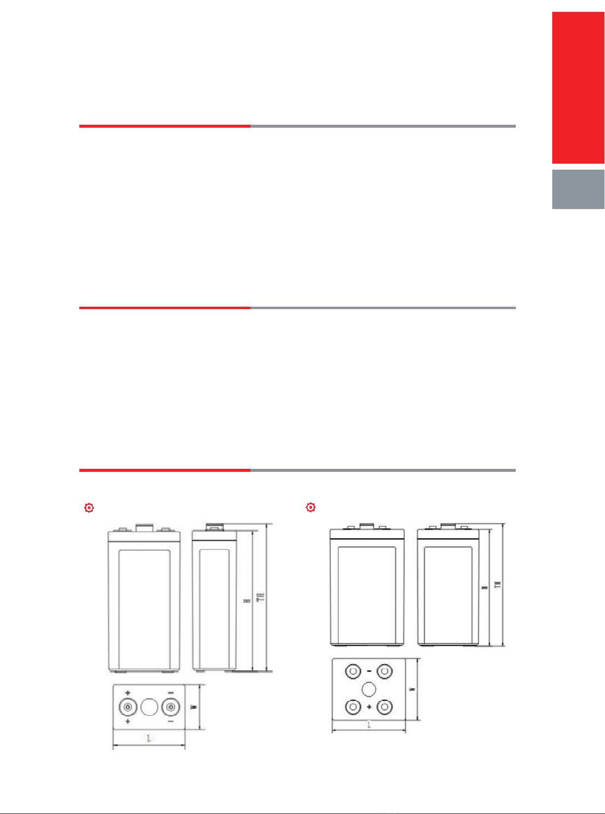
3. Battery Construction ....................................................................................................02
4. General Specification ..................................................................................................03
5. VRLA Technology ........................................................................................................04
Chapter II: Electrical Characteristics
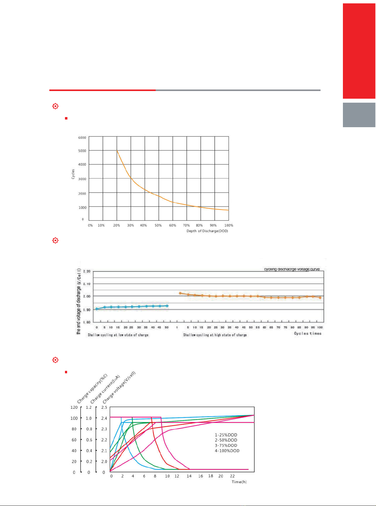
1. Performance Curve ...................................................................................05
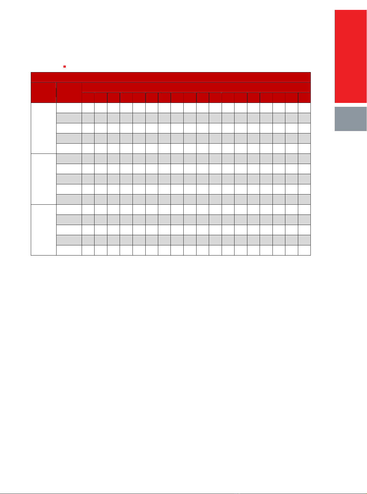
2. Performance Data ........................................................................................................06
Chapter III: Operation and Maintenance
1. Security Instruction ......................................................................................................09
2. Discharge.................................................................................................10
3. Temperature Effect On Battery Capacity .........................................................10
4. Temperature Effect on Battery Service Life.....................................................11
5. Floating Charge And Equalizing Charge .........................................................11
6. Recharge .................................................................................................13
7. Storage..................................................................................14
8. Installation ................................................................................................14
9. Connection ...............................................................................................14
10. Commissioning .........................................................................................15
11. Maintenance .............................................................................................15

Chapter I: Product Introduction
Product Characteristics
Advantages
Design life: 18 years (25℃);
Very long life according to EUROBAT Classification
High discharge performance
High gas recombination efficiency
Maximum charge efficiency
GEL state electrolyte prevents leakage and layering
Low resistance PVC or PF micro-porous separator ensure Low self-discharge rate
Easy installation and handling
Shelf life: 24 months (25℃)
Design features
Positive plates
Negative plates
Separators
Container and Lid
Electrolyte
Terminal posts
Posts sealing
Vents
Plates suspension
Inter-cell connectors
Terminal hardware
Product
In tro d u ctio n
01
Flat pasted plate with lead-calcium-tin grid alloy (radial design);
Flat pasted plate with lead-calcium grid alloy (radial design);
Microporous PVC or PF separator;
High-strength ABS (option: available in Flame Retardant UL94 V0 version);
Gel: SiO
2
gelled sulfuric acid;
High-conductivity terminals with threaded inserts;
Double sealing structure;
One way valve with integrated flame arrestor;
Bottom supported;
Insulated rigid copper;
Stainless steel+Cover.

Main Applications
Telecommunications;
Emergency power;
Renewable Energy Storage Systems;
UPS and EPS units;
Electrical Power plants and substation;
Transportation.
Standards
IEC60896-21/22: 2004
DIN43539-T5 1984
IEC61427-2005
YD/T1360-2005
GB/T 22473-2008
Battery Construction
GFMJ-200 and GFMJ-300 GFMJ-400/500/600
Product
In tro d u ctio n
02

GFMJ-800 and 1000
General Specification
GFMJ series
Table 1-1 GFMJ series general specification
Battery Type
Rated
Voltage
(V)
Rated
Capacity
(Ah,25℃)
Dimensions (mm)
Weight
(kg)
Short
Circuit
Current (A)
Internal
Resistance
(mΩ,25℃)
Terminal
Type
Terminal
Layout
C
10
1.80V/cell
L W H TH
GFMJ-200 2 200 171 107 334 344 14.8 2800 0.68 M8×Φ18
F
GFMJ-300 2 300 171 151 334 344 21.3 3600 0.54 M8×Φ18
F
GFMJ-400 2 400 211 175 334 344 30 4350 0.45 M8×Φ18
H
GFMJ-500 2 500 243 174 334 344 35.5 5020 0.39 M8×Φ18
H
GFMJ-600 2 600 302 177 334 344 44 5860 0.33 M8×Φ18
H
GFMJ-800 2 800 410 175 334 344 60 6900 0.28 M8×Φ18
K
GFMJ-1000 2 1000 478 175 334 344 71 8000 0.24 M8×Φ18
K
Terminal Layout
Terminal Type
Product
In tro d u ctio n
03

VRLA Technology
The electrochemical reaction of batteries in charge and discharge process as follows:
Discharge
PbO
2
+2H
2
SO
4
+ Pb PbSO
4
+ 2H
2
O + PbSO
4
Charge
In the final stage of charge process, active substance in positive plate is fully transformed to lead
dioxide, but negative plate has not reached fully charged stage, the process of active substance in
negative plate transforming to spongy lead is not finished, oxygen gas generated in positive plate
reaches the negative plate through separator pores and then reacts with active substance in
negative plate, resulting depolarized state in negative plate, and restraining the generation of
hydrogen.
Principle of the oxygen reduction cycle as follows:
Product
In tro d u ctio n
04

Chapter II: Electrical Characteristics
Performance Curve
Cycle performance curve ( 25℃)
Figure 2-1 GFMJ series battery cycle times curve at different depth of discharge
Voltage curve of simulation wind energy system cycle application
Figure 2-3 Voltage curve of simulation wind energy system cycle application
Charge characteristic curve under different depth of discharge ( 25℃)
Figure 2-4 Charge characteristic curve under different depth of discharge
Electrical Characteristics
05

Performance Data
Constant current discharge data
Table 2-2 GFMJ Battery Constant Current Discharge Data Sheet (Amperes, 25 ℃)
Constant Current Discharge Data Sheet (25℃)-------Amperes(A)
Battery Type
End Voltage
(V/cell)
Discharge Time
5min
10min
15min
20min
30min
1 h
2 h
3 h
5 h
6 h
8 h
10 h
20 h
24 h
48 h
100 h
120 h
240 h
GFMJ-200
1.65 340
310
288
260
202
125
75
55
38
34.00
26.60
22.10
11.20
9.45
4.86
2.51
2.18
1.16
1.70 320
295
260
227
190
123
73.7
54.4
37.1
32.20
25.80
21.30
10.80
9.20
4.86
2.51
2.18
1.16
1.75 300
279
248
219
184
121
72.3
53.6
36.4
31.70
25.30
20.90
10.60
9.10
4.86
2.51
2.18
1.16
1.80 280
265
229
202
170
112
69.4
51.2
35
30.50
24.30
20.00
10.20
9.02
4.86
2.51
2.18
1.16
1.85 240
229
209
189
159
108
65.3
48.0
32.9
28.60
22.80
18.90
9.80
8.90
4.86
2.51
2.18
1.16
GFMJ-300
1.65 510
465
432
390
303
188
112.5
82.5
57
51.00
39.90
33.75
16.95
14.22
7.29
3.75
3.27
1.74
1.70 480
443
390
341
285
185
110.6
81.6
55.65
48.30
38.70
31.95
16.65
14.05
7.29
3.75
3.27
1.74
1.75 450
419
372
329
276
182
108.5
80.4
54.6
47.55
37.95
31.35
16.50
13.90
7.29
3.75
3.27
1.74
1.80 420
398
344
303
255
168
104.1
76.8
52.5
45.75
36.45
30.00
16.20
13.72
7.29
3.75
3.27
1.74
1.85 360
344
314
284
239
162
98.0
72.0
49.4
42.90
34.20
28.35
15.30
13.20
7.29
3.75
3.27
1.74
GFMJ-400
1.65 680
620
576
520
404
250
150
110
76
68.00
53.20
45.00
22.60
19.02
9.72
5.00
4.36
2.32
1.70 640
590
520
454
380
246
147.4
108.8
74.2
64.40
51.60
42.60
22.20
18.68
9.72
5.00
4.36
2.32
1.75 600
558
496
438
368
242
144.6
107.2
72.8
63.40
50.60
41.80
22.00
18.58
9.72
5.00
4.36
2.32
1.80 560
530
458
404
340
224
138.8
102.4
70
61.00
48.60
40.00
21.60
18.43
9.72
5.00
4.36
2.32
1.85 480
458
418
378
318
216
130.6
96.0
65.8
57.20
45.60
37.80
20.40
17.60
9.72
5.00
4.36
2.32
GFMJ-500
1.65 850
775
720
650
505
313
187.5
137.5
95
85.00
66.50
56.25
28.25
23.75
12.15
6.25
5.45
2.90
1.70 800
738
650
568
475
308
184.3
136
92.75
80.50
64.50
53.25
27.75
23.30
12.15
6.25
5.45
2.90
1.75 750
698
620
548
460
303
180.8
134
91
79.25
63.25
52.25
27.50
23.10
12.15
6.25
5.45
2.90
1.80 700
663
573
505
425
280
173.5
128
87.5
76.25
60.75
50.00
27.00
23.10
12.15
6.25
5.45
2.90
1.85 600
573
523
473
398
270
163.3
120.0
82.3
71.50
57.00
47.25
25.50
22.00
12.15
6.25
5.45
2.90
GFMJ-600
1.65 1020
930
864
780
606
375
225
165
114
102.00
79.80
67.50
33.90
27.72
14.58
7.50
6.54
3.48
1.70 960
885
780
681
570
369
221.1
163.2
111.3
96.60
77.40
63.90
33.30
27.72
14.58
7.50
6.54
3.48
1.75 900
837
744
657
552
363
216.9
160.8
109.2
95.10
75.90
62.70
33.00
27.72
14.58
7.50
6.54
3.48
1.80 840
795
687
606
510
336
208.2
153.6
105
91.50
72.90
60.00
32.40
27.72
14.58
7.50
6.54
3.48
1.85 720
687
627
567
477
324
195.9
144.0
98.7
85.80
68.40
56.70
30.60
26.40
14.58
7.50
6.54
3.48
GFMJ-800
1.65 1360
1240
1152
1040
808
500
300
220
152
136.00
106.40
90.00
45.20
38.35
19.44
10.00
8.72
4.64
1.70 1280
1180
1040
908
760
492
294.8
217.6
148.4
128.80
103.20
85.20
44.40
38.00
19.44
10.00
8.72
4.64
1.75 1200
1116
992
876
736
484
289.2
214.4
145.6
126.80
101.20
83.60
44.00
37.40
19.44
10.00
8.72
4.64
1.80 1120
1060
916
808
680
448
277.6
204.8
140
122.00
97.20
80.00
43.20
36.96
19.44
10.00
8.72
4.64
1.85 960
916
836
756
636
432
261.2
192.0
131.6
114.40
91.20
75.60
40.80
36.25
19.44
10.00
8.72
4.64
Electrical Characteristics
06

Table 2-2 GFMJ 2V Battery Constant Current Discharge Data Sheet (Amperes, 25 ℃)
Constant Current Discharge Data Sheet (25℃)-------Amperes(A)
Battery Type
End Voltage
(V/cell)
Discharge Time
5min
10min
15min
20min
30min
1 h
2 h
3 h
5 h
6 h
8 h
10 h
20 h
24 h
48 h
100 h
120 h
240 h
GFMJ-1000
1.65 1700
1550
1440
1300
1010
625
375
275
190
170.00
133.00
112.50
56.50
47.80
24.30
12.50
10.90
5.80
1.70 1600
1475
1300
1135
950
615
368.5
272
185.5
161.00
129.00
106.50
55.50
47.40
24.30
12.50
10.90
5.80
1.75 1500
1395
1240
1095
920
605
361.5
268
182
158.50
126.50
104.50
55.00
47.10
24.30
12.50
10.90
5.80
1.80 1400
1325
1145
1010
850
560
347
256
175
152.50
121.50
100.00
54.00
46.80
24.30
12.50
10.90
5.80
1.85 1200
1145
1045
945
795
540
326.5
240.0
164.5
143.00
114.00
94.50
51.00
46.50
24.30
12.50
10.90
5.80
Constant power discharge data
Table 2-4 GFMJ Battery Constant Power Discharge Data Sheet (W/cell, 25℃)
Constant Power Discharge Data Sheet (25℃)-------Watt (W)
Battery Type
End Voltage
(V/cell)
Discharge Time
5min
10min
15min
20min
30min
1 h
2 h
3 h
5 h
6 h
8 h
10 h
20 h
24 h
48 h
100 h
120 h
240 h
GFMJ-200
1.65 594
551
518
471
369
232
140
104
72
50.10
40.00
33.00
18.30
16.90
9.72
5.00
4.40
2.34
1.70 569
534
475
418
351
230
139
104
71
48.60
38.50
31.90
18.30
16.70
9.72
5.00
4.40
2.34
1.75 547
515
462
410
346
229
138
103
70
46.90
37.20
30.70
18.30
16.50
9.72
5.00
4.40
2.34
1.80 523
498
434
383
325
214
135
99
68
45.20
35.80
30.00
18.30
16.10
9.72
5.00
4.40
2.34
1.85 458
439
402
366
309
211
128.0
94.0
65.0
42.90
34.10
28.30
17.60
15.30
9.72
5.00
4.40
2.34
GFMJ-300
1.65 891
827
777
707
554
348
210
156
108
75.15
60.00
49.50
25.35
27.45
14.58
7.50
6.60
3.51
1.70 854
801
713
627
527
345
208.5
156
106.5
72.90
57.75
47.85
25.05
27.45
14.58
7.50
6.60
3.51
1.75 821
773
693
615
519
344
207
154.5
105
70.35
55.80
46.05
24.75
27.45
14.58
7.50
6.60
3.51
1.80 785
747
651
575
488
321
202.5
148.5
102
67.80
53.70
45.00
24.15
27.45
14.58
7.50
6.60
3.51
1.85 687
659
603
549
464
317
192.0
141.0
97.5
64.35
51.15
42.45
22.95
26.40
14.58
7.50
6.60
3.51
GFMJ-400
1.65 1188
1102
1036
942
738
464
280
208
144
100.20
80.00
66.00
33.80
30.60
19.44
10.00
8.80
4.68
1.70 1138
1068
950
836
702
460
278
208
142
97.20
77.00
63.80
33.40
29.80
19.44
10.00
8.80
4.68
1.75 1094
1030
924
820
692
458
276
206
140
93.80
74.40
61.40
33.00
29.20
19.44
10.00
8.80
4.68
1.80 1046
996
868
766
650
428
270
198
136
90.40
71.60
60.00
32.20
28.90
19.44
10.00
8.80
4.68
1.85 916
878
804
732
618
422
256.0
188.0
130.0
85.80
68.20
56.60
30.60
28.30
19.44
10.00
8.80
4.68
GFMJ-500
1.65 1485
1378
1295
1178
923
580
350
260
180
125.25
100.00
82.50
42.25
39.80
24.30
12.50
11.00
5.85
1.70 1423
1335
1188
1045
878
575
347.5
260
177.5
121.50
96.25
79.75
41.75
39.40
24.30
12.50
11.00
5.85
1.75 1368
1288
1155
1025
865
573
345
257.5
175
117.25
93.00
76.75
41.25
39.00
24.30
12.50
11.00
5.85
1.80 1308
1245
1085
958
813
535
337.5
247.5
170
113.00
89.50
75.00
40.25
38.60
24.30
12.50
11.00
5.85
1.85 1145
1098
1005
915
773
528
320.0
235.0
162.5
107.25
85.25
70.75
38.25
36.90
24.30
12.50
11.00
5.85
Electrical Characteristics
07

Table 2-4 GFMJ Battery Constant Power Discharge Data Sheet (W/cell, 25℃)
Constant Power Discharge Data Sheet (25℃)-------Watt (W)
Battery Type
End Voltage
(V/cell)
Discharge Time
5min
10min
15min
20min
30min
1 h
2 h
3 h
5 h
6 h
8 h
10 h
20 h
24 h
48 h
100 h
120 h
240 h
GFMJ-600
1.65 1782
1653
1554
1413
1107
696
420
312
216
150.00
120.00
99.00
50.70
48.70
29.16
15.00
13.20
7.02
1.70 1707
1602
1425
1254
1053
690
417
312
213
146.00
116.00
95.70
50.10
48.10
29.16
15.00
13.20
7.02
1.75 1641
1545
1386
1230
1038
687
414
309
210
141.00
112.00
92.10
49.50
47.50
29.16
15.00
13.20
7.02
1.80 1569
1494
1302
1149
975
642
405
297
204
136.00
107.00
90.00
48.30
46.50
29.16
15.00
13.20
7.02
1.85 1374
1317
1206
1098
927
633
384.0
282.0
195.0
129.00
102.00
84.90
45.90
44.50
29.16
15.00
13.20
7.02
GFMJ-800
1.65 2376
2204
2072
1884
1476
928
560
416
288
200.00
160.00
132.00
67.60
63.40
38.88
20.00
17.60
9.36
1.70 2276
2136
1900
1672
1404
920
556
416
284
194.00
154.00
128.00
66.80
63.00
38.88
20.00
17.60
9.36
1.75 2188
2060
1848
1640
1384
916
552
412
280
188.00
149.00
123.00
66.00
62.40
38.88
20.00
17.60
9.36
1.80 2092
1992
1736
1532
1300
856
540
396
272
181.00
143.00
120.00
64.40
61.80
38.88
20.00
17.60
9.36
1.85 1832
1756
1608
1464
1236
844
512.0
376.0
260.0
172.00
136.00
113.00
61.20
60.70
38.88
20.00
17.60
9.36
GFMJ-1000
1.65 2970
2755
2590
2355
1845
1160
700
520
360
251.00
200.00
165.00
84.50
91.50
48.60
25.00
22.00
11.70
1.70 2845
2670
2375
2090
1755
1150
695
520
355
243.00
193.00
160.00
83.50
91.50
48.60
25.00
22.00
11.70
1.75 2735
2575
2310
2050
1730
1145
690
515
350
235.00
186.00
154.00
82.50
91.50
48.60
25.00
22.00
11.70
1.80 2615
2490
2170
1915
1625
1070
675
495
340
226.00
179.00
150.00
80.50
91.50
48.60
25.00
22.00
11.70
1.85 2290
2195
2010
1830
1545
1055
640.0
470.0
325.0
215.00
171.00
142.00
76.50
88.00
48.60
25.00
22.00
11.70
Electrical Characteristics
08

Chapter III: Operation and Maintenance
Security Instruction
Please read these instructions carefully in order to ensure correct, safe and effective operation.
This manual provides you very important guidance for installation and operation, which will
guarantee your equipment with optimal performance and longer service life.
For your safety, please do not open the batteries;
As batteries contain lead which can potentially be harmful to the environment and health, and
as batteries are connected to electricity, they must be installed, maintained and replaced by
skilled personnel only.
Used batteries must be recycled and disposed properly as improper disposal of batteries is
harmful to the environment and health. Used batteries shall be properly disposed following
relative regulations and laws.
It is strictly forbidden to mix batteries with different specifications, manufacturers and
capacities.
All installations must comply with the safety regulations and norms. Read through our
Operation Guide / Safety Instructions before starting any installation work.
Notices
Warning Electrical shock
Protective eyewear and
clothing required
Keep children away from
the batteries
No short circuit
No flames and sparks
Recycle Proper disposal Read instructions
Electrolyte is highly
corrosive
Security Instruction
09

Discharge
End voltage with different discharge rate must be less than the specified value. Charge the battery
as soon as possible after discharge.
In order to extend the service life, the depth of discharge should be less than 60% of the Nominal
capacity. The discharge over 60% DOD is deep discharge and would shorten the service life.
Under the temperature of -25℃, discharge over 60% DOD is prohibited, except protective
measure is adopted such as raising temperature.
Temperature
The operation temperature range is -20℃~55℃. All the performance data is measured at ambient
temperature of 25℃.The optimal temperature is 25℃±5℃, over high temperature would shorten
the service life and over low temperature would lower the capacity available. The highest
acceptable temperature is 55℃.
Temperature Effect On Battery Capacity
Figure 3-1 temperature effect on battery capacity
Operation and maintenance
10

Temperature Effect on Battery Design Life
Figure 3-2 GFMJ series temperature effect on battery design life curve
Floating Charge and Equalizing charge
Floating charge
Floating operation is the best operation condition for battery. In floating operation, the battery
keep fully charged state, under this condition, battery could reach the longest service life.
Under the temperature of 25℃, recommended floating charge voltage setting value is 2.22
V/cell.
In such method, it take about 24~36h for battery fully charged. For achieving better
performance, the floating charge voltage should be suitable adjusted according to ambient
temperature, temperature compensation coefficient is -3.5mV/℃/cell, for details please refer to
Table 3-1.
Table 3-1 Floating charge voltage under different temperature
Ambient Temperature (℃) Floating Charge Voltage (V/cell)
0 2.32
10 2.28
15 2.26
20 2.24
25 2.22
30 2.20
35 2.18
Operation and maintenance
11

Equalizing charge
Equalizing charge or supplementary charge is needed in the following cases:
After finish installation, before the battery system is put into operation, the battery bank
should be supplementary charged.
The battery is out of work beyond 6 months.
Running in full-floating operation for a long term, but not discharge under more than
40%C
10
capacity, the batteries need an equalizing charge regularly and the equalizing
charge cycle are 6 months to one year.
Recommended charge method as follows:
2.35V/cell with limited current of 0.15 C
10
(A), charge for 8~12 hours (non-continuous
charge is allowed)
Charge voltage shall be adjusted according to the ambient temperature, temperature
compensation coefficient is ±3.5mV/cell/℃, for details please refer to table 3-2.
Table 3-2 Equalizing charge voltage under different temperature
Ambient Temperature (℃) Equalizing Charge Voltage (V/cell)
0 2.43
10 2.39
15 2.37
20 2.35
25 2.33
30 2.31
35 2.29
After equalizing charge, for batteries with voltage lower than 2.18V/cell, we should make the
battery discharged in 0.1C
10
A for 4-6 hours, and then charge the battery with constant voltage
of 2.35V / cell and limited current of 0.15C
10
A.
Operation and maintenance
12

Recharge
Recharge the battery immediately after discharge according to the below method:
Charge the battery with constant current of no more than 0.2C
10
(A), until the battery voltage rises
to 2.33~2.37V/cell, then change to constant voltage charge of 2.33~2.37V/cell until the charge
completed. Any of the following two items can be regarded as the fully charged symbol.
Refer to the required time as table 3-3.
In constant voltage case, the charge current keep unchanged for 3 hours in the final stage of
charge.
Charge voltage shall be adjusted according to the ambient temperature, temperature
compensation coefficient is ±3.5mV/℃/ cell.
Table 3-3 Required charge time in different depth of discharge
Depth of
discharge (%)
Charge current of
constant current
charge(A)
Time for changing constant
current charge to constant
voltage charge(h)
Charge voltage of
constant voltage
charge(V)
Charge time(h)
20
0.1C
20
1.6 2.33 8
0.15C
20
1.2 2.33 6
50
0.1C
20
4.3 2.33 14
0.15C
20
3.3 2.33 12
80
0.1C
20
6.8 2.33 16
0.15C
20
5.5 2.33 14
100
0.1C
20
8.7 2.33 18
0.15C
20
6.8 2.33 16
Storage
The battery should be stored in clean and dry environment .
Storage time: battery is ex-work in fully charged, storage time should be limited, for ensuring
battery performance, storage time please do not exceed following time:
Under 25℃, six months
Under 30℃, three months
Under 40℃, six weeks
The battery supplementary charge method during the storage is: charge battery with 2.35V/cell for
8 to 12 hours.
Operation and maintenance
13

Table 3-4 Open circuit voltage at different charge state
Charge State Voltage(V)/cell
100% ≥2.18
80% ≥2.14
60% ≥2.10
40% ≥2.08
20% ≥2.04
It is necessary to limit the current, and the optimum limiting value is within 0.2C
10
( A ) .
Testing of the open circuit with the storage battery can decide whether it shall be supplementary
charged. If the voltage drops to 2.10V/cell, the battery shall be supplementary charged in time.
Improper maintenance will shorten the battery service life or decrease the service performance.
Abnormal Operation Condition
Unmeant deep discharge, battery can‘t be charged for a long term with small current which is
lower than system requirement, or else, the battery capacity will fall down early.
Battery is discharged fully.
Sulphuric acid is run out completely, only water is left in electrolyte, under this condition recharge
will cause lead pine-tree crystal, it will result that separator is penetrated, thus short circuit is
occurred. Plate sulfating grade is highest, and internal resistance is largest.
Installation
Batteries integrated in equipment should be compliance with the installation instructions, Battery
which is separately installed on rack and cabinets should be connected by bolts to the foundation.
Battery racks or cabinets should be properly installed according to instructions.
Connection
Before connecting, make an overall check of all the batteries and connectors to see whether there
is hardware damage or manufacturing defects, and make sure the right polarity.
Operation and maintenance
14

The charge equipment are in cut-off state and without loads, then connect the positive and
negative terminals to chargers.
During the installation and transit of the battery, use insulted tools, gloves, aprons and safety
glasses, avoiding battery is impacted, do not twist connecting terminals and safety valve in transit.
Placing tools and conductive articles on the battery is strictly prohibited.
Dusty connecting terminal or loose connection will cause battery sparkle, so please keep the
connecting terminals clean and tighten the connectors as per required torque value, but please do
not cause torsional stress to terminals.
Commissioning
Assure battery operation in the clean environment.
Before operation, battery charge voltage must be adjusted as constant value as per ambient
temperature. Such as, at 25℃, charge the battery with 2.23V/cell for 16 to 24 hours, or with
2.33Vpc for 8 to 12 hours;
If the storage condition is serious, adjust charge voltage is necessary.
Maintenance
1. Cleaning Notes:
Battery appearance, terminal area and working environment must be kept clean and dry.
In battery cleaning process, avoid use of electrostatic cleaning tools.
Clean the battery with damp cloth. Do not use of gasoline, alcohol or other organic solvents;
also do not use cloth containing these substances.
2. Inspection and Maintenance
VRLA batteries are not maintenance-free batteries, battery operation process gradually
changes with time. In order to ensure good battery usage, operational management and
control are very important. To understand the operation status of batteries and equipment
and to prevent accidental damage, regular maintenance is required. Periodically check
and record the measurements using the following method for batteries used in UPS system
room and base station (including outdoor station) site.
Operation and maintenance
15

2.1 Monthly Maintenance Inspection Items
Item Content Standard Maintenance
1-Temperature
Detection
1-Measure and record
battery terminal and
container temperature
by using infrared
thermometer.
2-Use infrared
thermometer to measure
ambient temperature.
1-
Ambient Temp:
-20℃~+55℃
2-Recommended
Temperature:
25±5℃
1-Check that the battery temperature
compensation functions are turned on and
that the battery temperature probe is
properly installed.
2-Check that the room temperature
conditioning equipment such as
air-conditioning is turned on.
2- Battery Float
Voltage
Measurement
Measure floating voltage
on positive and negative
terminal of the battery
group with multimeter.
Measurement and
control module
display operating
voltage differences
within 0.05V
If the monitoring module shows
inconsistency even after adjusting, replace
or repair it.
3-Battery
Appearance
Inspect the battery
container for bulging,
leakage and damage.
Normal
Appearance
Confirm the reason for any abnormal
appearance, if it affects normal use,
replace the battery.
Check for dirt stains Clean Appearance Clean dust and dirt with damp cloth
Inspect the connection
cables, terminals, etc.
for oxidation, rust &
other abnormalities
No oxidation, rust If you find oxidation or rust, replace the
connecting wire, and swab terminal with
Vaseline etc.
4- Joints
Use hex or torque
wrench to tighten loose
bolts.
Securely connected
If found bolt loosened, tighten it
1-Battery cables,
terminals clean /
non-corrosive.
2- Follow the installation
sequence: 1. Spring
washers 2. Flat washers
3, Nuts
No evidence of
corrosion
If slight corrosion found after connecting
bar removed, clean it with cloth. If severe
corrosion, replace the connection bar and
clean terminal with sandpaper before
tightening.
5-Safety Valve
Testing
Inspect for white
crystalline or liquid
surrounding the safety
valve.
No crystalline or
liquid surrounding
the safety valve
1-For crystalline, use a dry cloth for
cleaning.
2-If there is crystalline or liquid, clean it
with a dry cloth. Check and tighten the
safety valve
Operation and maintenance
16

2.2 Quarterly Maintenance Inspection Items
In addition to the monthly maintenance items above, inspect the following items:
Item Content Standard Maintenance
1- Measurement of
each battery’s
floating voltage
Measure each battery’s
floating voltage by using
multimeter.
Battery floating
voltage differential
pressure must meet
the following
values:
2V series 90 mV
6V series 240 mV
12V series 480 mV
If there are deviations from the reference
values, first discharge the battery group and
then equalizing charge. After equalizing
charge is completed, change to float charge
and run for two months. If there are still
deviations from the reference values, replace
and recycle the battery.
2-Use the
equalizing charge
to recover the
batteries which
have either lower
capacity or
discharge voltage
than the other
batteries.
Use the equalizing
charge to charge the
battery 10 hours or
more. In case a battery
has a severe deviation
compared to other
batteries, perform
charge / discharge
cycles three times.
Single battery
discharge voltage in
the battery group
must meet the
following values:
2V: 200mV, 6V:
350mV
12V: 600mV
If the battery performance cannot be
recovered, it must be replaced.
2.3 Annual Maintenance Inspection Items
In addition to the quarterly maintenance items above, inspect the following items:
Item Content Standard Maintenance
1- Discharge test
Disconnect the AC, take
load discharge or
discharge online method
to check that discharge
capacity is minimum
30%-40% of nominal
capacity
At the end of
discharge, battery
voltage should be
more than
1.90V/cell,
differential pressure
must meet the
following values:
2V series 200mV
6V series 350mV
12V series 600mV
If the battery voltage is lower
than a voltage reference value or the
differential pressure is greater than the
reference value, discharge the battery,
then equalizing charge, then change to
float charge and run for 1-2 months. If
reference values still exceeded, contact
our technical team for assistance.
2- Capacity Test
Use on-line or off-line
intelligent discharge
device for discharging
batteries until the end
voltage has reached
1.80V / cell
In back-up use the
capacity to be
maintained must be
more than 80% and
in energy storage
use more than 60%
of the reference
capacity
Recovery test: measure and record
various parameters specified in the
monthly / quarterly maintenance items as
well each battery’s end voltage during the
discharge test. If the battery performance
cannot be recovered, replace and re-cycle
the battery.
Operation and maintenance
17

3-Measure and
verify the
controller
parameters
1-Measure the limited
charging current values.
2-Check that the
equalizing charge starts
and ends automatically.
3- Verify the automatic
start of battery discharge
protection.
Actual operation
parameters to meet
with the set
parameters
In case power equipment and/or controller
fails, arrange repair in a due course to
ensure correct battery performance and
avoidance of reduced battery lifetime.
Maintenance notes
Operate and store batteries only in an upright position.
Ensure that the battery installation complies with the design requirements and installation
documents.
Please use only insulated tools during operation and maintenance, any metal objects to be
put on top of the battery is strictly prohibited.
Operation and maintenance
18
This manual suits for next models
7
Table of contents
Other Sacred Sun Camera Accessories manuals

Sacred Sun
Sacred Sun FAJ Series User manual

Sacred Sun
Sacred Sun GFMG Series User manual

Sacred Sun
Sacred Sun FCP Owner's manual

Sacred Sun
Sacred Sun SPG Series User manual

Sacred Sun
Sacred Sun FMJ Series User manual

Sacred Sun
Sacred Sun SP Series User manual

Sacred Sun
Sacred Sun DCS Series User manual

Sacred Sun
Sacred Sun OPzV Series User manual

Sacred Sun
Sacred Sun sp series User manual