5
Equipment description
The micromotor and Apex locator Endus Duo R is a high-precision electronic equipment, modern
and that should be used in endodontics to aid in canal treatments. It is used to measure the real
length of the tooth - (it determines the working length) – until where the instrumentation and lling
will take place, in order for the endodontics treatment to respect the biologic limits of the dental
structure. Combined with the pen for rotatory instrumentation it allows that the micromotor be
manipulated in various patterns, in rotatory mode or reciprocal mode of the instrument.
Main characteristics:
- Easy-access LCD visible panel;
- Activation on the own handpiece;
- Adjustable speed of rotation and torque;
- It has 9 pre-dened programmings;
- Double-frequency apex locator;
- Four modes of operation;
- It allows the use of diverse types of drills and les;
- Automatic reverse by torque and reduction of speed by torque;
- Adjustable direction of rotation (left/right);
- 2 reciprocal systems (VDW e DENTSPLY);
- Automatic bivolt switched power supply which allows the use of the equipment in any voltage
source from 100 to 240V~ - 50/60Hz;
- Rechargeable high capacity Li-ion battery;
- Automatic Power o;
- Low noise and vibration level.
Principles and foundations applied to the proper functioning of the product
Apex Locator: It is understood that the tooth works like a capacitor with the accumulation of
electric charges at the periodontium and on the inside of the radicular canal. The dentine works
as an isolator for the propagation of electric current along all the extension of the radicular canal.
The Apex locators work with the principle of the constancy of electric current between the oral
mucosa and the periodontal ligament. The electronic method considers the dierence on the electric
conductivity of a metallic instrument on the inside of the radicular canal and the conductivity of the
periapical tissue. The electric current existing on the radicular canal would complete the circuit at
the moment that the electrode, le, would touch the tissue uid, indicating the most apical portion
of the radicular canal, “the apical foramen”.
Electric micromotor: Its functioning principle is based on the magnetic eld, which will induce the
rotor to spin when a direct current is applied to its poles.
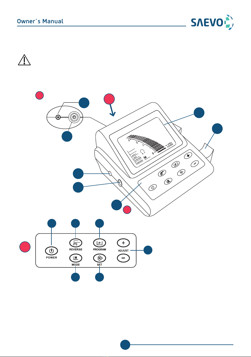
IDENTIFICATION OF EQUIPMENT