SAEVO Max User manual


2
PRESENTATION OF MANUAL
INSTRUCTIONS FOR USE
ATTENTION
Technical Name: Equipment for dental bleaching and photopolymerization of resins
Trade Name: Curing Light Optilight
Model: Max
Brand: Saevo
Manufacturer/Distribuitor:
Alliage S/A Indústrias Médico Odontológica
C.N.P.J. 55.979.736/0001-45 - Insc. Est. 582.002.897.114
Rod. Abrão Assed, Km 53+450m - Cx. Postal 782 CEP 14097-500
Ribeirão Preto - S.P. - Brasil
Telefone +55 (16) 3512-1212
Technical Duties: Ricardo J. Ravaneli
CREA-SP: 5060714523
Registration ANVISA #: 10069210081
For greater safety:
Read and understand all the instructions contained in these instructions for use before installing
or operating this equipment.
Note: These instructions for use must be read by all the operators of this equipment.

3
INDEX
02 PRESENTATION OF MANUAL
04 IDENTIFICATION OF EQUIPMENT
07 MODULES, ACCESSORIES, OPTIONS AND MATERIALS OF CONSUMPTION
09 TECHNICAL SPECIFICATIONS
09 General features
11 Electromagnetic emission
16 Dimensions
17 Packing symbols
17 Product symbols
18 INSTALLATION OF EQUIPMENT
19 OPERATION OF EQUIPMENT
21 PRECAUTION, RESTRICTION AND WARNING
21 Recommendations for the equipment’s conservation
21 Transport conditions, warehousing and operation
22 Sensitivity to predictable environmental conditions in ordinary situations of use
22 Precautions and warnings “during installation” of the equipment
22 Precautions and warnings “during the use” of the equipment
23 Precautions and warnings “after” the use of equipment
23 Precautions and warnings during “cleaning and disinfection” of the equipment
23 Precautions in case of alteration in the functioning of equipment
23 Precautions to be adopted against foreseeable or uncommon risks, related to the deactivation
and abandoning of equipment
24 CORRECTIVE AND PREVENTIVE MAINTENANCE AND PRESERVATION
24 Cleaning, disinfection and sterilization
26 Preventive Maintenance
26 Corrective Maintenance
27 UNFORESEEN EVENTS – SOLUTION OF PROBLEMS
28 EQUIPMENT’S WARRANTY
28 FINAL CONSIDERATIONS

4
IDENTIFICATION OF EQUIPMENT
Dear Customer
This manual is a general presentation of your product and it will give you important details to help
you to solve possible problems.
Please, read it and keep this with you.
IDENTIFICATION
Technical Name: Equipment for dental bleaching and photopolymerization of resins
Trade Name: Curing Light Optilight
Model: Max

5
Description of Equipment
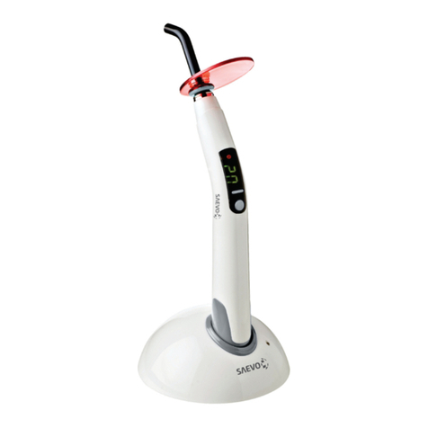
The Optilight Max is the latest generation of the appliances of photoactivation by LED light. This
short name is the acronym for Light Emitting Diode, a totally dierent manner of emitting light,
when compared with the conventional appliances of halogen light. As opposed to the traditional
appliances, which generate light in a wide wave spectrum with great heat, this technology allows
a cold light to be emitted, in the precise wavelength for activating the dierent dental products
to which it applies.
LED technology, recently introduced in Dentistry, has brought countless advantages to the curing
light appliances for direct restorations in composite resin. Besides being innitely more durable, the
LEDs have made the appliances more compact, ergonomic and easy to install and transport. The
emission of cold light at a precise wavelength ensures the polymerization of composites activated
by the canforoquinone, without risks of dental heating, pulpal injury or discomfort for operator
and patients.
The safety and eciency of the LEDs, now with high emission power, are available for all the clinical
procedures which require power of light for photoactivation.
The wavelength of 420nm - 500nm associated with the high power emitted by the Optilight Max
makes the multifunctionality of this appliance feasible:
• Direct restoring procedures: composite resins, ionomers and adhesives.
• Indirect restorations: adhesive cementing of laminates, inlays, esthetic pegs and metal-free crowns.
• Activation of photoactivated materials as sealers, surgical cements and lining bases.
Planned and built using cutting-edge technology, to provide results within the specications
stipulated by the leading world dental authorities.
Endowed with an automatic bivolt switch power supply which allows one to use the equipment at
any power supply voltage between 100 and 240V~ - 50/60Hz.
Digital control in the display on the handpiece itself.
Variance of choice of operating time (5,10,15 and 20 seconds).
It has 3 application modes: Continuous, Ramp and Pulsating:
• Continuous: Maximum and continuous mode of light intensity (same luminosity from start to nish
of the polymerization).
• Ramp: Gradual mode of light intensity; it increases gradually.
• Pulsed: Pulsing mode consisting of cycles which oscillate at a xed frequency.
Physical Principle used by the Equipment
The physical principle is the emission of a cold light to polymerize photosensitive substances, as the
equipment is endowed with a cold light emitter (LED) with a wavelength between 420 and 500nm (blue
light), which has an ideal intensity for being integrated with the canforoquinone.
Indication of the equipment
This equipment is exclusively for dental use, having to be employed and handled by a capacitated
person (professional duly regulated, as per the local legislation of the country) observing the
instructions contained in this manual.
The user is obliged to only use the equipment in perfect conditions and protect himself/herself,
patients and third parties against possible hazards.
Purpose of the equipment
This equipment is exclusively for dental use, with the objective of polymerizing photosensitive
substances through the emission of blue light.
It was developed to be used in several dental procedures such as: restoring procedures, bonding
braces and activating photoactivated materials as sealers, lining bases.
IDENTIFICATION OF EQUIPMENT

6
Advantages oered by Optilight Max:
- More spectrally-selective light than conventional lamps.*
- Cold light, it doesn’t heat up the resin nor the tooth.**
• Light compact equipment that provides handling comfort.
• Low power consumption.
• Longer useful life of the light emitting diode (equivalent to 36.000.000 cycles of 10 seconds).
• It does not use optical lter.
• It does not require forced ventilation, thus avoiding noise emission.
*We noted that the light emitted by the Optilight Max is completely contained within the absorption
interval of the photo starter, therefore it’s 100% used, whereas the conventional equipment running
on halogen lamps has non-used wave-length regions.
** The Optilight Max doesn’t generate heat since it uses light emitting diodes.
The light conductor is removable, made out of high resistance polymer and of easy maintenance.
Light conductor with ber optics, rotating, removable and easy to sterilize, with a front protector of the
tip against scratches and the accumulation of undesirable residue. The reduced weight of the penand
its anatomic design ensure that the professional’s work is more comfortable and practical.
Support for the handpiece, which ensures easy access and handling.
IDENTIFICATION OF EQUIPMENT

7
MODULES, ACCESSORIES, OPTIONS AND MATERIALS OF CON-
SUMPTION
06
01 – Light Conductor
02 – Light Protection Shield
03 – Control Panel
04 - Handpiece
05 – Button to turn on the equipment and activate / interrupt operation
06 – Charging base
07 – Display Window
08 – Time adjustment button
09 – Application mode selection button
10 – Power supply source
11 – Application mode: Continuous, Ramp and Pulsed
01
02
04
10
05
09
08
11
07
03

8
Accessories which come with the product:
The content of this page is for informative purpose, so the equipment can present itself dierent from
the illustration. Therefore, when buying the product, verify the technical compatibility between the
equipment, coupling and accessories.
The use of any part, accessory or material neither specied nor foreseen in those use operation instructions
and it is of the user’s entire responsibility.
MODULES, ACCESSORIES, OPTIONS AND MATERIALS OF CON-
SUMPTION
Light Protection
Shield
Charging base
Power supply sourceLight Conductor

9
TECHNICAL SPECIFICATIONS
Power Supply
Ve: 100 - 240V~ - 50/60Hz
Vs: 5V - 1,5 A
Frequency
50/60Hz
Source Power
6VA
Light Source
1 LED
Light Power
700 mW/cm2
Semicondutor LED (InGaN)
Wavelength
420nm - 500nm
Timer
5,10,15 and 20 seconds
Time Sounder
a “beep” every 05 seconds
Activation
Through the handpiece button
Light Conductor
Optics ber 100% coherent which guarantees the passage of light without loss
Handpiece body
Injected in ABS
Net weight
0,39 kg
Gross weight
0,98 kg
Classication of the Product
As per standard NBR IEC 60601-1
Type of protection against electric shocks
Class II Equipment
General features

10
Applied part
Type B
Degree of protection against harmful penetration of water
IP00
Degree of saf ety of application in the presence of an anesthetic mixture inf lammable with
air, oxygen or nitrous oxide
It is not suitable
Battery of Li-ion
DC 3.7V 2200mAh.
Approximate time for recharging battery
3h
TECHNICAL SPECIFICATIONS

11
Electromagnetic emission
The device is intended for use in the electromagnetic environment specied below. The customer
of the user of the device should assure that it is used in such an environment.
Emission test Compliance Electromagnetic environment – guidance
RF emissions
CISPR 11
Group 1 The device use RF energy only for its
internal function. Therefore, its RF
emissions are very low and are not likely
to cause any interference in nearby
electronic equipment.
RF emission
CISPR 11
Class A
Harmonic emissions
IEC 61000-3-2
Class A The device is suitable for use in all
establishments other than domestic and
those directly connected to the public
low-voltage power supply network that
supplies buildings used for domestic
purposes.
Voltage fluctuations/ flicker
emissions
IEC 61000-3-3
Complies
1) *This product needs special precautions regarding EMC and needs to be installed and put into
service according to the EMC information provided, and this unit can be aected by portable and
mobile RF communications equipment.
2) * Do not use a mobile phone or other devices that emit electromagnetic elds, near the unit.
This may result in incorrect operation of the unit.
3) *Caution: This unit has been thoroughly tested and inspected to assure proper performance
and operation.
4) *Caution: this machine should not be used adjacent to or stacked with other equipment and that
if adjacent or stacked use is necessary, this machine should be observed to verify normal operation
in the conguration in which it will be used.
TECHNICAL SPECIFICATIONS

12
Guidance and manufacture’s declaration – electromagnetic immunity
The device is intended for use in the electromagnetic environment specied below. The customer
or the user of device should assure that it is used in such an environment.
Immunity test IEC 60601 test level Compliance level Electromagnetic
environment - guidance
Electrostatic
discharge (ESD)
IEC 61000-4-2
±8 kV contact
±2 kV, ±4 kV, ±8 kV,
±15 kV air
±8 kV contact
±2 kV, ±4 kV, ±8 kV,
±15 kV air
Floors should be wood,
concrete or ceramic tile.
If floor are covered with
synthetic material, the
relative humidity should be
at least 30%.
Electrical fast
transient/burst
IEC 61000-4-4
±2 kV for power
supply lines
±1 kV for input/
output lines
±2 kV for power
supply lines
±1 kV for input/
output lines
Mains power quality
should be that of a typical
commercial or hospital
environment.
Surge
IEC 61000-4-5
± 1 kV line(s) to line(s)
± 2 kV line(s) to earth
±1 kV line(s) to line(s)
± 2 kV line(s) to earth
Mains power quality
should be that of a typical
commercial or hospital
environment.
Voltage ips, short
interruptions and
voltage variations
on power supply
input lines
IEC 61000-4-11
0% UT; 0.5 cycle
at 0°,45°,90°, 135°,
180°, 225°, 270°, 315°
0% UT ; 1 cycle
70% UT; 25/30 cycle
0% UT; 250/300 cycle
0% UT; 0.5 cycle
at 0°,45°,90°, 135°,
180°, 225°, 270°, 315°
0% UT ; 1 cycle
70% UT; 25/30 cycle
0% UT; 250/300 cycle
Mains power quality
should be that of a typical
commercial or hospital
environment. If the user
of the device requires
continued operation during
power mains interruptions,
it is recommended that the
device be powered from
an uninterruptible power
supply or a battery.
Power frequency
(50Hz/60Hz)
magnetic eld IEC
61000-4-8
30 A/m
50/60Hz
30 A/m
50/60Hz
Power frequency magnetic
fields should be at levels
characteristic of a typical
location in a typical
commercial or hospital
environment.
NOTE Ut is the a.c. mains voltage prior to application of the test level
TECHNICAL SPECIFICATIONS

13
Guidance and manufacture’s declaration – electromagnetic immunity
The device is intended for use in the electromagnetic environment specied below. The customer
or the user of the device should assure that it is used in such an environment.
Immunity
test
IEC 60601
test level
Compliance
level Electromagnetic environment - guidance
Conducted RF
IEC 61000-4-6
Radiated RF
IEC 61000-4-3
3 Vrms
150 kHz to 80 MHz
3 V RMS outside the
ISM band, 6 V RMS in
the ISM bands
3 V/m
80 MHz to 2.7 GHz
80% AM at 1kHz
3 Vrms
150 kHz to 80
MHz
3 V RMS
outside the
ISM band, 6
V RMS in the
ISM bands
3 V/m
80 MHz to 2.7
GHz
80% AM at
1kHz
Portable and mobile RF communications
equipment should be used no closer to any
part of the device, including cables, than
the recommended separation distance
calculated from the equation applicable
to the frequency of the transmitter.
Recommended separation distance
d=0.35√p
d=1.2√p
80MHz to 800MHz:
d=1.2√p
800MHzto 2.7GHz:
d=2.3√p
Where, P is the maximum output power
rating of the transmitter in watts (W)
according to the transmitter manufacturer
and d is the recommended separation
distance.
Field strengths from xed RF transmitters,
as determined by an electromagnetic site
survey, should be less than the compliance
level in each frequency range. Interference
may occur in the vicinity of equipment
marked with the following symbol:
NOTE 1 At 80 MHz and 800 MHz, the higher frequency range applies.
NOTE 2 These guidelines may not apply in all situations. Electromagnetic propagation is
aected by absorption and reection from structures, objects and people.
a - Field strengths from xed transmitters, such as base stations for radio (cellular/cordless)
telephones and land mobile radios, amateur radio, AM and FM radio broadcast and TV broadcast
cannot be predicted theoretically with accuracy. To assess the electromagnetic environment due
to xed RF transmitters, an electromagnetic site survey should be considered. If the measured
eld strength in the location in which the device is used exceeds the applicable RF compliance
level above, the device should be observed to verify normal operation. If abnormal performance
is observed, additional measures may be necessary, such as re-orienting or relocating the device.
b - Over the frequency range 150 kHz to 80 MHz, eld strengths should be less than 3 V/m.
TECHNICAL SPECIFICATIONS

14
Recommended separation distances between portable and mobile RF communications equipment
and the device
The device is intended for use in an electromagnetic environment in which radiated RF disturbances
are controlled. The customer or the user of the device can help prevent electromagnetic
interference by maintaining a minimum distance between portable and mobile RF communications
equipment (transmitters) and the device as recommended below, according to the maximum
output power of the communications equipment.
Rated maximum
output power of
transmitter
(W)
Separation distance according to frequency of transmitter
(m)
150 kHz to 80 MHz
d= 1,2√p
80 MHz to 800 MHz
d= 1,2√p
800 MHz to 2.7 GHz
d= 2,3√p
0,01 0,12 0,12 0,23
0,1 0,38 0,38 0,73
1 1,2 1,2 2,3
10 3,8 3,8 7,3
100 12 12 23
For transmitters rated at a maximum output power not listed above, the recommended separation
distance d in metres (m) can be estimated using the equation applicable to the frequency of
the transmitter, where P is the maximum output power rating of the transmitter in watts (W)
according to the transmitter manufacturer.
NOTE 1 At 80 MHz and 800 MHz, the separation distance for the higher frequency range applies.
NOTE 2 These guidelines may not apply in all situations. Electromagnetic propagation is aected
by absorption and reection from structures, objects and people.
TECHNICAL SPECIFICATIONS

15
Guidance and manufacturer’s declaration - electromagnetic immunity
The device is intended for use in the electromagnetic environment specied below. The customer
or the user of the device, should assure that it is used in such an environment.
Test
frequency
(MHz)
Band a)
(MHz)
Service a) Modulation b) Maximum
power
(W)
Distance
(m)
Immunity
teste level
(V/m)
385 380 - 390 TETRA 400
Pulse
modulation b)
18 Hz
1,8 0,3 27
450 430 - 470 GMRS 460,
FRS 460
FM C)
± 5 kHz
deviation
1 kHz sine
2 0,3 28
710
704 - 787 LTE Band 13, 17
Pulse
modulation b)
217 Hz
0,2 0,3 9
745
780
810
800 - 960
GSM 800/900 TETRA
800, iDEN 820, CDMA
850, LTE Band 5
Pulse
modulation b)
18 Hz
2 0,3 28
870
930
1 720
1 700 -
1 990
GSM 1800; CDMA
1900; GSM 1900;
DECT; LTE Band 1, 3,
4, 25; UMTS
Pulse
modulation b)
217 Hz
2 0,3 28
1 845
1 970
2 450 2 400 -
2 570
Bluetooth, WLAN,
802.11 b/g/n, RFID
2450, LTE Band 7
Pulse
modulation b)
217 Hz
2 0,3 28
5 240
5 100 -
5 800
WLAN 802. 11
a/n
Pulse
modulation b)
217 Hz
0,2 0,3 95 500
5 785
NOTE if necessary to achieve the immunity test level, the distance between the transmitting antenna and the me equipment or
me system may be reduced to 1 m. The 1 m test distance is permitted by IEC 61000-4-3.
a) For some services, only the uplink frequencies are included.
b) The carrier shall be modulated using a 50% duty cycle square wave signal.
c) As an alternative to FM modulation, 50% pulse modulation at 18 Hz may be used because while it does not represent actual
modulation, it would be worst case.
The MANUFACTURER should consider reducing the minimum separation distance, based on RISK MANAGEMENT, and using
higher IMMUNITY TEST LEVELS that are appropriate for the reduced minimum separation distance. Minimum separation
distances for higher IMMUNITY TEST LEVELS shall be calculated using the following equation:
Where P is the maximum power in W, d is the minimum separation distance in m, and E is the IMMUNITY TEST LEVEL in V/m.
TECHNICAL SPECIFICATIONS

16
Dimensions (mm)
TECHNICAL SPECIFICATIONS

17
Packing symbols
Product symbols
Stacking Limit by number Keep dry
This side Up Keep away from sunlight
Fragile, handle with care Temperature limitation
Type B General warning
Attention Recyclable
Refer to the instruction manual
Grounding (at several points of the
equipment) indicates the condition
of being grounded
Serial number Model Number
Manufacturing date Manufacturer
15
TECHNICAL SPECIFICATIONS

18
INSTALLATION OF THE EQUIPMENT
Charge the battery during 08 hours
before using the equipment for the
rst time.
• For your safety the Optilight Max has an
automatic bivolt power supply source of 100V~
- 240V~ - 50/60Hz.
• Connect the cable of the power supply source
(12) to the charging base (06) and the power
supply source (10) in the socket.
• Insert the light conductor (01) in the
handpiece (04).
• Remove the protection cover (13) from the
light conductor.
• Insert the light protection shield (02) in
the light conductor and place the assembled
equipment in the charging base.
02
13
01
10
04
06
12

19
OPERATION OF EQUIPMENT
• Press the button (05) to turn on the equipment.
• Select the application mode pressing the selection button (09), of which the variations are:
- Continuous: Maximum and continuous mode of light intensity (same luminosity from start to nish of
the polymerization).
- Ramp: Gradual mode of light intensity; it increases gradually.
- Pulsed: Pulsing mode consisting of cycles which oscillate at a xed frequency.
The application mode chosen will be viewed in the sequence of LEDs (15).
• In order to schedule the time press the button (08) and choose the time 5 thru 20 seconds, which will
be viewed in the display (07).
• After selecting the mode of application and the choice of time, take the handpiece to the patient’s
mouth and position the light guide at a safe distance.
• In order to start the polymerization cycle, press the start button (05). To interrupt it Just activate
it again.
09
08
15
07
Hand piece
INCORRECT
positioning for
battery charging.
Hand piece
CORRECT
positioning for
battery charging.
Continuous
Ramp
Pulsed
14
05

20
OPERATION OF EQUIPMENT
Application types: Continuous, Ramp and Pulsed
•Continuous:
Maximum and continuous mode of light intensity
(same luminosity from start to finish of the
polymerization).
• Maximum power = 1200 mW/cm²*
• Ramp:
Gradual mode of light intensity, it increases
gradually.
•Gradual increase = 500 - 1200 mW/cm²*
• Pulsed:
Pulsing mode consisting of cycles which oscillate
at a xed frequency.
• On/o every 1sec. maximum power =
1200 mW/cm²*
* Tolerance is ± 200 mW/cm²
ATTENTION:
- Recharge the battery when one of the LED continuous, ramp and pulsed are blinking;
- Keep the handpiece in the charging base (connected to the mains power) when not using;
- When the LED of the charging base (14) is indicating red, the battery is being charged;
- The approximate recharging time is 3 hours. After recharging the LED in the charging base
(14) it will change to green, indicating the complete recharging;
- The battery does not have a memory eect and can be recharged even if it is not completely
discharged.
Table of contents
Other SAEVO Dental Equipment manuals
Popular Dental Equipment manuals by other brands

Aseptico
Aseptico ADU-04ST Operation and maintenance instruction manual

DENTAURUM
DENTAURUM Herbst I Instructions for use

Dentsply Sirona
Dentsply Sirona X-Smart IQ Directions for use

Pelton & Crane
Pelton & Crane 1500 Use & care manual

KaVo
KaVo ProXam iP Instructions for use

VHF
VHF Z4 Original operating instructions

Nakanishi
Nakanishi Espert 500 Operation manual

iTero
iTero Element with Invisalign Training Guidebook

Komet
Komet H254 Series Instructions for use

Ivoclar Vivadent
Ivoclar Vivadent Ivomat IP3 operating instructions

KaVo
KaVo K4 operating instructions

Dentsply Maillefer
Dentsply Maillefer CALAMUS DUAL Directions for use