SAF Integra-X User manual

SAF Tehnika JSC 1
User manual
Integra-X
VER 1.2
FW 3.14.14

SAF Tehnika JSC 2
Proprietary notice
The information presented in this guide is the property of SAF Tehnika, JSC. No part of this
document may be reproduced or transmitted without proper permission from SAF Tehnika,
JSC.
The specifications or information contained in this document are subject to change without
notice due to the continuing introduction of design improvements. If there is any conflict
between this document and compliance statements, the latter will supersede this document.
SAF Tehnika, JSC has no liability for typing errors in this document or damages of any kind that
result from the use of this document.
To get up to date information about accessories and their availability, please contact a sales
representative.
FODU does not contain serviceable parts. Warranty will not be applicable in
the event FODU has been hermetically unsealed.
SAF Tehnika, JSC is not responsible for any radio or TV interference caused
by unauthorized modifications to this equipment. Such modifications could
void the user's authority to operate the equipment.
This device complies with part 15 of the FCC Rules. The operation is subject to the following
two conditions: (1) This device may not cause harmful interference, and (2) this device must
accept any interference received, including interference that may cause undesired operation.
Note
: This equipment has been tested and found to comply with the limits for a Class B digital
device, pursuant to part 15 of the FCC Rules. These limits are designed to provide reasonable
protection against harmful interference in a residential installation. This equipment generates,
uses, and can radiate radio frequency energy and, if not installed and used in accordance with
the instructions, may cause harmful interference to radio communications. However, there is
no guarantee that interference will not occur in a particular installation. If this equipment does
cause harmful interference to radio or television reception, which can be determined by turning
the equipment off and on, the user is encouraged to try to correct the interference by one or
more of the following measures:
Reorient or relocate the receiving antenna.
Increase the separation between the equipment and receiver.
Connect the equipment into an outlet on a circuit different from the one connected to the
receiver.
Consult the dealer or an experienced radio/TV technician for help.
This device complies with Industry Canada licence-exempt RSS standard(s). The operation is
subject to the following two conditions: (1) this device may not cause interference, and (2) this
device must accept any interference, including interference that may cause undesired
operation of the device.
Le présent appareil est conforme aux CNR d'Industrie Canada applicables aux appareils radio
exempts de licence. L'exploitation est autorisée aux deux conditions suivantes : (1) l'appareil
ne doit pas produire de brouillage, et (2) l'utilisateur de l'appareil doit accepter tout brouillage
radioélectrique subi, même si le brouillage est susceptible d'en compromettre le
fonctionnement.
Copyright Notice
Copyright © 2019 SAF Tehnika, JSC. All rights reserved.

SAF Tehnika JSC 3
Contents
: OVERVIEW............................................................................................ 5
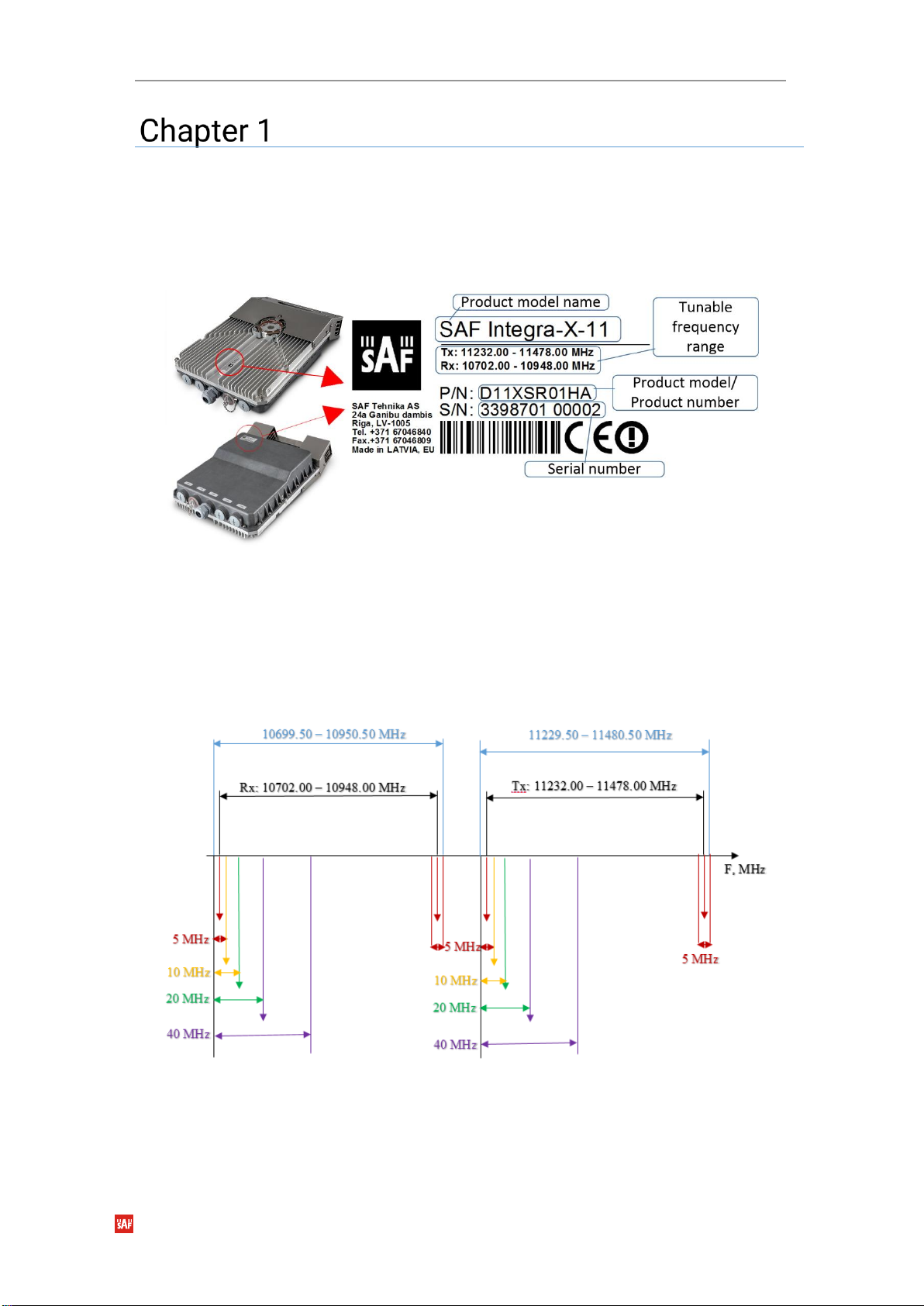
Labeling ............................................................................................................... 5
Microwave Radiation .......................................................................................... 7
: INSTALLATION .................................................................................... 8
Initial setup in indoor environment upon delivery (“bench test”).................... 9
Integra-X FODU: attaching to the antenna ...................................................... 11
Setting link polarization................................................................................ 12
Attaching FODU to the antenna ................................................................... 12
Grounding connection .................................................................................. 14
Power connections ....................................................................................... 14
Note on antenna and XPIC alignment ......................................................... 15
Connecting FO interface using a fiber conduit kit.......................................... 15
WEB GUI ............................................................................................... 17
Initial configuration........................................................................................... 17
Powering Integra-X FODU and connecting to PC ....................................... 17
Connecting Integra-X power supply ................................................................ 18
System requirements.................................................................................... 21
Ethernet management connection configuration ...................................... 22
Accessing Web GUI....................................................................................... 22
Main page.......................................................................................................... 24
Modifying basic system parameters........................................................... 25
Over The Air....................................................................................................... 33
Over The Air Radio Configuration....................................................... 33
Networking ........................................................................................................ 37
Networking Ethernet VLAN................................................................. 37
Networking Ethernet Port status and configuration......................... 39
Networking Ethernet Rate limit........................................................... 41
Networking Ethernet MAC address table .......................................... 43
Performance...................................................................................................... 45
Performance Alarm Alarm status ...................................................... 45
Performance Alarm Alarm event log.................................................. 46
Performance Alarm Sensor configuration......................................... 49
Performance Alarm Alarm threshold configuration ......................... 51
Performance Monitoring Performance graph................................... 53
Performance Monitoring Performance log ....................................... 55
Performance Ethernet Ethernet switch statistics............................. 56
Performance Ethernet Actual throughput ......................................... 61
Performance Ethernet QoS statistics ................................................ 62
Performance Over The Air Equalizer graph ....................................... 63
Performance Over The Air Constellation diagram............................ 64
Performance Over The Air Rx spectrum ............................................ 66
Performance Over The Air Modem performance ............................. 68
System ............................................................................................................... 69
System FW Firmware upgrade ........................................................... 69
System Configuration IP configuration ............................................. 72
System Configuration SNMP configuration ...................................... 74

SAF Tehnika JSC 4
System Configuration Configuration file ........................................... 77
System Configuration Users configuration ....................................... 80
System Configuration System configuration .................................... 82
System Configuration System services............................................. 83
System Diagnostic Loopback configuration ..................................... 86
System Diagnostic Download troubleshooting file........................... 88
System Tools License management.................................................. 90
System Tools Console ........................................................................ 92
System About About System.............................................................. 93
System About Copyright ..................................................................... 94
System About Inventory...................................................................... 95
: COMMAND LINE INTERFACE........................................................... 96
Connecting to serial RS232 interface.............................................................. 96
Connecting to SSH............................................................................................ 98
Connecting to Telnet ........................................................................................ 99
: FUNCTIONAL DESCRIPTION ..........................................................100
ACM - Adaptive Coding and Modulation.......................................................100
Adaptive equalizer ..........................................................................................101
FTP directory ...................................................................................................101
RADIUS authentication ...................................................................................102
Configuration of the Radius server authentication ..................................102
Assigning administrator rights to RADIUS user .......................................103
: TOOLS ..............................................................................................105
Link Layer Discovery tool ...............................................................................105
MIB files...........................................................................................................110
: INTERFACES ....................................................................................111
RJ-45 port ........................................................................................................111
2-wire DC power port ......................................................................................112
SFP ports .........................................................................................................113
USB port...........................................................................................................113
RSSI LED ..........................................................................................................114
RSSI/audio port...............................................................................................115
Grounding connection ....................................................................................118
Appendix A: Technical specifications...............................................................119
ABBREVIATIONS.................................................................................................125
CONTACTS..........................................................................................................127

INTEGRA-X User Manual OVERVIEW
SAF Tehnika JSC 5
: OVERVIEW
Labeling
Each device has 2 identical labels: 1) on the front and 2) on the back of the device casing (
Figure
1-1
).
The label contains the following information - see a sample in
Figure 1-1 Integra-X labels
.
Figure 1-1 Integra-X labels
Product model name - “SAF Integra-X-11”. Number in the end indicates frequency band
supported by the device, in the example above it is 11 GHz.
The tunable frequency range of the particular unit. An example below shows available central
frequency range for 5 MHz channel bandwidth (
Figure 1-2
).
Integra-X label (
Figure 1-1
) indicates tunable Tx/Rx frequency range for 5MHz bandwidth, note
that frequency range is set from the central frequency of the first 5 MHz channel to the central
frequency of the last 5 MHz channel.
Figure 1-2 The central frequency range for 5MHz bandwidth for 11GHz high
side radio.

INTEGRA-X User Manual OVERVIEW
SAF Tehnika JSC 6
Product Number / Model Number (P/N or M/N)(D11XSR01HA): product/model number
contains various information about the unit. See the translation below:
“D11X” - designates Integra-X 11 GHz product;
“S”- designates Integra-X without an integrated antenna;
“R” –XPIC full license allowing unlimited 2.2 Gbps capacity (112MHz/4096QAM);
“K”- XPIC 1 Gbps license; *Contact SAF representatives for detailed licensing
information
“01”- designates the version number of the radio;
“H”- designates high side radio;
“L”- low side radio
“A”- designates radio diapason subband.
Serial Number (339870100002): the serial number uniquely identifies the unit.

INTEGRA-X User Manual OVERVIEW
SAF Tehnika JSC 7
Microwave Radiation
Figure 1-3 Microwave radiation exposure diagram
Integra-X conforms to both occupational and general public exposure limit guidelines and
restrictions to time-varying electric, magnetic and electromagnetic fields which are specified
or referred in the documents below:
- 1999/519/EC: Council Recommendation of July 12, 1999, on the limitation of exposure of the
general public to electromagnetic fields (0 Hz to 300 GHz);
- WHO: Environmental Health Criteria 137: ´Electromagnetic Fields (300 Hz to 300 GHz);
- ANSI/IEEE C95.1, 1999:
´IEEE Standard for Safety Levels with Respect to Human Exposure to Radio Frequency
Electromagnetic Fields, 3 kHz to 300 GHz;
- BRD, Bundesimmissionsschutzgesetz, 26. BImSchV Verordnung über elektromagnetische
Felder;
- Bundesamt für Umwelt, Wald und Landwirtschaft (BUWAL), Bern/Schweiz
Schriftenreihe Umwelt Nr. 164, Luft, Mai 1992
´Messung nichtionisierender elektromagnetischer Strahlung, 1. Teil: Frequenzbereich 100 kHz
bis 300 GHz;
- DIN VDE 0848-2, Entwurf, Oktober 1991:
´Sicherheit in elektrischen, magnetischen und elektromagnetischen Feldern, ´Teil 2: Schutz von
Personen im Frequenzbereich von 30 kHz bis 300 GHz;
- ENV 50166-2, January 1995 (withdrew in December 1999 by CENELEC)
´Human Exposure to Electromagnetic Fields (10 kHz –300 GHz)´

INTEGRA-X User Manual INSTALLATION
SAF Tehnika JSC 8
:INSTALLATION
Please find
Figure 2-1
and
Table 2-1
below with the Integra-X package contents.
Figure 2-1 Integra-X package contents
Table 2-1 the Integra-X package content
Products and accessories
Qty
1. D11XS***** Integra-X, 11GHz
1
2. XSPR_2148 RJ45 CAT5 connector 4P
1
3. D0ALK003 Locking key for Integra-X
1
4. XSPR_184 2 pin RIA pluggable terminal block
1
Parts attached to Integra product
5. Diplexer flange, Frequency specific
1
6. MEBG_2893 O-ring AS-568-140
1
7. D0KBS001.003 Integra-X tensioner
4
8. D0KBS001.004 Socket Head screw M6x16
4
9. D0KBSL01.006 Integra-X fixator, ABS
4
10. D0APC001 Port cap
3
11. D0APCS01 Service cork assembly
1
12. D0ACGL01 Cable gland
1
If any further assistance is required please contact techsupport@saftehnika.com

INTEGRA-X User Manual INSTALLATION
SAF Tehnika JSC 9
Initial setup in indoor environment upon delivery (“bench
test”)
Before Integra-X FODU installation on site it is highly recommended to check the delivered
package contents in safe indoor environment.
Here we also recommend performing initial setup and operational verification test (“bench
test”) – for detailed instructions please check video on SAF Tehnika Youtube channel: Integra
Configuration and Installation video series - EPISODE 1 of 2.
In each individual bench test use so many office paper packs that devices do not have any MSE
alarms and Rx level is kept around -40…-30 dBm. If necessary adjust also Tx power for devices.
As this is only a rough device general operation test with no antennas attached then devices
will show low XPD Estimated parameter values and corresponding alarms which for such
“paper pack” installation is normal and should be ignored. XPD could be improved till
recommended values above 25 dB by moving paper packs and Integras itself obtaining better
alignment between the devices.
As Integra devices emit high power microwave radiation it is recommended that devices are
powered on only when paper packs are placed between them. It is also recommended to keep
at least 1m distance from powered devices and not to look directly into their diplexer flanges
as concentrated microwave radiation is harmful to human eyes.
Figure 2-2 Integra-X link bench test with office paper packs

INTEGRA-X User Manual INSTALLATION
SAF Tehnika JSC 10
Figure 2-3 Recommended settings for Integra-X link bench test with office paper packs

INTEGRA-X User Manual INSTALLATION
SAF Tehnika JSC 11
Integra-X FODU: attaching to the antenna
Figure 2-4 Integra-X common view from antenna side
Figure 2-5 Tools for antenna attachment
Tools required for FODU mounting: Level (not supplied, optional), locking key for Integra-X (size
5 Allen wrench, 240mm, supplied, position 4 in
Table 2-1 the Integra-X package content
).
Integra-X FODU always must be installed in a vertical position with handle up and cable ports
down.

INTEGRA-X User Manual INSTALLATION
SAF Tehnika JSC 12
Setting link polarization
For Integra-X there are both polarizations in use in XPIC mode and it is not possible to change
polarization by mechanical changes. For using Integra-X in one polarization configuration, see
page
26 “Set system working mode”
.
Attaching FODU to the antenna
The antenna must be assembled according to the instructions from the antenna manufacturer,
supplied with the antenna.
You can see SAF2 antenna flange in picture
Figure 2-6 SAF2 antenna flange view
below:
Figure 2-6 SAF2 antenna flange view
Please follow the steps described in the next picture
Figure 2-7 Attaching Integra-X to the
antenna
:

INTEGRA-X User Manual INSTALLATION
SAF Tehnika JSC 13
1
Use the locking key. Screw in clamp tensioner
bolts but don't tighten, then loosen upper 2
bolts on handle side by 2 turns, and 2 on
bottom side by 4 turns.
2
Remove the protective sticker from the
FODU diplexer flange, check also SAF2
flange on the antenna for a sticker, if it
is not a permanent one, remove it.
3
Make sure that O-ring is in place. Holding
Integra-X by handle attach it to SAF2 flange by
hanging on upper tensioners, see right picture
4.
4
Hung Integra-X on upper tensioners on
SAF2 flange, then push lower part until
lower clamps hit on flange, make sure
that all 4 clamps are in the proper
position - “hang” the flange so that
FODU diplexer presses to SAF2 flange.

INTEGRA-X User Manual INSTALLATION
SAF Tehnika JSC 14
5
Tighten flange clamps so you can adjust
FODU leveling by rotating FODU on SAF2
flange.
6
Use air level to verify that FODU is
properly leveled. Tighten all 4 clamp
bolts with 3Nm/2.2 foot lbs force.
7
Assembled Integra-X view.
Figure 2-7 Attaching Integra-X to the antenna
Grounding connection
Always provide a good connection from FODU grounding screw to tower/mast/building
grounding circuit. See page
118
for
Grounding connection”
.
Power connections
For Integra-X power connection diagrams please look to
Powering Integra-X FODU and
connecting to PC
on page
17
.

INTEGRA-X User Manual INSTALLATION
SAF Tehnika JSC 15
For cable diameter considerations please see subsections
RJ-45 port
and
2-wire DC power port
of this document.
Note on antenna and XPIC alignment
1) SAF recommend antenna alignment do with a single polarization, Channel A. See page
29
“Single polarization mode”
for switching between system modes.
2) Use RSSI Channel A for multimeter signal on FODU, when aligning antenna, see page
115 “RSSI/audio port”
. Use a multimeter with RSSI cable (see page 115) at FODU RSSI
port to acquire fastest RRSI level change info. If you use WEB GUI, be aware that there
could be a delay for information change in your browser. To read RSSI in Volts vs
calculated dBm, see
Figure 7-10
.
3) For general antenna adjustment considerations please refer to:
https://www.saftehnika.com/files/downloads/611d60e5-6676-e211-bc32-
0050569aa6cf/Antenna_alignment_White_Paper_SAF_Aug_2017.pdf.
4) Switch system to XPIC mode, check if Rx signals are within the 2dB margin for both
polarizations against calculated. XPD estimated (see page
26 “XPIC mode main
window status”
, parameter 18) should be 25...40dB. If XPD estimated is not in
25...40dB range, loosen all 4 FODU clamp bolts by ¾ to 1 turn. By rotating FODU on
SAF2 adapter, achieve XPD estimated between 25dB to 40dB. Fix FODU in this position
by tightening all 4 FODU clamp bolts with 3Nm/2.2 lbs-ft torque.
Connecting FO interface using a fiber conduit kit
1
Fiber conduit kit.
2
Unscrew the cap of the SFP port (LAN2 or
LAN3) that will be used and install an SFP
module.
3
Disassemble conduit kit and put its parts
in the correct sequence on the cable.
4
Push FO cable with LC connector through
the conduit. Use protective covers for the
LC connector optics.
If any further assistance is required please contact techsupport@saftehnika.com

INTEGRA-X User Manual INSTALLATION
SAF Tehnika JSC 16
5
Remove protective covers from the LC
connector and connect the connector to
SFP module.
6
Tighten parts on both ends of the conduit
to weatherproof the assembly. Do not
break the cable.
7
Fasten another end of fiber conduit to
the pole using included tie-wrap.
8
Assembled view of the Integra-X with
optical cable conduit. Cables must always
be at the bottom of the Integra-X.
Figure 2-8 Optical cable conduit assembly

INTEGRA-X User Manual WEB GUI
SAF Tehnika JSC 17
WEB GUI
Initial configuration
Powering Integra-X FODU and connecting to PC
There are three options for powering the Integra-X FODU:
Option #1: PoE using SAF injector DXATPI01 through Integra-X LAN1 port. Along with power
connection, there is also Gigabit Ethernet connection to LAN1 port if needed. It is advised to
use SAF manufactured injectors as they are best suited for operation with Integra-X: in the case
of need for third-party injector use, please inquire SAF representatives about compatibility with
Integra-X device.
Option #2: use the separate 48V power supply and providing power to separate 2-wire power
port connection, please see
Figure 7-2
. In this case, data connection to Integra-X can be made
via optical cables to SFP/SFP+ ports LAN2 and (or) LAN3 or via twisted pair copper cable to
Gigabit Ethernet electrical port LAN1. Connection distances and mechanical specifications for
power cable and connector you can find in the subsection
“2-wire DC power port”
.
Option #3: use both connections simultaneously for PoE and separate 48V PSU. Thus we get
a power line and power supply redundancy. There is no additional Integra-X configuration
needed in order to use redundant power scheme, but PoE injector must be switched to “Passive
120W” mode, see
Table 3-2
. Status of an external PSU units must be monitored on PSU’s itself.
Please find the interconnection diagram for options in
Figure 3-1 Power connection to FODU, 3
options
on the next page.

INTEGRA-X User Manual WEB GUI
SAF Tehnika JSC 18
Connecting Integra-X power supply
Figure 3-1 Power connection to FODU, 3 options
For Ethernet cables longer than 30 meters it is recommended to make grounding points each 20…30
meters.
DC
20...60V
To common
grounding
point
Gigabit
Ethernet
To 48VDC
positive/floating
ground power
supply
To tower
grounding
point
PoE
To tower
grounding
point
1 2
Data FO
cable to CPE
3
To 48VDC positive/
floating ground power
supply
DC
20...60V
To common
grounding
point
Power to FODU through
ETH cable
To tower
grounding
point
Gigabit
Ethernet
Data FO
cable to CPE

INTEGRA-X User Manual WEB GUI
SAF Tehnika JSC 19
Option #1 - PoE injector (P/N DXATPI01)
Ethernet cable from PoE injector DXATPI01 should be connected to RJ-45 port on Integra-X
FODU (LAN1), see subsection
RJ-45 port
. The combined length of Ethernet cables from CPE to
PoE injector (“DATA” port on PoE injector) and from Integra-X to PoE injector (“DATA+PWR”
port on PoE injector) should not exceed 100m. It is recommended to use outdoor rated
STP/FTP Ethernet cable Cat5e or better.
The DXATPI01 injector is designed to operate with any PoE capable product with a Fast
Ethernet/Gigabit Ethernet interface, compatible with Cat5e and Cat6. It has built-in PoE
controller, which complies with IEEE 802.3af, IEEE 802.3at, and PoE++. Built-in and tested
protection conform to the IEC 61000-4-5 standard.
The injector has a built-in, always enabled DC/DC converter. Accepted input voltage is
20…60VDC. The output voltage is stabilized to 56VDC.
Interconnection scheme with the FODU is shown in
Figure 3-1 Power connection to FODU, 3
options
.
Figure 3-2 PoE front and rear panel view
The front panel, see
Figure 3-2
, has indication LEDs, for more info see
Table 3-1
.
Table 3-1 PoE injector LED status
FAN FAIL
Fan failed, check fan.
TEMP
The unit temperature achieved 50°C, the fan must switch on.
On when the fan is working in normal operation.
DC ON
The input voltage is present, on in normal operation.
POE ON
Green, if PoE is active, off in passive modes, both normal,
see
Table 3-2
The rear panel, see
Figure 3-2
, has 4 switches in order to operate the PoE injector in different
modes.
The position of DIP switches should be changed only while PoE injector is turned
off, the input voltage must be disconnected.
Passive modes, see
Table 3-2
rows Nr 3 and 4, provide the most effective surge protection for
the equipment. In case Pmax exceeds set value, the PoE injector will switch off/on, causing the
LEDs to blink until the current will be returned below Pmax.
Connecting the device in passive modes will introduce approx. 5-second delay of LED
indication.

INTEGRA-X User Manual WEB GUI
SAF Tehnika JSC 20
Table 3-2
Nr.
A
B
C
D
Description
1
↑
↓
↑
×
PoE++ mode. PoE++ controller enabled, Pmax
mode (PD class) is negotiated automatically with
the PD connected. (Pmax =90W)
2
↑
↑
↑
×
PoE 120W, PoE++ controller enabled, Pmax=120W,
it is recommended mode for the Integra-X
3
↑
↓
↓
×
Passive 15W, PoE controller disabled, Pmax=15W
4
↑
↑
↓
×
Passive 120W, PoE controller disabled,
Pmax=120W
5
↓
×
×
×
Fan Test, for the testing fan in low temperatures.
↓—DIP switch position DOWN, ↑—DIP switch position UP, × —any position
Recommended mode for Integra-X
Mode Nr. 2 (PoE 120W mode. Imax= auto).
Injector P/N DXATPI01 specifications
Table 3-3 Electrical specifications of DXATPI01
Electrical Specifications
Data rate
Up to 1000 Mb/s
DC/DC Mode
Always active
Input Voltage, nominal range
20 –60 V
Input Voltage, maximum peak value
65 V
Output Voltage, stabilized
56 V
Max Output Current in Auto PoE++ mode
2.2 A
Switchable Current limits in PoE passive
modes
0.3A(@15W) and 2.7A(@120W)
Power Connector
2ESDV-02P with screw locks
Ethernet Connectors
Shielded RJ45 jacks
Data Lines
Pins (1, 2), (3, 6), (4, 5) and (7, 8)
Power Lines
+ (1, 2) and (4, 5); - (3, 6) and (7, 8)
Power Clamping Voltage
+/- 70 V
Max data cable length
100 m
Table of contents