SAF Phoenix G2 IDU User manual

Quick start guide
Phoenix G2 IDU
VER 1.0
FW 0401_01

Phoenix G2 IDU Quick Start Guide
SAF Tehnika JSC 2
Contents
1. Overview ....................................................................................................................3
2. Safety requirements................................................................................................4
3. Front panel ports and LEDs ...................................................................................5
4. Basic interconnection setup ..................................................................................6
4.1 Cable requirements ..........................................................................................6
4.2 Labelling..............................................................................................................8
4.3 Connecting PhoeniX G2 IDU to power source.............................................9
4.4 Connecting External Multiplexer Modules (EMM) to power source..... 11
4.5 Connecting CFIP Phoenix IRFU to power source.................................... 11
4.6 Interconnecting of Phoenix G2 IDU and External Multiplexer Modules
(EMM).......................................................................................................................... 11
4.7 PhoeniX G2 installation in the rack............................................................. 12
4.7.1 Single device installation ....................................................................12
4.7.2 Dual device installation .......................................................................12
5. Accessing the unit ................................................................................................ 13
6. Configuration......................................................................................................... 14
6.1 Web GUI description...................................................................................... 16
6.1.1 Refresh Interval....................................................................................17
6.1.2 Button Convention...............................................................................17
6.1.3 Configuration boxes ............................................................................18
6.1.4 Header and Status bar ........................................................................19
6.1.5 Main menu............................................................................................20
6.1.6 Side bar information frame ................................................................20
6.2 Design and mode settings ........................................................................... 21
6.2.1 Description of Design 505 (Single Mount Configuration)...............21
6.2.2 Description of Design 511 (Full Protection Configuration).............22
6.2.3 Data Encryption (AES) settings..........................................................22
6.3 IP address configuration .............................................................................. 23
6.4 Device name configuration.......................................................................... 24
6.5 Modem and Radio configuration................................................................ 24
6.5.1 Modem settings...................................................................................24
6.5.2 Radio settings ......................................................................................25
6.6 Management access/channel configuration ........................................... 25
6.6.1 Out-band management.......................................................................26
6.6.2 In-band management..........................................................................26
6.7 Alarm configuration....................................................................................... 27
6.8 Configuration saving ..................................................................................... 28
7. Firmware and license upgrade........................................................................... 29

Phoenix G2 IDU Quick Start Guide
SAF Tehnika JSC 3
1. Overview
This document briefly describes SAF Phoenix G2 IDU operation, configuration and
installation procedure.
The Phoenix G2 is a robust and versatile dual-channel Indoor Unit designed for High
Capacity point-to-point microwave networks. Two integrated modems in one Indoor
Unit provide excellent ability to connect two active ODUs and aggregate or switch the
traffic between two links. The device operates with SAF ODUs and allows to build
wireless links in protected (hitless 1+1 HSB, SD, FD), aggregate (2+0) and “Dual End
Station” configurations. Due to its design and license keys the device is fully scalable
and allows a seamless upgrade of transmission capacity, unlock the additional
functionality and expand with more interface ports (e.g., E1/T1 for TDM application or
DVB-ASI for video broadcasting). The open device architecture is prepared for growing
along with customer needs in the future.
Phoenix G2 IDU supports following system features:
Wide-band Modem for different Point-to-Point applications
Dual Channel Modem in a single Indoor Unit for universal applications
Single Channel Indoor Unit version for price sensitive application
2+0 architecture
Modulation type QPSK, 8PSK, 16/32/64/128/256/512/1024QAM
ETSI 7/14/28/40/56/60 MHz BW
ANSI 10/20/25/30/40/50/60/60 MHz BW
650 Mbps throughput over a single channel with 1024QAM modulation
1.3 Gbps aggregated capacity
1+0, 1+1 and 2+0 configuration schemes
Full protection 1+1 split mode utilizing two IDU units
Integrated XPIC mechanism
Hitless and error-less Adaptive Coding & Modulation (ACM)
CEPT/ETSI and ANSI/FCC compliant
Integrated synchronization solutions
AES-128/256 encryption guaranties data confidentiality
TDM and ASI port extension by means of "External MUX Module (EMM)"

Phoenix G2 IDU Quick Start Guide
SAF Tehnika JSC 4
Standard management access: HTTPS, SNMP v2&3, Telnet, SSH
Four SFP ports for ETH traffic or EMM extension or IDU interconnection
Three LAN ports for ETH traffic and/or management access
Single USB port for local management access
2. Safety requirements
Phoenix G2 equipment meets the requirements of the following standards:
EN 302 217-1 v1.2.1
EN 301 489-1 v1.4.1
EN 301 489-4 v1.3.1
EN 60950-1 (2001) and EN 50 385 (2002)
To protect health and property from any harm or damage, please follow these safety
instructions:
Ensure that the voltage from the power supply matches the specifications for
the equipment
Primary DC power supply is hazardous if the supply voltage exceeds 50 V
The power supply have to meet Separated or safety extra-low voltage (SELV)
requirements
The grounding kit connection has to be correctly connected and undamaged.
Any damage or improper setting can cause over-voltage or damage to the
device or the property
Safety grounding have to be reliable and solid
For the best performance use only original equipment provided or
recommended by SAF Tehnika JSC
Follow all warnings and instructions in the manual
Modifying or tampering with your Phoenix G2 product’s internal
components can cause a malfunction and invalidate the warranty.

Phoenix G2 IDU Quick Start Guide
SAF Tehnika JSC 5
3. Front panel ports and LEDs
Figure 1: Phoenix G2 front panel
•DC port –connector for external -48VDC power supply with grounded + pole
•4xSFP ports –SFP slots 1 to 4 for Gigabit Ethernet
•LAN1, LAN2 ports –10/100/1000Base-Tx Ethernet traffic ports
•MNG LAN3 port –10/100/1000Base-Tx port, which is dedicated for out-of-
band management by default. But it can be re-configured for traffic purposes
as well.
•HOST USB port –USB port reserved for flash memory
•MNG USB port –USB mini port dedicated for local management access
•ODU A, ODU B ports –N-type connectors for ODUA/B connection
Description of front panel LEDs:
SFP 1-4 LINK/ACT –the indication of a link and traffic at SFP ports
POWER –the indication of power supply
SYNC A/B –the indication of modem A and modem B synchronization
STATUS –the indication of local alarm status
LAN 1-3 1G DETECT –1G connection established
LAN 1-3 LINK/ACT –the indication of link and traffic at LAN ports

Phoenix G2 IDU Quick Start Guide
SAF Tehnika JSC 6
4. Basic interconnection setup
Figure 2: Example of PhoeniX G2 1+0 connection scheme
4.1 Cable requirements
IDU-ODU cable
IDU–ODU cable is a 50 Ω coaxial cable intended to interconnect the Indoor
Unit with the Outdoor Unit. Any type of 50 Ω cable of good quality can be used;
the cable should be equipped with N–type male connectors on each end.
There are two N–type male connectors included in each radio unit delivery that
fit RG–213 cables or other cables with a surface diameter of 10 mm. As the
attenuation of the cable is essential particularly at 350 MHz frequency, its
usage is restricted, - the attenuation of the signal should not exceed 15 dB at
350 MHz. Commonly employing RG–213 type coaxial cable, its length may
reach 100 m, LMR–400 type cable may usually reach up to 300 m in length.
Figure 3: PhoeniX G2 IDU-ODU cable
DC power cable
Due to low power consumption of the PhoeniX G2 split mount system, there
are no special requirements for the cable used to connect the IDU to the DC
power source. Any 2 wire power cable of good quality which fits well in SAF
Tehnika’s supplied single block 4 pole “screw on” power connector could be
used. The power connector is 2 pole, type 2ESDV-04P.

Phoenix G2 IDU Quick Start Guide
SAF Tehnika JSC 7
USB B Serial Connection
USB B management port must be used for management access with
alternative IP address. This requires USB cable (USB A connector –computer
side / USB mini B connector –IDU side).
Figure 4: PhoeniX G2 USB management cable
RSSI BNC cable
To connect the digital multimeter to the PhoeniX G2 ODU RSSI port in order to
adjust the antenna alignment, a coaxial cable with BNC connector on one end
and appropriate termination on other end can be used.
Figure 5: Cable for connecting the multimeter to the PhoeniX G2 ODU RSSI port
Optical cable
Optical cable must be used to interconnect PhoeniX G2 IDU and EMM (ASI or
E1) modules. Either Single-mode or Multi-mode optical fiber can be used. The
same type SFP modules have to be installed in both devices PhoeniX G2 IDU
and EMM.
Figure 6: Optical cable and SFP modules for Phoenix G2 IDU and EMM module
interconnection

Phoenix G2 IDU Quick Start Guide
SAF Tehnika JSC 8
4.2 Labelling
The label can be found on the back side of the unit.
The label contains the following information (see samples in the picture below):
Model name. The model name example is:
CFIP PhoeniX G2 IDU for PhoeniX G2 Indoor Unit (IDU),
CFIP-18-PhoeniX for 18GHz Outdoor Unit (ODU), etc
Product Number (EAGXU002, S18RFU05LA): product number contains
information of product version (02), in case of ODU - in which frequency band
(18) and band side (L, H) the ODU operates. Letters A, B, C or D indicate
specific subband.
Unit Serial Number (355260100007); the serial number uniquely identifies the
unit.
Figure 7: Label of the PhoeniX G2 Indoor Unit
Figure 8: Label of the CFIP PhoeniX ODU Low band side, operating in 18 GHz band

Phoenix G2 IDU Quick Start Guide
SAF Tehnika JSC 9
Figure 9: Label of the CFIP PhoeniX G2 IRFU Low band side, operating in 6 GHz band
P/N Translation for CFIP PhoeniX G2 ODU:
“S” designates CFIP split mount series product;
“18” designates Frequency range (18 GHz) of the Unit;
“RF” designates standard power radio;
“U” designates unified band ODU operating 7 - 60MHz;
“05” designates the version number of the Unit;
“L” designates the band side in which ODU operates (H, L);
“A” designates the subband in which ODU operates (A, B, C).
P/N Translation for CFIP PhoeniX G2 IRFU:
“S” designates CFIP split mount series product;
“06” designates Frequency range (6 GHz) of the Unit;
“RI” designates IRFU radio;
“U” designates unified band radio operating 7 - 60MHz;
“01” designates the version number of the Unit;
“L” designates the band side in which ODU operates (H, L);
“A” designates the subband in which ODU operates (A, B, C).
4.3 Connecting PhoeniX G2 IDU to power source
In case AC/DC Power supply, 48VDC, 80W (EU - P/N I0AB4810, US –P/N I0AB4811,
AUS - I0AB4818) provided by SAF Tehnika JSC is used to power up PhoeniX G2 IDU,
interconnect IDU and power source through appropriate connectors. Otherwise
perform the following steps to ensure that PhoeniX G2 IDU is powered up correctly:

Phoenix G2 IDU Quick Start Guide
SAF Tehnika JSC 10
1. It is necessary to interconnect PhoeniX G2 IDU DC power connector (located
on left side of front panel) with power source. For this purpose power cable is
required. Any 2 wire power cable of good quality which fits well in SAF
Tehnika’s supplied 4 pole “screw on” power connector could be used. The
power cable connector is 4 pole, type 2ESDV-04. This connector has screw
clamp terminals that accommodate 24 AWG to 12 AWG wire. The
recommended wire size for construction of power cables under 3 meters in
length, supplying 48 V DC, is 18 AWG. The opposite end of the power cable
should have a termination appropriate for the power supply being used. The
power cable should be of sufficient length to avoid tension in the cable and
provide a service loop for connection, but not be of excessive length. Using the
power cable connector of type 2ESDV-04, pins 1/2 (labelled ‘-‘) should be
connected to the power supply terminal supplying 48 V DC, while pins 3/4
(labelled ‘+’) should be grounded. Refer to Figure 10.
Note that pins 3/4 (‘+’) of the PhoeniX G2 IDU DC Power connector (Figure
10) is connected to the IDU chassis ground internal to the IDU. Use of a
power supply with an inappropriate ground reference may cause damage to
PhoeniX G2 IDU and/or the power supply.
2. Connect the power cable to the 48 V DC power supply, and place the
voltmeter probes at the unconnected ends of the power cable, with the positive
voltmeter probe on pin 1/2 (’-’) of the cable connector and the negative probe
on pin 3/4 (’+’). The connector screw terminal screw heads may be used as
convenient monitor points. Refer to Figure 10.
3. Turn on the –48 V DC supply. Verify that the digital voltmeter reads between
36 V DC and 57 V DC when monitoring the cable points specified above.
Adjust the power supply output voltage and/or change the connections of the
power supply to achieve this reading.
4. With the negative voltmeter probe still on pins 3/4 (’+’) of the power cable
connector (and the power supply still on), put the positive voltmeter probe to
the PhoeniX G2 IDU chassis and verify a potential of zero volts between the
IDU chassis and cable pins 3/4 (’+’). If the measured potential is not zero, the
power supply may be grounded incorrectly and should not be used for PhoeniX
G2 IDU powering. Note that this measurement assumes that PhoeniX G2 IDU
is installed and properly grounded. If that is not the case, the same
measurement can be made between cable pins 3/4 (’+’) and a convenient
ground (such as an AC outlet third-wire ground).
5. Turn the 48 V DC supply off.
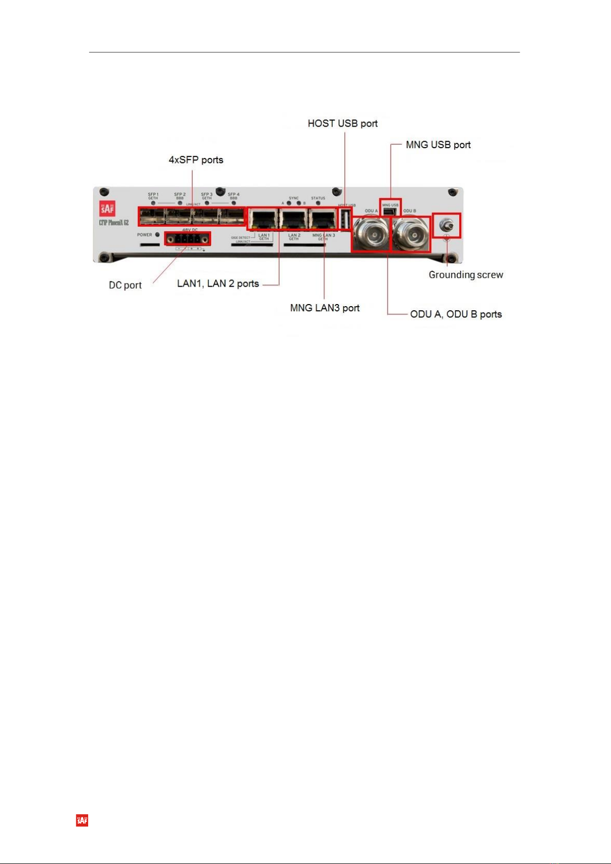
6. Plug the power cable into PhoeniX G2 IDU front panel DC Power connector (DC
port). Place the voltmeter probes on the cable connector screw terminal screw
heads as described in step 2 above. Refer to Figure 10. Note that CFIP
PhoeniX G2 IDU does not have a power on/off switch. When DC power is
connected, the digital radio powers up and is operational. There can be up to
500 mW of RF power present at the antenna port. The antenna should be
directed safely when power is applied.

Phoenix G2 IDU Quick Start Guide
SAF Tehnika JSC 11
7. Turn on the 48 V DC power supply, and verify that the reading on the digital
voltmeter is as specified in step 3 above.
Figure 10: Phoenix G2 IDU DC Power Cable Connector of type 2ESDV-04
After successful powering of PhoeniX G2 IDU there are four ways to adjust and read
settings and operation parameters of the PhoeniX G2 equipment:
Using Web terminal connected to the 10/100/1000Base-T MNG Port,
Using Telnet terminal connected to the 10/100/1000Base-T MNG Port,
Using NMS or SNMP terminal, connected to the 10/100/1000Base-T MNG
Port,
Using Web terminal connected to the USB mini B port.
4.4 Connecting External Multiplexer Modules (EMM) to power
source
The External Multiplexer Module unit (if used) must be connected to the power supply
with a nominal voltage of -48 VDC and GND must be connected to the positive pole.
Connector type 2-pin MC 1,5/ 2-STF-3,81 is supported
4.5 Connecting CFIP Phoenix IRFU to power source
CFIP PhoeniX IRFU (if used) can be powered via coaxial IF cable or using separate
power supply, providing at least 60W load power.
Note that pin 2 (‘+’) of the CFIP PhoeniX IRFU DC Power connector is
connected to the IDU chassis ground internal to the IDU. Use of a power
supply with an inappropriate ground reference may cause damage to CFIP
PhoeniX IRFU and/or the power supply.
4.6 Interconnecting of Phoenix G2 IDU and External
Multiplexer Modules (EMM)
Interconnection of Phoenix G2 IDU and EMM module (if used) must be done using
optical cable and SFP modules. For 1+0 and 2+0 configurations any of all 4 SFP ports
can be used for connection to EMM module. In 1+1 full redundancy configuration SFP

Phoenix G2 IDU Quick Start Guide
SAF Tehnika JSC 12
ports 3 and 4 can be used to connect to EMM module. On EMM module SFP port 1
can be used to connect to Phoenix G2 IDU and SFP port 2 must be used to connect to
the next cascaded EMM module.
Figure 11: Phoenix G2 IDU and EMM module interconnection
4.7 PhoeniX G2 installation in the rack
The PhoeniX G2 IDU is designed in accordance with mounting requirements for
standard 19“ rack cabinet so that it occupies the lowest possible height. The result is
1U height and 1⁄2 width of the standard 19“ rack position. Therefore it is possible to
install two devices alongside each other into one rack slot. Two devices are coupled
by a special “Dual device mount kit” (optional accessory).
Do not forget to ground the PhoeniX G2 Indoor unit using the grounding
screw located on the front panel of the IDU. Use Grounding kit (Grounding
kit is included in the standard device delivery package) for this purpose.
Safety earthing has to be done reliably and solidly.
4.7.1 Single device installation
When installing single IDU in the rack blank panel and bracket must be used. Both are
included in the standard device delivery package.
Figure 12: Single device installation
4.7.2 Dual device installation
Two devices in one slot of 19“ cabinet (2x brackets, 1x Dual device mount kit – use
brackets from each device standard delivery; Dual device mount kit is an optional
accessory)

Phoenix G2 IDU Quick Start Guide
SAF Tehnika JSC 13
Figure 13: Dual device installation
5. Accessing the unit
1. Connect your PC to MNG LAN 3 port on PhoeniX G2 IDU with Ethernet cable.
2. Launch your WEB browser and enter PhoeniX G2 IDU’s IP address in the
address field. Use default IP address 10.10.10.10.
Another management access options are following:
LAN 3 port - IP Address 10.10.10.10, Netmask 255.255.255.0 -
factory default
LAN 3 port - IP Address 192.168.10.10, Netmask 255.255.255.0 -
configurable alternative
MNG USB port - IP Address 10.10.11.10, Netmask 255.255.255.0 -
factory default
MNG USB port - IP Address 192.168.11.10, Netmask 255.255.255.0 -
configurable alternative
Depending on your WEB Browser you may be warned that the device has a
self-signed certificate and thus it is not secure to connect to it. To avoid this
message you have to either setup device certificates or allow an exception
for the target IP. This exception needs to be set up once per each IP
address and WEB browser.
3. Login screen will appear.
4. Enter username and password. Default credentials are as follows:
Username: admin
Password: secret

Phoenix G2 IDU Quick Start Guide
SAF Tehnika JSC 14
Figure 14: Login screen
5. Press button
The WEB GUI interface requires enabled JavaScript in your browser.
There are three access levels available. Default access details for each level
are following:
ACCESS level
LOGIN name
Password
Administrator
admin
secret
User
user
test
Guest
guest
no password
6. Configuration
Short summary about what configuration steps are required for basic 1+0 link:
1) Step 1 –in web GUI “Config System”set Design configuration and modes
(for more details refer to section 6.2 Design and mode settings):
a) Set Design Type to option “Design 505”and press button;
b) Set Duplex Mode to option ”Bidirectional”and press button;
c) Set Functional Mode to option “1+0 Ch1”and press button.
d) Save configuration by pressing button.

Phoenix G2 IDU Quick Start Guide
SAF Tehnika JSC 15
2) Step 2 –in web GUI “Config IP”specify IP address/subnet mask and
Gateway IP of the IDU and press button. For more details refer to
section 6.3 IP address configuration.
3) Step 3 –in web GUI “ConfigSystemDescription”specify Device Name and
press button. For more details refer to section 6.4 Device
name configuration
4) Step 4 –in web GUI “ConfigRadio”set Radio and Modem settings (for more
details refer to section 6.5 Modem and Radio configuration):

Phoenix G2 IDU Quick Start Guide
SAF Tehnika JSC 16
a) Set Bandwidth to required channel bandwidth and press button;
b) Set Max RxACM Profile to required modulation and press button;
c) Set Tx Frequency to required transmitting frequency and press
button;
d) Set Tx Power Limit to required transmitter power level and press
button;
e) Set Tx Mute Config to “auto”and press button;
f) Save configuration by pressing button.
5) Step 5 –in web GUI “ConfigPortsEthVLAN” specify port grouping to
enable required type of management access and port groups. For more details
refer to section 6.6 Management access/channel configuration.
6) Step 6 –Save configuration by pressing button.
6.1 Web GUI description
The WEB GUI is designed as a standalone web application which receives status
updates from the device. This communication is done asynchronously; thus it may
take a while until the change is reflected in the GUI. WEB interface consists of five
parts, those parts are following:

Phoenix G2 IDU Quick Start Guide
SAF Tehnika JSC 17
Figure 15: Phoenix G2 IDU web GUI
1. Web GUI header and status bar - indicates information about link status for
local and remote devices: this section is available while browsing other pages;
2. Two levels menu and Login/Logout box;
3. Third level menu;
4. Side bar frames, contains information about local PhoeniX G2 IDU.
5. Information field.
6.1.1 Refresh Interval
The refresh interval of information shown in the GUI is automatically calculated by the
device depending on actual transmission speed between the WEB browser and the
device. The minimum refresh interval is 2 seconds, the maximal then 30 seconds. The
indication of the next refresh is shown in the Side Bar Information Frame.
6.1.2 Button Convention
There are multiple buttons available across the GUI interface. Buttons have distinctive
colors depending on the effect on the system: pressing the red button may cause
immediate data drop or direct overwriting of start-up parameters in flash memory;
pressing the grey button has not effect; pressing the blue button alters the running
configuration but such configuration needs to be stored by means of the WRITE

Phoenix G2 IDU Quick Start Guide
SAF Tehnika JSC 18
button else it will not persist through the device reboot; and the white button has only
data refreshing option, but such action does not alter the running or stored
configuration. Most common button types used in the WEB GUI are following:
Button
Function
Opens Help/information page
Shown in the status bar when there are
unsaved changes on a connected device
in the link. Using this button, you update
the startup configuration by actually
running configuration on all linked units.
Shown when a value is modified directly
in flash memory but command activation
requires either parameter initialization or
system reboot, for example, IP settings.
Shown when there are pending changes
in the IP settings. By pressing this button,
the device performs a network interfaces
reset. Note, this action does not cause the
user data outage, but it disconnects all
active management sessions (GUI, CLI,
SNMP).
Apply all the changes at current GUI page
or in a respective frame.
Revert all unconfirmed changes in a
respective frame.
Shown only on pages which contain
values which are not automatically
refreshed. It pulls information from the
device and renders it on the screen.
6.1.3 Configuration boxes
The colour of configuration value entered in a setting box indicates the status of the
following value:
black –unmodified value
blue –modified but non-applied value

Phoenix G2 IDU Quick Start Guide
SAF Tehnika JSC 19
red –entered value does not match the allowed range
purple –the actual configuration does not match the required modem
settings.
Setting input boxes may change its border colour to red if the entered value is not
applicable, for example, invalid IP address or a character in an integer-type field. In
such event, the button is hidden until the problem is fixed.
6.1.4 Header and Status bar
The header displays the actual link condition. The RF path diagram varies depending
on the used Design and Mode setting. In the Split 511 design, the actual Local Primary
unit is displayed in the first header row, the Local Secondary on the second row. Bold
font highlights the actually managed unit. The physically linked RF units are always in
the same row. The displayed speed is average maximal throughput per last second.
Meaning of the used graphics is described in the following picture:
Figure 16: Phoenix G2 IDU web GUI header and status bar

Phoenix G2 IDU Quick Start Guide
SAF Tehnika JSC 20
6.1.5 Main menu
The main menu located on the left side allows user navigation among all major
sections of the GUI. The administrative role of the current login and the logout button
is displayed above the main menu. The user can expand the menu tree structure
either by using the arrows on the left or using double-click on the desired section. The
menu tree structure is sorted in the following manner to allow successive
configuration and monitoring:
Status –Informational section designed for link performance monitoring.
Config –Configuration section. The user can perform configuration of all
necessary parameters from top to bottom as some options may override
consecutive settings, for example, the Design and Mode change invokes a
preset load and changes page layout of the Ports section. It is highly
recommended to save and reboot the device once the first complete
configuration is done.
Maintenance –A device management section which houses tools for device
configuration backups, FW/License upgrade, log files and troubleshooting
sections, and reboot.
Tools –Set of various tools for advanced debugging tasks such as Ping,
Terminal, Constellation and Spectrum analysis.
6.1.6 Side bar information frame
The Side Bar located on the left side of the GUI shows the summary of important
device information:
Date –system date
Time –system time
Uptime –time since startup
Refresh status –indicates the amount of time until the next GUI refresh. The
bar changes its colour to red if the GUI auto-refresh is frozen through the
button
Modem Serial Number –device Serial Number. It is shown only when it differs
from the License Number
License Number –the license number
License Type / Status –shows if the license is permanent or time-limited and
its status
License Expiration –shows the remaining time until the license expires.
Firmware Version –version of the device firmware.
Running Design –active design type.
Other manuals for Phoenix G2 IDU
1
Table of contents
Other SAF Network Hardware manuals
Popular Network Hardware manuals by other brands

KEMP Technologies
KEMP Technologies LoadMaster 1500 Installation and configuration guide

ADC
ADC HiGain H2TU-C-231 Quick installation

ADC
ADC HIGAIN H4TU-C-388 Quick installation

Intellinet
Intellinet 524179 user manual

Seenergy
Seenergy SVR-104 Quick installation guide

Jinan USR IOT Technology
Jinan USR IOT Technology USR-TCP232-T instructions

Eci Telecom
Eci Telecom ONT B-FOCuS O-4F2PW Hardware installation manual

Centrica
Centrica Panoramic Power Installation and configuration guide

Lucent Technologies
Lucent Technologies WaveStar OLS 40G installation manual

KonNad
KonNad C2000-A2-KDDA0A0-AD6 user manual

LaView
LaView LV-N9808C8E user manual

NetComm
NetComm CC100 user guide