7
Installation and Operation Manual
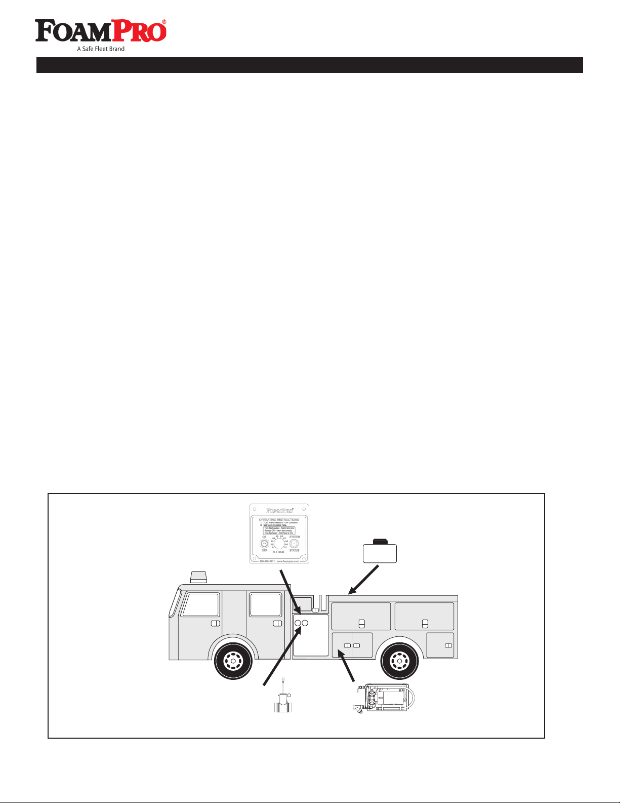
System 1600/1601
The FoamPro 1600/1601 system is provided with the major components and accessories required for installation.
Due to differences in chassis and apparatus configurations, the installer must provide pipe, hoses, tubing, wire
and fittings to satisfy installation requirements. The following paragraphs list the specifications for selection of
these components. Before beginning system installation, read this section thoroughly to make sure the proper
components are selected. For detailed system installation instructions, refer to Sections 5, 6 and 7.
FOAM CONCENTRATE SUCTION LINE
Corrosion-resistant fittings and hoses from the foam tank to
the inlet of the foam pump must be used. Use 3/4 inch [19
mm] minimum inside diameter or larger hose dependent
on the viscosity of the foam concentrate. Use components
that are rated for 23 in [584.2 mm] Hg vacuum and 50 psi
[3 BAR] pressure or greater. The components must be
compatible with all foam concentrates to be used. Fittings
used must be made of brass, 300 series stainless steel or
other corrosion resistant material. Before selection of hose
fittings, check for compatibility with foam concentrates to
be used. The use of clear suction hose is recommended
to allow viewing foam priming operations. The foam pump
must be positioned to allow no more than a 3 foot lift to a
positive suction head from the foam tank. A net positive
suction head (NPSH) is recommended.
FOAM CONCENTRATE DISCHARGE LINE
Fittings and hoses from the discharge of the foam pump
to the injector fitting must be supplied by the installer.
Hoses and fittings of 3/8-inch [9.5 mm] minimum INSIDE
diameter, rated at 400 psi [28 BAR] minimum working
pressure or maximum discharge pressure of the fire pump,
whichever is greater, must be supplied by the installer.
Fittings and hoses must be compatible with all foam
concentrates to be used. Use fittings of brass, 300 series
stainless steel or other corrosion resistant material that is
compatible with all foam concentrates to be used.
CHECK VALVES
NFPA requires installation of a check valve in the foam
concentrate injection line. To prevent foam concentrate
flow from the tank due to static head pressure, the foam
concentrate check valve shall have a 12 psi [0.6 BAR]
cracking pressure and shall be capable of withstanding the
pressures that will be generated in the foam injection line.
A check valve is also required in all water piping locations
where foam concentrate could drain back into pumps or
other components of the fire apparatus. As a minimum,
one check valve must be installed where the foam
solution water piping connects to the fire pump discharge
(FoamPro Main Waterway Check Valve is recommended).
Multiple drains that allow individual drain lines to
communicate may allow foam to short circuit past
the check valves; avoid this possibility. FoamPro
recommends separate drain valve(s) for the
discharge piping.
FOAM CONCENTRATE TANK
A foam concentrate tank must be supplied to
suit the capacity required for the apparatus
application. The tank should meet NFPA minimum
standards for the design capacity, including filler size,
venting and drain facility. A shut-off valve is recommended
to allow cleaning of the strainer.
ELECTRICAL REQUIREMENTS
Electrical wiring must be supplied from the main apparatus
electrical system to the foam pump base system. Power
must be supplied directly from the apparatus battery
without any connections to other high power devices, such
as primer pumps, hose reels, auxiliary starters, light bars,
etc. with its own disconnect switch, or a switch or contactor
actuated by the battery disconnect switch, PTO or other
device. Use proper wire size to be able to supply the foam
system with the proper voltage and amperage required.
The minimum service is as follows:
1600/1601 12VDC requires 32 amps
1600/1601 24VDC requires 16 amps
Braided flat ground straps are required for ground
connections. The flat straps limit the RFI/EMI interference
encountered with radios, computers or other sensitive
electronic equipment.
CAUTION: Always disconnect the ground straps
and control cables from the control module or
other FoamPro equipment before electric arc
welding at any point on the apparatus. Failure to
do so will result in a power surge through the
unit that could cause irreparable damage to the
electronic components.
4 Installer Supplied Parts