Safety Technology International STI-1229HTR-HAZ User manual

Features:
• Hazardous Classification Class II roups F& Div. 2 and Class III locations.
• Maintains operating strobe appliance temperature with external
temperatures to -70°F (-57°C).
• Enclosure tested to NEMA 4X Standards. Equivalent to an IP 66 rating.
• UL/cUL Listed.
• CSFM requires local approval only.
• Protects ADA compliant strobes to UL 1971 Standards.
Operation:
For use in areas where temperature or environmental conditions exceed the
operating range of fire strobe signaling devices. Unit requires 24 VDC
continuous for fan operation and 110 VAC or 240 VAC for heater, as well as
power for strobe operation and supervision for temperature indicator. Fan
runs continuously to maintain uniform temperature. Heater cycles as
required to maintain operating temperature range for listed strobes.
STI-1229-HAZ Enclosure only
STI-1229HTR-HAZ Enclosure with 110 VAC Heater Option
STI-1229HTR240-HAZ Enclosure with 240 VAC Heater Option
We protect the things that protect you.

2
arnings
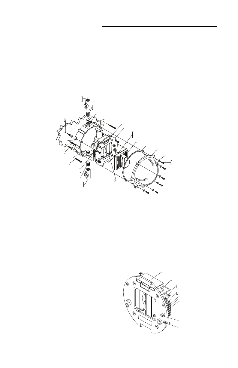
The enclosure is used to protect UL/cUL listed 1638 and 1971 visual
notification appliances at temperatures down to -70˚F (-57˚C). It is the
installer’s responsibility to comply with NEC 70 Articles 502 and 503, NFPA72,
and other applicable fire and electrical codes. Conduit or raceway paths need
to be sealed as near to the enclosure as possible. Installer should have
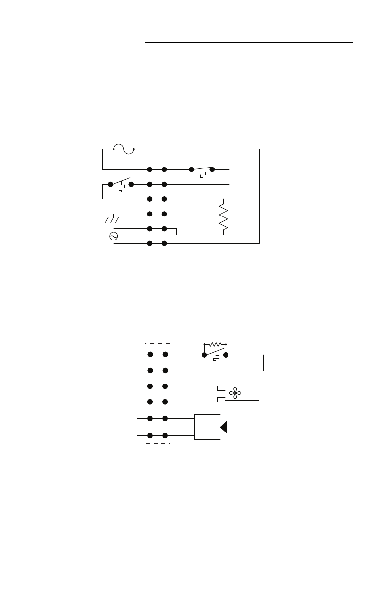
maintained supervision over the low temperature thermostat. The low
temperature monitoring thermostat makes the circuit at +32°F (0°C) and
clears the circuit at +50°F (+10°C). This listing requires that the fire alarm
supervisory control module be only of the latching type. On the appliance
mounting plate is a label where you should record the installation date. Also
include below the serial number and installation date on the instruction sheet
for quick reference.
Serial Number ____________________________________
Installation Date __________________________________
!
Installation Notes
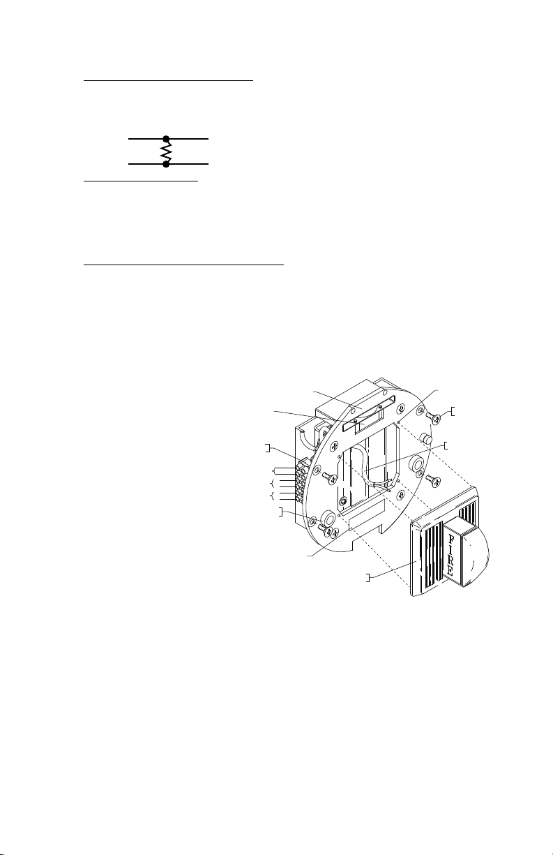
1. The enclosure is rated to protect signaling appliances indoors and
outdoors and in areas of direct weather exposure.
2. When covering fire-signaling appliances with the enclosure, some light
loss occurs. Please follow the guidelines listed during installation.
3. Strobe light loss values for respective manufacturers are shown on page
3. To determine the new composite candela value of the use with the
guard refer to the sample calculation shown on page 3 for a
manufacturer’s strobe.
4. Record the manufacturer’s candela value as “A” and the light loss value
as “B” and the assembly value as “C”. Example: A 60 candela strobe with
a 30% light loss transmission value. Value “A” is now 60. Value “B” is
(60 times 30% or 0.30) in this case 18.
5. Now value “C” is value “A” minus value “B” or 60-18 = 42 candela light
source. Now refer to NFPA tables for proper room size that newly
established value “C” will work in. Then submittal installation drawings
must show the composite candela value in this example 42.
6. On a multiple candela value strobe such as 15/30/75 a calculation must
be done for each value and the drawing notation composite value for
each number on the strobe.
7. All field wiring within this enclosure must be rated for a minimum
operating range of 0ºC - 110ºC.

3
Performance Review
Manufacturer Category/Model Light Loss
American Security Equip. Co. Select-a-strobe SL24W-153075 36% Light Loss
Faraday 2700 33% Light Loss
entex See note below* 36% Light Loss
System Sensor SS24110ADA 35% Light Loss
Polycarbonate Cleaning Instructions
Rinse with water to remove abrasive dust and dirt. Wash with soap or mild
detergent, using a soft cloth. Rinse once more, then dry with a soft cloth or
chamois. Exercise caution when using water inside enclosure. Make sure unit
is completely dry inside before reassembling. (Do not use razor blades).
Specifications
Fan:
24 VDC, 90 mA UL Recognized Component
Life: 5 Years Continuous Duty
WARNIN : The polarity of the circulating fan is important as it only
rotates in one direction with red lead being positive.
Gasket:
Material: Neoprene
Life: 5 Years
!
*NOTE FOR GENTEX: ES24 may be followed by W, R or P.
Silicone Laminate Heater:
STI-1229HTR-HAZ 110 VAC 50/60 Hz UL Recognized Component
STI-1229HTR240-HAZ 240 VAC 50/60 Hz UL Recognized Component
100 Watts
Life: @ -10˚C (14˚F) ~ 70˚C (158˚F) 5 Years
Duty Cycle: -40˚F (-40˚C) 53%
-70˚F (-57˚C) 71%
Polycarbonate Enclosure:
Flammability: UL94 V-2
Wall Thickness: 0.2 in (5.1mm)
NEMA Rating: 4X, indoor and outdoor use
Hazardous Rating: Class II roups F& Div. 2
and Class III locations
Warranty: Three year guarantee against breakage of
polycarbonate in normal use (one year on electro
mechanical and electronic components).

4
Installation Instructions
MOUN BACKBOX O WALL (Refer to Fig. 1)
1. Remove appliance heater assembly from back box and set aside.
2. Mount back box in desired location (wall mount only) using the four #10
x 1-1/2” screws and anchors (provided). Drill a 1/4” diameter pilot hole
for plastic anchors at spacing in Fig. 1.
3. Attach conduit hub to a 3/4” NPT nipple and conduit seal fitting to the back
box, top and bottom.
Note: A conduit seal fitting must be used on both top and bottom
conduit entries as close to the unit as possible. Use conduit seal Crouse-
Hinds 3/4” EYSX 21 or equivalent. Conduit should be installed according
to applicable NEC and local codes.
4. Pull wiring into back box.
Note: High Voltage (110 or 240 VAC) wiring must enter thru bottom
conduit and low voltage and signaling wires must enter thru top conduit
and remain separated per NFPA
70, NEC, and local codes.
HIGH VOL AGE WIRING (Refer to Fig. 2)
5. Connect high voltage: Make sure
110 or 240 VAC power is “OFF”.
Refer to high voltage schematic
diagram on page 6.
110 VAC 240 VAC
Pin 6 AC HOT L-1
Pin 5 Neutral L-2
Pin 4 round round
3/4 in.(25mm)NPTNIPPLE
(NOTPROVIDED)
ENCLOSEDBACKBOX
HEATERASSEMBLY
HIGH VOLTAGETERMINAL BLOCK
SCREW#8-32 x 3/8 in.
(4) PROVIDED
STROBE APPLIANCE
GASKET(1) PROVIDED
SOLID CLEARCOVER
WASHER(6) PROVIDED
#8-32 x 3/4 in.SOCKET
CAP SCREW(6) PROVIDED
LOWVOLTAGE
ELECTRICAL ENTRY
1/4 in.(6.3mm)
DIA.HOLE
ANCHOR
(4) PROVIDED
SCREW#10 x 1 1/2 in.
(4) PROVIDED
LOWVOLTAGE TERMINAL BLOCK
3/4 in.NPT.NIPPLE
(NOTPROVIDED)
HIGHVOLTAGE
ELECTRICAL ENTRY
APPLIANCE
WIRE
3/4 in.NPT HUB (2) PROVIDED(WITHOUTHEATER(1) PROVIDED)
FIGURE 3
1
(6.4
HEATER ASSEMBLY
HEATER
OVERTEMP SAFETY
THERMOSTAT
HIGH VOLTAGE
TERMINAL BLOCK
PIN 6
PIN 5
PIN 4
2 A FUSE
CONTROL THERMOSTAT
F
1
2
3
4
5
6
1
2
FIGURE 1
FIGURE 2

5
LOW VOL AGE WIRING (Refer to Fig. 3 & Schematic drawings on Page 6)
6. Connect Supervisory Module Connect EOL device (not included) between
pins 1 and 2 of low voltage terminal block. Pins 1 and 2 should then be
connected to the fire alarm supervisory control module.
Note: Fire alarm supervisory control module must be of the latching type only.
Pin 1 Alarm Supervisory
Pin 2 Control Module
7. Connect Fan Power
Note: Fan will not operate if polarity is reversed. Refer to low voltage
schematic on page 6.
Pin 3 -24 VDC
Pin 4 +24 VDC
8. Connect strobe appliance power
Pin 5 - 16-33 VDC
Pin 6 +16-33 VDC
9. Attach heater assembly to back box using (4) #8-32 x 3/8” flat head
screws into heater assembly mounting bosses on back box (see Fig. 1).
Make sure all service wiring is gathered away from the heater and be
careful not to pinch wire under heater assembly. Fan must be mounted
toward top of
enclosure.
10. Wire strobe using
Teflon coated wire
provided. (White-
P o s i t i v e / B l a c k-
Negative) and
attach to the strobe
mounting bosses on
heater assembly.
11. Record installation
date on label and in
manual (page 2).
12. Install cover and
gasket with (6) #8-
32 x 3/4” socket cap screws and (6) flat washers as shown in Fig. 4.
13. Turn all power to “ON” position.
Note: Fan runs continuously. This system requires three sources of power:
1. 110 or 240 VAC heater on the load side of the fuse holder.
2. 24 VDC power source for the circulating fan. Check fan to see if
operating; if not check polarity and reverse then try again
3. 16-33 VDC fire alarm notification circuit for strobes and temperature
warning monitor.
EOL
DEVICE
HEATER ASSEMBLY
FAN
LOW VOLTAGE
TERMINAL BLOCK
LOW TEMP
WARNING
FAN POWER
STROBE
POWER
LOW TEMP WARNING
THERMOSTAT
STROBE
(NOT PROVIDED)
STROBE HOOK-UP
WIRE
HEATER ASSEMBLY
MOUNTING SCREW
STROBE MOUNTING BOSS
1
2
3
4
5
6
-
+
+
-
1
2
WARNING LABEL
FIGURE 3

6
Schematic Diagrams
2AMP FUSE
OVERTEMP SAFETY
1
2
4
3
5
6
CONTROL
110 OR 240 VAC
SINGLE PHASE
4
5
3
6
1
2
STROBE
PWR
FAN
PWR
TEMP
WARNING
SUPERVISOR
_
+
+
_
FAN
LOW TEMP WARNING
STROBE (16-33VDC 600mA)
S
LOW VOLTAGE CIRCUIT
HIGH VOLTAGE CIRCUIT
TERMINAL
BLOCK
TERMINAL
BLOCK
CHASSIS
HEATER
EOL DEVICE
SUPPLIED BY
CUSTOMER
OPEN @ 70˚F
CLOSE @ 50˚F
OPEN @ 120˚F
CLOSE @ 80˚F
OPEN @ 50˚F
CLOSE @ 32˚F
(24VDC 90mA)
110 OR 240 VAC 50/60 Hz
100 WATTS
2

7
9.37 in.(238mm)
PRODUCT DIMENSIONS
2.87 in.(73mm)
APPLIANCE MOUNTING
BACKPLATE
5.5 in.
(140mm)
7.25 in.(184mm)
Product Assembly
SEALING HUB
(NOT PROVIDED)
3/4 in.(25mm) NPT NIPPLE
(NOT PROVIDED)
ENCLOSED BACKBOX
HEATER ASSEMBLY
FAN
HIGH VOLTAGE TERMINAL BLOCK
FUSE
CONTROL THERMOSTAT
SCREW #8-32 x3/8 in.
(4) PROVIDED
STROBE APPLIANCE
GASKET(1) PROVIDED
SOLID CLEARCOVER
WASHER (6) PROVIDED
#8-32x3/4 in. SOCKET
CAP SCREW (6)PROVIDED
LOW VOLTAGE
ELECTRICAL ENTRY
IN AREAS WHERE FREQUENT
WASH DOWNS OCCUR
WASHERS MAY BE USED TO
STAND OFF ENCLOSED SPACER
(NOT PROVIDED)
1/4 in. (6.3mm)
DIA. HOLE
ANCHOR
(4)PROVIDED
SCREW #10x 1 1/2in.
(4) PROVIDED
LOW VOLTAGE TERMINAL BLOCK
3/4 in.NPT.NIPPLE
(NOTPROVIDED)
HIGHVOLTAGE
ELECTRICAL ENTRY
WARNINGLABEL
SEALINGHUB
(NOTPROVIDED)
APPLIANCE
WIRE
3/4 in. NPT HUB (2) PROVIDED (WITHOUT HEATER (1) PROVIDED)
LOW TEMP
WARNING
THERMOSTAT
FIGURE 4

Printed in USA SUBJECT TO CHAN E WITHOUT NOTICE Inst. Sht. 1229HTR-HAZ IS SEPT2009
Safety Technology International, Inc.
2306 Airport Road
aterford, Michigan 48327-1209
Phone: 248-673-9898 • Toll Free: 800-888-4784 • Fax: 248-673-1246
Safety Technology International (Europe) Ltd.
Unit 49G Pipers Road • Park Farm Industrial Estate • Redditch
orcestershire • B98 0HU • England • Tel: 44 (0) 1527 520 999
Fax: 44 (0) 1527 501 999 • Freephone: 0800 085 1678 (UK only)
E-mail: [email protected] • eb: www.sti-europe.com
www.sti-usa.com
Warranty
Three year guarantee against breakage of polycarbonate in normal use
(one year on electro mechanical and electronic components).
Electronic warranty form at www.sti-usa.com/wc14.
This manual suits for next models
2
Table of contents