SERVICE / MAINTENANCE
The 711 Series Control requires regular
maintenance to ensure continue , safe oper-
ation. During normal boiler function, se i-
ment may accumulate in the low water cut-
off's probe housing. If left unchecke , this
se iment can buil up, trap water in the
probe housing, an prevent the control from
etecting a low water con ition in the boiler.
A regular blow own of the control is
require for proper operation.
To flush the se iment from the chamber, the
control must be blown own throughout the
heating season in accor ance with the fol-
lowing sche ule:
• Daily for first week following control
installation
• Prior to heating season startup in the fall
• Once per week uring the heating season
I structio s: Confirm water is visible in the
gauge glass. If not visible, shut the burner
off, allow the boiler to fully cool, then a
water until visible in the gauge glass. Once
water is visible, bring your boiler back up to
temperature. With the boiler running, place a
heat resistant pail irectly beneath the con-
trol casting blow own valve. Open the valve
an allow the se iment an water to rain
into the pail. Continue to rain the water
until it runs clean (One to two gallons is gen-
erally sufficient). Close the valve when com-
plete . Replenish the water in the boiler if
nee e .
OPERATING INSTRUCTIONS
TROUBLESHOOTING
1If the burner oes not shut own upon
water falling below the lower probe:
Remove power to the burner an check
installation. Check wiring an make sure
that burner is connecte to the fourth ter-
minal from left on terminal (P2). If wiring
is correct, check to make sure the probes
are not falsely groun e . Voltage between
the probes an chassis groun shoul be
120-140 VAC with water beneath both
probes. A lower rea ing may in icate a
shorte probe. Remove probes an check
for contamination.
2If the burner will not fire with water at the
top probe: With a voltmeter an power
applie at terminals G an H: Check the
voltage between the upper probe an
chassis groun . Rea ing shoul be 0-10
VAC with water at the upper probe. A
higher rea ing may be the result of poorly
con uctive water or probe contamination.
Remove probes an check for contamina-
tion. If the burner will still not fire after
cleaning probes, contact factory for assis-
tance.
5
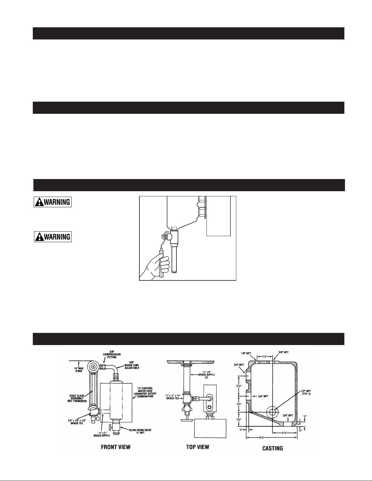
DIMENSIONS
NOTE: Hy rolevel recommen s that the boil-
er manufacturer’s proce ures for skimming
the boiler be performe prior to placing the
control into operation.
1After installation, raise the boiler water
level until water is in contact with the
upper probe. Turn on power an set the
thermostat to call for heat. The burner
shoul fire imme iately.
2Using the boiler rain, slowly lower the
water level to a point below the lower
probe. The burner shoul shut own
imme iately upon a low water con ition.
NOTE: The water shoul not be lowere
beyon a visible point on the gauge glass.
IMPORTANT: If the burner oes not shut
own in a low water con ition, turn off
power imme iately an refer to trou-
bleshooting instructions below.
REGULAR MAINTENANCE
REQUIRED. Failure to
properly maintain the control can lea to
severe amage to the boiler, other property,
personal injury, or eath.
To prevent serious person-
al injury from steam an
hot water, make sure there is a ischarge line
from the blow own valve to a proper place of
isposal. Failure to follow this caution coul
result in personal injury.