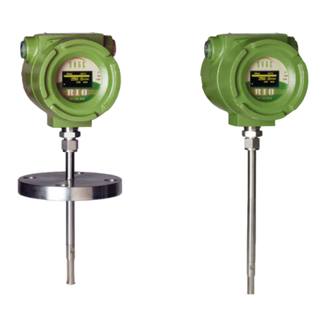
Sage SIE Series Guide

SAGE THERMAL GAS MASS LOW METER
Operations and
Instruction Manual
or Explosion Proof Style Models SIE and SRE
DOCUMENT NUMBER 100-0066
REVISION 03 - SIE/SRE (EXPLOSION PROO )
Make the Wise Choice.
Choose Sage low Meters.
SAGE METERING, INC.
8 Harris Court, D1
Monterey, CA 93940
1-866-677-SAGE (7243)
Tel 831-242-2030
Fax 831-655-4965
www.sagemetering.com


3
S A G E M E T E R I N G , I N C .
O p e r a t i o n s a n d I n s t r u c t i o n M a n u a l
Table of Contents
REV. 03-SIE/SRE
Introduction Welcome . . . . . . . . . . . . . . . . . . . . . . . . . . . . . . . . . . . . . . . . . . . . . . . . . . . . . . . 5
SECTION A Unpacking Your Sage Meter . . . . . . . . . . . . . . . . . . . . . . . . . . . . . . . . . . . . . . . . 9
Getting Started Maintenance . . . . . . . . . . . . . . . . . . . . . . . . . . . . . . . . . . . . . . . . . . . . . . . . . . . 9
Calibration . . . . . . . . . . . . . . . . . . . . . . . . . . . . . . . . . . . . . . . . . . . . . . . . . . . . . 9
Installation and Mounting . . . . . . . . . . . . . . . . . . . . . . . . . . . . . . . . . . . . . . . . . 10
Locating Proper Wiring Diagram . . . . . . . . . . . . . . . . . . . . . . . . . . . . . . . . . . . . 10
Wiring of the Series SIE/SRE . . . . . . . . . . . . . . . . . . . . . . . . . . . . . . . . . . . . . . . . 10
Self-Powered 4-20mA or User Powered 4-20mA. . . . . . . . . . . . . . . . . . . . . . . . . 11
Insertion Flow Meter Application. . . . . . . . . . . . . . . . . . . . . . . . . . . . . . . . . . . . 11
In-line Flow Meter Application . . . . . . . . . . . . . . . . . . . . . . . . . . . . . . . . . . . . . 11
Flow Conditioning . . . . . . . . . . . . . . . . . . . . . . . . . . . . . . . . . . . . . . . . . . . . . . . 12
Compression Fitting . . . . . . . . . . . . . . . . . . . . . . . . . . . . . . . . . . . . . . . . . . . . . . 13
Installation Instructions . . . . . . . . . . . . . . . . . . . . . . . . . . . . . . . . . . . . . . . . . . . 13
Probe Insertion Guideline Drawing . . . . . . . . . . . . . . . . . . . . . . . . . . . . . . . . . . 14
Installation Depth Chart . . . . . . . . . . . . . . . . . . . . . . . . . . . . . . . . . . . . . . . . . . 15
Configuration for Utilizing Four Flow Meters for Large Round Pipes. . . . . . . . 16
Terminal Hook-Up Series SIE, SRE . . . . . . . . . . . . . . . . . . . . . . . . . . . . . . . . . . . 17
Cable Connector Diagram for AC Powered
Explosion-Proof Meters (SIE or SRE) . . . . . . . . . . . . . . . . . . . . . . . . . . . . . . . 18
Junction Box Wiring Terminals for Remote Style Meters . . . . . . . . . . . . . . . . . 19
Circuit Board Wiring for Explosion Proof Style Meter. . . . . . . . . . . . . . . . . . . . 20
RS232 Cable Connector Assembly . . . . . . . . . . . . . . . . . . . . . . . . . . . . . . . . . . . 21
Sage Remote Mounting Hardware . . . . . . . . . . . . . . . . . . . . . . . . . . . . . . . . . . . 22
SECTION B Styles and Features . . . . . . . . . . . . . . . . . . . . . . . . . . . . . . . . . . . . . . . . . . . . . . . 25
Theory / Styles / Specifications Principle of Operation . . . . . . . . . . . . . . . . . . . . . . . . . . . . . . . . . . . . . . . . . . . . 27
Basic Heavy Industrial Sage Flow Meter Styles. . . . . . . . . . . . . . . . . . . . . . . . . . 27
SECTION C SIE Series Integral Style General Purpose Mass Flow Meters. . . . . . . . . . . . . . 31
Drawing SRE Series Remote Style General Purpose Mass Flow Meters. . . . . . . . . . . . . . . 32
Remote Bracket Layout . . . . . . . . . . . . . . . . . . . . . . . . . . . . . . . . . . . . . . . . . . . . 33
Mounting Hardware:
SVA Series Isolation Valve Assembly for Insertion Meters . . . . . . . . . . . . . . 34
SVA Series Isolation Valve Assembly Detail . . . . . . . . . . . . . . . . . . . . . . . . . . 34
STCF Series Teflon Ferrule Compression Fitting . . . . . . . . . . . . . . . . . . . . . . 34
Mounting Plate for Thin Walled Ducts . . . . . . . . . . . . . . . . . . . . . . . . . . . . . 34
SVA05 LP Low Pressure Isolation Valve Assembly. . . . . . . . . . . . . . . . . . . . . 35
Optional Flanges (For In-Line and Insertion Flow Meters) . . . . . . . . . . . . . . . . 36
In-Line Flow Conditioning Screens . . . . . . . . . . . . . . . . . . . . . . . . . . . . . . . . . . 37
Optional Flow Conditioners (for Insertion Flow Meter applications). . . . . . . . 38
cont nued on next page

S A G E M E T E R I N G , I N C . O p e r a t i o n s a n d I n s t r u c t i o n M a n u a l
4
REV. 03-SIE/SRE
SECTION D User Interface – Menus . . . . . . . . . . . . . . . . . . . . . . . . . . . . . . . . . . . . . . . . . . . . 41
User Interface Sensor Functionality and Zero Calibration Self Check . . . . . . . . . . . . . . . . . . . 42
Simplified Keypad Instructions. . . . . . . . . . . . . . . . . . . . . . . . . . . . . . . . . . . . . . 44
VIP Menus and Items . . . . . . . . . . . . . . . . . . . . . . . . . . . . . . . . . . . . . . . . . . . . . 45
Menu Item Descriptions . . . . . . . . . . . . . . . . . . . . . . . . . . . . . . . . . . . . . . . . . . . 47
Detailed Keypad Navigation and Menus . . . . . . . . . . . . . . . . . . . . . . . . . . . . . . 49
Pulsed Outputs, Alarms, Relays and Timer Settings. . . . . . . . . . . . . . . . . . . . . . 50
Wiring for Pulsed Output . . . . . . . . . . . . . . . . . . . . . . . . . . . . . . . . . . . . . . . . . . 51
Common Examples Using the Keypad. . . . . . . . . . . . . . . . . . . . . . . . . . . . . . . . 52
Range Changing Shortcut. . . . . . . . . . . . . . . . . . . . . . . . . . . . . . . . . . . . . . . . . . 56
Examples Using the Laptop . . . . . . . . . . . . . . . . . . . . . . . . . . . . . . . . . . . . . . . . 57
SECTION E Common Diagnostics . . . . . . . . . . . . . . . . . . . . . . . . . . . . . . . . . . . . . . . . . . . . . 61
Diagnostics
SECTION F Limited Warranty . . . . . . . . . . . . . . . . . . . . . . . . . . . . . . . . . . . . . . . . . . . . . . . . 65
Warranties and Service Work Cancellation/Return Policy. . . . . . . . . . . . . . . . . . . . . . . . . . . . . . . . . . . . . . . . . 65
Returning Your Sage Flow Meter . . . . . . . . . . . . . . . . . . . . . . . . . . . . . . . . . . . . 67
Return Material Authorization Form . . . . . . . . . . . . . . . . . . . . . . . . . . . . . . . . . 68
SECTION G Character Locations . . . . . . . . . . . . . . . . . . . . . . . . . . . . . . . . . . . . . . . . . . . . . . 71
Appendix Junction Box and Upstream Orientation . . . . . . . . . . . . . . . . . . . . . . . . . . . . . . 72
Installations Where Pipe Condensation May Develop . . . . . . . . . . . . . . . . . . . 73
VIP Screen Shot . . . . . . . . . . . . . . . . . . . . . . . . . . . . . . . . . . . . . . . . . . . . . . . . . . 74
What Is a Thermal Mass Flow Meter? . . . . . . . . . . . . . . . . . . . . . . . . . . . . . . . . 75

O p e r a t i o n s a n d I n s t r u c t i o n M a n u a l 5
Welcome
S A G E M E T E R I N G , I N C .
REV. 03-SIE/SRE
We are pleased that you have purchased a Sage Metering Mass Flow Meter for your
requirement. We hope that you are satisfied with the performance, operation and
design of our highly precise, NIST traceable Thermal Gas Mass Flow Meter.
Sage Metering is your source for monitoring, measuring and controlling the gas mass
flow in your industrial process, building management system or environmental appli -
cation. Our high performance, NIST Traceable,Thermal Mass Flow Meters will help
increase productivity, reduce energy costs, maximize product yields, and/ or help reduce
environmental insult. Sage provides high quality In-Line and Insertion Thermal Mass
Flow Meters for a wide variety of industrial, commercial, and environmental monitoring
needs, including carbon credit verification for Greenhouse Gas reduction.
Sage Meters measure mass flow directly — there is no need for ancillary instrumentation
such as temperature or pressure transmitters. Furthermore, our instruments have excep-
tional signal sensitivity, have no moving parts, require little if any maintenance, have
negligible pressure drop and have a turndown up to 100 to 1, and resolve as much as
1000 to 1. Sage Flow Meters can measure and control the mass flow rate and consump-
tion of air, oxygen, natural gas, nitrogen, digester gas, biogas, flare gas, hydrogen, argon,
carbon dioxide and other gases and gas mixes.
The innovative Sage design (whether configured as an In-Line or Insertion Flow Meter)
provides high accuracy and repeatability for optimum measurement and control of
your process and offers a large-format back-lit display of mass flow, total and temper -
ature. Isolated 4-20mA outputs of flow and temperature are standard. In addition,
pulsed outputs of consumption are available off of the Relay contacts. Furthermore,
the Sage Meter includes a user-friendly Touch Display Screen keypad and powerful
menuing system to integrate the functions of flow measurement with your specific
needs. For even greater flexibility, multiple channels (up to four calibrations) are
available in one meter.
Please let us know if we can assist you in any way with your Sage Meter, or if you
have any questions about its installation, operation, or features. Simply phone us at
866-677-SAGE (7243), or visit our website at www.sagemetering.com to contact a
factory representative in your area. (To access this manual on the website, enter in the
user name “sage” followed by the passcode “7243737” when prompted.)
Sincerely,
Robert Steinberg
Pres dent


Section
GETTING STARTED
A


O p e r a t i o n s a n d I n s t r u c t i o n M a n u a l
UNPACKING YOUR SAGE METER
Your Sage flow meter is a sensitive, yet rugged,
precision built electronic instrument. Upon delivery,
care should be taken when opening the shipping
container and removing your meter. The meter
should be inspected for any damage that may have
occurred during transit. If damage is found, please
contact the carrier immediately to place a claim for
damaged goods. The contents of the container
should be checked against the packing list for any
discrepancies. If there are any questions as to the
contents or configuration of the equipment includ-
ing calibration ranges, or, mounting hardware,
contact Sage Metering as soon as possible. Please
save shipping container and packaging materials
(including PVC tube probe protector on Sage
Insertion Flow Meters) in case the unit needs to
be returned for any reason.
MAINTENANCE
Sage thermal mass flow meters essentially require
little or no maintenance. While the sensing element
is somewhat resistant to dirt and particulate build
up, it may become necessary to clean it from time to
time if mounted in extremely dirty environments.
NOTE: ALWAYS DISABLE THE TRANSMITTER
POWER SUPPLY PRIOR TO ANY CLEANING OR
MAINTENANCE. A detergent or appropriate
non-corrosive solvent for removing the buildup
may be required. A soft brush can be used to gently
clean the sensing element’s surface, using caution
to avoid damaging the sensor elements (the RTDs).
If any disassembly is necessary, contact Sage
Metering, Inc. for instructions. In general, it is
recommended that your Sage Thermal Mass Flow
Meter be returned to the factory if cleaning,
repair, or recalibration is needed. This is usually
the most cost-effective and reliable alternative.
CALIBRATION
Sage thermal mass flow meters have built-in diag -
nostics. The menuing system (see Section D) has
provisions to check the sensor’s operation by ac cess -
ing the sensor’s output and comparing it to the origi -
nal reported “zero flow” value noted on the last few
lines of your meter’s Certificate of Conformance.
This diagnostic procedure not only checks the sensor
performance and the "live zero" calibration point,
but it verifies that the sensor is clean. It essentially
provides a means to validate the meter's perform-
ance, verifies that there is no shift or drift, and elimi-
nates the need for annual factory calibrations. See
“Sensor Functionality and Zero Calibration Self
Check” on page 42.
Getting Started
9
S A G E M E T E R I N G , I N C .
REV. 03-SIE/SRE
aCAUTION Cable glands shipped with unit are for shipping purposes only.
Remove shipping cable glands before installing.
aCAUTION If installing in a Class I hazardous location the installation
must comply with appropriate electrical codes (CSA units per CEC Part 1
Appendix J18-100).
aCAUTION Installer must supply proper ground and bond wire for the
transmitter and the sensor per appropriate electrical codes (CSA units per
CEC Part 1).

S A G E M E T E R I N G , I N C . O p e r a t i o n s a n d I n s t r u c t i o n M a n u a l
10
INSTALLATION AND MOUNTING
■Check the Certificate of Conformance included
with your Sage Thermal Mass Flow Meter for
system pressure, temperature, gas composition,
power input, and signal output.
■It is recommended that the flow meter be inserted
in a location of maximum straight run. It is sug-
gested that there be a minimum of 15 pipe diame-
ters of straight run upstream, and 5 diameters
downstream, depending on the conditions. See
chart on page 12. Note, obstructions such as
valves, blowers, expanders and PVC and HDPE
pipes will require additional straight run (contact
factory for assistance).
■Check the orientation: Standard calibration flow
direction is left to right when facing the flow
meter. Gas flow direction is marked with an arrow
on in-line flow meters; UPSTREAM is marked on
insertion probes.
■Do not rotate probe, or errors may occur. If enclo-
sure is facing incorrectly, rotate the enclosure 180˚,
but do not rotate the probe. The UPSTREAM mark
still needs to be facing Upstream.
■Hook up the system per the wiring diagram pro-
vided with your Sage flow meter. Double check
that wiring for the proper power and signal con-
nections are correct.
■Check that all plumbing and electrical hook-ups
are in accordance with OSHA, NFPA, and all other
safety requirements.
■For Remote Style Meters (SRG) be sure the
Remote Electronics is matched with the
Transducer’s Junction Box and its attached
Probe or Flow Body. There will be Metal Serial
Number Tags on both the Transducer as well
as the Remote Electronics enclosure. Do not
mismatch the serial numbers of the Remote
Electronics and the Junction Box, or calibration
errors will occur.
LOCATING PROPER WIRING DIAGRAM
1) Look at the sticker on your meter. The first three
digits describe the basic model that you have.
Refer to the appropriate page numbers below for
your wiring diagram
2) SIE: See page 17
3) SRE: See page 17 for input/output terminals;
see page 19 (Junction Box Wiring Terminals
for Remote Style Meters) and page 20 (Circuit
Board Layout for General Purpose Meter)
WIRING O THE SERIES SIE (Integral Style)
1) Loosen Allen Head Socket (using a 1/16" Allen
Key) to remove the tall domed enclosure (the
solid rear portion of the dual enclosure).
2) Unscrew the domed enclosure by rotating counter-
clockwise until it can be removed, exposing the
wiring terminals.
3) If DC Powered, connect as per page 16 after rout-
ing wires through conduit fittings.
4) If AC Powered, see page 17, and first loosen the
Power Cable Plug from its receptacle under the
Transformer.
5) Connect the Power and Earth Ground to termi-
nals noted on page 17 after routing wires through
conduit fittings.
6) Make appropriate connections (4-20ma outputs,
etc.) as per Terminal Hook-Up on page 16 after
routing wires through conduit fittings.
7) Re-insert the AC Power Cable Plug back into its
receptacle (see page 17).
8) Reverse Steps 1 and 2 to seal enclosure.
WIRING O THE SERIES SRE
1) Same as Steps 1 to 8 above, except the Junction
Box (Transducer) needs to be connected.
2) To connect Junction Box refer to page 19, being
sure to first run wires through the conduit
receptacle.
REV. 03-SIE/SRE

O p e r a t i o n s a n d I n s t r u c t i o n M a n u a l 11
S A G E M E T E R I N G , I N C .
SEL -POWERED 4-20mA OR
USER POWERED 4-20mA
Please note, Sage Meters are not loop powered.
The 4-20mA outputs can be Self-Powered or User-
Powered. All Sage Meters ship set up for Self-Power.
A jumper is pre-installed to bring 24 VDC to the
4-20mA outputs. If you require isolated 4-20mA
outputs, the Terminal Hook-Up Drawings will
instruct you to remove the jumper and connect to
different terminals. In addition, in the User-Powered
Mode, you will need to supply separate power for
the 4-20mA circuit (between 9 and 27 volts DC).
INSERTION LOW METER APPLICATION
low Profile and Installation Considerations
Insertion Flow Meters, although generally easier to
install that In-Line Flow Meters, require proper
installation, and a well developed flow profile, in
order to perform properly. Please refer to the section
on the following pages titled PROBE INSERTION
GUIDELINE DRAWING (page 14) and INSTALLA-
TION DEPTH CHART (page 15).
Sage Valve Assembly Operation
Valve assemblies (SVA05) are an optional mounting
hardware available through Sage Metering Inc. (see
pages 34 and 35). They allow the removal of inser-
tion-style meters for service, cleaning, re-calibration,
relocation, etc. without the need to “shut-down”
your process. The probe insertion depth is adjustable
to permit sensor to be located at center to optimize
measurement accuracy. (Refer to PROBE INSERTION
GUIDE LINE DRAWING and CHART, pages 14 & 15.)
The ball valve will seal off leaks of the process gas at
the point of insertion after the probe assembly has
been removed. The assembly includes a valve, thread -
olet, compression fitting with Teflon ferrule, a cable
restraint, and two collar clamps.
A threaded half coupling (3/4" FNPT) properly sized
to accom modate the isolation valve retractor assem-
bly must be fitted to the pipe/duct to which the
insertion probe will be inserted. Avoid T-Fittings,
since t ey will disturb t e flow profile, and
effectively reduce t e measurement area.
Direct threading together (or with necessary bush-
ings) of the retractor assembly may be required. In
other cases, the threadolet must be welded in place
and a clearance hole must be drilled through the
pipe/ duct to accept the probe assembly. If t e
pipe/duct is under pressure during installa-
tion, a ot tap drill (not available t roug
Sage Metering) may be required.
IN-LINE LOW METER APPLICATION
In-Line low Meters
In-line mounting styles are available through Sage
Metering, Inc. in sizes from 1/4" pipe through 4" pipe.
Threaded male NPT ends are standard. ANSI 150lb
flanged ends are optional, all commonly requested
on 3" and 4" models. Contact the factory if optional
end mounting styles are required. Pipe sizes in excess
of 4" require the insertion style mass flow meter.
The in-line style flow meter assembly flow section is
typically specified to match the user’s flow conduit
N O T E :
Detaile
Drawings
are shown
on pages 34
an 35.
REV. 03-SIE/SRE

S A G E M E T E R I N G , I N C . O p e r a t i o n s a n d I n s t r u c t i o n M a n u a l
12
REV. 03-SIE/SRE
LOW CONDITIONING
Although a minimum of 15 pipe diameters of
upstream straight run is commonly recommended,
to absolutely assure that the flow profile is well
developed at the point of measurement, either use
Flow Conditioners (standard in Sage In-Line Flow
Meters, 1/2" and larger, and also available as assem-
blies for Insertion Flow Meters, see page 14), or
consider additional straight run. The Chart below
provides examples of the amount of straight run
that would virtually assure that there are no flow
disturbances at the point of measurement.
and is plumbed directly in the flow line by thread-
ing, flanging, welding, etc. DO NOT USE REDUCERS.
It includes the sensing element (a self-heated flow
sensor and a temperature/reference sensor) mounted
directly in the specified flow section for exposure to
the process gas; a sensor drive circuit; microprocessor
meter board, and transmitter enclosure.
All in-line Flow Meters, 1/2" and up have built-in
Flow Conditioners. See Table on page 12 for
Upstream Straight run requirements. Note, the 1/4"
and 3/8" do not have Flow Conditioners and thus
require more straight run.
I PORTANCE OF FLOW CONDITIONING
Recommended Pipe Diameters Upstream
One 90˚ Elbow
Two 90˚ Elbows
in the same plane
Two 90˚ Elbows
in di erent planes
4:1 Area Reduction
4:1 Area Expansion
Multiple Disturbance
3
5
9
3
10
TBD
1
This column applies to In-Line Flow Meters, which come standard with built-in Flow Conditioners, as well as Insertion Meters,
when pro ided with upstream Capti e Flow Conditioners (see page 13).
D I S T U R B A N C E
15
20
At least 40
15
At least 30
To Be Determined
WITHOUT
FLOW CONDITIONING
Minimum Industry
Recommendation
WITH FLOW
CONDITIONING1
Sage
Recommendation

O p e r a t i o n s a n d I n s t r u c t i o n M a n u a l 13
S A G E M E T E R I N G , I N C .
REV. 03-SIE/SRE
COMPRESSION ITTING
A bored through tube fitting, properly sized to ac -
com modate an insertion probe’s particular OD, can
be provided by the user or purchased as an option
from Sage Metering (see page 34). Prior to installa-
tion, a clearance hole to accommodate the insertion
probe assembly must be drilled in the pipe/duct. A
fitting (1/2" FNPT) is then welded in place or thread-
ed into the half-threadolet which has been welded to
the pipe/duct. The probe insertion depth is adjustable
to permit sensor to be located at center, to optimize
measurement accuracy. (Refer to PROBE INSERTION
GUIDELINE DRAWING and CHART, pages 14 &15.)
Insert the probe shaft tubing into the
compression fitting to the position indicated
in the Probe Insertion guidelines.
While holding the fitting body steady,
tighten the nut one and one-quarter
turns to the 9 o’clock position.
INSTALLATION INSTRUCTIONS
1. Insert tubing into the tube fitting.
2. Make sure that the tubing is positioned properly
per the PROBE INSERTION GUIDELINE DRAW-
ING AND CHART, pages 14 &15.
3. Due to the variations of tubing diameters, a
common starting point is desirable. Therefore,
tighten the nut until the tubing will not turn
by hand or move axially in the fitting.
4. Scribe the nut at the 6 o’clock position.
5. While holding fitting body steady, tighten the nut
11⁄4turns to the 9 o’clock position.

S A G E M E T E R I N G , I N C . O p e r a t i o n s a n d I n s t r u c t i o n M a n u a l
14
INSERTION LOW METER APPLICATION
Choose the longest straight-run section of pipe avail-
able to allow a uniform, well-developed flow profile.
Allow for a minimum of 15 pipe diameters of straight
run upstream, and 5 diameters downstream, depend-
ing on the conditions. See chart on page 12. Note,
obstructions such as valves, blowers expanders and
PVC and HDPE pipes will require additional straight
run (contact factory for assistance). Avoid, if possible,
installations immediately downstream of bends, fans,
nozzles, heaters and especially valves, or anything
else installed in the line that may cause nonuniform
flow profiles and swirls. Otherwise signal output
errors could result, unless significantly more straight
run is provided, or in the absence of sufficient straight
run, Flow Conditioners (page 12) are installed (con-
tact Sage for assistance if needed). Refer to page 12 to
see the benefits of incorporating Flow Conditioners.
Insertion styles are available through Sage Metering,
Inc. with a standard 1/2" OD probe support assembly;
3/4" is also available. Stan dard probe lengths are 6",
12", 15", 18", 24", 30", 36" and 48". A common method
of mounting the probe assembly through a pipe wall
or duct (if ambient air) is with a compression fitting
(STCF05). A Sage valve assembly (SVA05)
is useful and highly recommended for
pressurized applications or other gases,
such as Natural Gas. Flange mounting
is optionally available.
Probe Insertion Guideline Drawing1
Sage insertion style flow meters can be assembled
and calibrated for use in virtually any size pipe or
duct (as small as 1”). Sage insertion flow meters
include a probe assembly that supports the sensing
element (a self-heated flow sensor and a tempera -
ture/reference sensor); a sensor drive circuit; micro -
pro cessor meter board, and trans mitter enclosure.
The probe assembly must be inserted into the correct
position in the pro cess gas flow conduit to allow the
gas to flow through the sensor “window” across the
sensor element. The “sensing point” or active part of
the sensor (0.5" from the end of the probe) should be
positioned as per the drawing below and the
Installation Depth Chart on page 15.
INSTALLATION DEPTH
The center of the pipe (assuming a well developed
turbulent flow profile) is fairly flat, and easy to
locate. See “Installation Depth Chart” on next page
to determine proper insertion depth.
Z
Y
X
4" PIPE SHOWN
LESS THAN IDEAL LOCATION
(User needs to traverse the pipe to establish the
point of average velocity location, and will then
need to add a K-Factor of 1.22 in Menu Item 304.
Also see “Menu Item Descriptions” on page 47.)
Alternately, contact Sage for Optional Captive
Flow Conditioners.
GOOD LOCATION2,3,4
(See Installation Depth Chart for X and Y Dimension)
Center
of Pipe
1. SIG General Purpose Meter shown in drawing.
2. Probe should be inserted per Installation Depth Chart (see following page),
so sensors are in the center of the pipe.
3. The portion of the probe that remains outside of the pipe, is simply the factory
ordered probe length (i.e. “-15” = 15 inches) minus the “Y” dimension.
4. If gas stream is prone to condensation, the pipe walls tend to form droplets which
may roll down probe support and hit sensors (this can be avoided by keeping pipe
wall above 32˚F). The output would read maximum flow until the droplet evaporates
(usually about 5 minutes). To prevent the droplets from hitting the sensors, install the
probe with a 30-45˚ tilt (moving probe forward or backward).
REV. 03-SIE/SRE

O p e r a t i o n s a n d I n s t r u c t i o n M a n u a l 15
S A G E M E T E R I N G , I N C .
REV. 03-SIE/SRE
METHODS OR PROBE INSERTION TO PIPE CENTER
METHOD 1
Using charts below, select pipe size (column 1),
determine X. Insert probe until the end touches the
bottom of the pipe (ID), mark probe as it exits top
of fitting. Lift probe distance “X” and tighten com -
pression fitting.
Installation Depth Chart
METHOD 2
Using charts below1, select pipe size (column 1),
determine Y. Subtract Y from the factory supplied
probe length. That difference should be outside of
the pipe, and is measured from the bottom of the
probe weld to pipe OD.
PIPE SIZE OD ID XYPIPE AREA
1"
1.5" 1.900 1.500 .15" 1.56" 0.0123
2" 2.375 1.939 .35" 1.82" 0.0205
2.5" 2.875 2.323 .55" 2.07" 0.0294
3" 3.500 2.900 .80" 2.38" 0.0459
4" 4.500 3.826 1.30" 2.86" 0.0798
6" 6.625 5.761 2.25" 3.95" 0.1810
8" 8.625 7.625 3.25" 4.90" 0.3171
10" 10.750 9.750 4.25" 6.00" 0.5185
12" 12.750 11.374 5.13" 7.00" 0.7056
14" 14.000 12.500 5.70" 7.50" 0.8522
16" 16.000 14.312 6.60" 8.60" 1.1172
18" 18.000 16.124 7.50" 9.60" 1.4180
24" 24.000 21.562 10.25" 12.60" 2.5357
S C H E D U L E 4 0 P I P E 2S C H E D U L E 8 0 P I P E 2
PIPE SIZE OD ID XYPIPE AREA
1"
1.5" 1.900 1.610 .20" 1.56" 0.0141
2" 2.375 2.067 .40" 1.82" 0.0233
2.5" 2.875 2.469 .60" 2.07" 0.0332
3" 3.500 3.068 .90" 2.38" 0.0513
4" 4.500 4.026 1.40" 2.86" 0.0884
6" 6.625 6.065 2.40" 3.95" 0.2006
8" 8.625 7.981 3.40" 4.90" 0.3474
10" 10.750 10.020 4.40" 6.00" 0.5476
12" 12.750 11.938 5.50" 7.00" 0.7773
14" 14.000 13.124 6.00" 7.50" 0.9394
16" 16.000 15.000 7.00" 8.60" 1.2272
18" 18.000 16.876 8.00" 9.60" 1.5533
24" 24.000 22.625 10.75" 12.60" 2.7919
C O N S U L T F A C T O R Y C O N S U L T F A C T O R Y
1For other Pipe Schedules, such as Schedule 10, contact Sage, however the Y dimension will
be the same for any Schedule Pipe
2The 1" Pipe Size needs to have the Probe “Bottomed Out” (option “BOT"); the calibration
method for the 11⁄2" Pipe is either as shown below, or with option “BOT”

S A G E M E T E R I N G , I N C . O p e r a t i o n s a n d I n s t r u c t i o n M a n u a l
16
REV. 03-SIE/SRE
Configuration for Utilizing our (4) Sage Insertion
Mass low Meters for Large Round Pipes or Ducts Larger
than 36" to Minimize Effects of Varying low Profiles
(IT IS RECOMMENDED THAT ACTORY BE CONTACTED TO ASSIST WITH APPLICATIONS O THIS NATURE)
The outputs of the four meters will be averaged
by customer’s PLC or other method to improve
overall accuracy in measuring the flow rate.
( or medium sized round pipes [18" to 36"],
two meters, on the opposite side of the same
diameter, may be sufficient [insert parallel to an
upstream 90 degree bend for optimal benefit.])
Note, in this configuration, each sensor needs
to be averaged.
Ins rt Prob s 15% into
round pip or duct

O p e r a t i o n s a n d I n s t r u c t i o n M a n u a l 17
S A G E M E T E R I N G , I N C .
REV. 03-SIE/SRE
SELF-POWERED 4-20 ma (Factory Default)
Sage supplies the power. In this mode output is not isolated from
DC ground.
Terminal Hook-Up Series SIE, SRE
With Removable Pluggable Connectors TWO CON IGURATIONS SHOWN BELOW
16 15 14 13 12 11 10 987654321
NOTE: Terminals 2 & 8 are
jumpered to provide power for the
LOW 4-20 ma outputs. Connect
your device between Terminal 7
and return to ground.
OUTPUTS ARE NOT ISOLATED
IN THIS MODE (see below for
opto-isolated outputs).
EA
AC2AC1
16
1
RELAY CO
RELAY NO
RELAY NC
RS232 OUT
RS232 IN
GROUND
EXT SELECT B
EXT SELECT C
4-20 FLOW
N/U
N/U
DC INPUT2
GROUND
MULTIPLE CHANNELS
(ALSO SEE ITEM 701 ON PAGE 48)
External Select B:
Ground for Channel B
External Select C*:
Ground for Channel C
Ground Both for Channel D
NOTE: Item 701 must be set to
External Mode (4) to enable
terminals for Channel Selection
NOTE: When Jumper 2 & 8 are
removed, the user must supply
power to the 4-20 ma outputs (9-27
volts). Note, the meter also needs to
be powered (24 VDC or 115 VAC/230
VAC). Connect your device as shown
for fully isolated floating output.
USER-POWERED 4-20 ma
User supplies the power for the 4-20 ma outputs after first removing
Jumpers from Terminals 9 & 15. Output is opto-isolated.
2
In this User-Powered mode, the 4-20
mA output can be reversed and will
still operate properly.
1
16 15 14 13 12 11 10 987654321
RELAY CO
RELAY NO
RELAY NC
RS232 OUT
RS232 IN
GROUND
EXT SELECT B
EXT SELECT C
4-20 FLOW POWER
4-20 FLOW OUT
N/U
N/U
DC INPUT 2
GROUND
L OW
1
AC1
AC2
EARTH
123
AC POWER
BOARD MAIN TERMINAL
BOARD
See page 18, which shows
removable Power Cable Plug
for AC Powered Meters
*Optionally External Select C can be pro-
grammed to clear the Totalizer, but not if
Menu 701 set up for External Mode (either
Externally Select Channels, or Externally
Clear Totalizer, not both)
L OW1
1 The FLOW OUTPUTS can optionally be configured for TEMPERATURE OUTPUTS. (See Item 211 on VIP Menu Item Descriptions.)
2 Typically 24 VDC
See page 21 for further
information on RS232 interface
–+
CUS TO MER IN PU T C H A N NE L
JUMPER
+–
9– 2 7 V D C P O W E R
BY CUSTO ME R
+CU S TOM E R
IN P U T C H A N NE L

S A G E M E T E R I N G , I N C . O p e r a t i o n s a n d I n s t r u c t i o n M a n u a l
18
REV. 03-SIE/SRE
Cable Connector Diagram for AC Powered Explosion Proof Meters
(SIE or SRE)
XP AC115 Power Board
Power Cable Plug Rece tacle
Power Cable Plug with
Screw Clam Wire Terminals
Black (AC1)
White (AC2)
Green (Earth)
Read Terminal Block Left to Right
NOTE: Screw for terminals on
bottom of terminal block.

O p e r a t i o n s a n d I n s t r u c t i o n M a n u a l 19
S A G E M E T E R I N G , I N C .
REV. 03-SIE/SRE
Junction Box Wiring Terminals for Remote Style Meters (Series SRG)
(THERE ARE NO ELECTRONICS INSIDE JUNCTION BOX)
CUSTOMER SIDE1
(Wired at Installation Site)
FACTORY SIDE
(Wired at Factory)
Red
Red
White
White
Blue
Green
Red
Orange
Black
White
CAUTION: Strip wires 3/8" and
do not crimp insulation.
4.37
3/4”FNPT
Conduit Receptacle
Grounding Screw
GROUNDING SCREW NOT USED
(The shield [drain wire] is only connected
on the other end [the electronics end]).
Metal Conduit
is recommended
with appropriate
grounding to
minimize effects
from external
noise sources. Interconnect Cable2
To Terminal 1 to 6
SENSOR DRIVER BOARD NT STYLE (Remote Hookup)
(see pages 18 and 19)
SEE THE OLLOWING PAGE OR THE OTHER END O THE REMOTE WIRING HOOKUP (the electronics side).
NOTE: The Sensor Junction Box
will have a serial number tag.
It is important to match this serial
number with the serial number of
the Remote electronics. Mixing
components from different meters
can result in significant errors.
aCAUTION: Cable and cable glands are not for use in hazardous area
environments. Power, ground, outputs, shielded cable, seal fittings
and conduits are to be supplied by customer.
1 CSA standards require grounding this end as well. Refer to proper electrical code: CEC Part 1
Appendix J18-100.
2 NOTE: There are hidden jumpers (underneath the terminal strip) that short together the Blue
and Green wires, and also short together the Black and Orange wires. These extra wires are part of
the meter's Lead Length Compensation circuitry, allowing the user to change the length of the inter-
connect cable (from 0 to 1000 feet) without effecting the accuracy. 25 feet of cable are initially sup-
plied (for cabling longer than 1000 feet, contact Sage).
3 Sage supplies 25 feet of cable for the interconnect wires between the Junction Box and the Remote
Enclosures: Carroll (manufacturer), Part #C0783, 20 gauge, 6 conductor, foil shielded, grey PVC jacket.

S A G E M E T E R I N G , I N C . O p e r a t i o n s a n d I n s t r u c t i o n M a n u a l
20
REV. 03-SIE/SRE
PIN1
SDB SENSOR TERMINALS
CONNEC T TO JUNCTION BOX
PIN1
Circuit Board Wiring for Explosion Proof Style Meter (SRE)
SENSOR DRIVER BOARD NT STYLE
REMOTE HOOKUP
1– low Send (red)
2– low Sense (green)
3– low + Sense Return (blue)
4– Temperature Send (white)
5– Temperature Sense (black)
6– Temperature + Sense Return (orange)
This manual suits for next models
1
Table of contents
Other Sage Measuring Instrument manuals