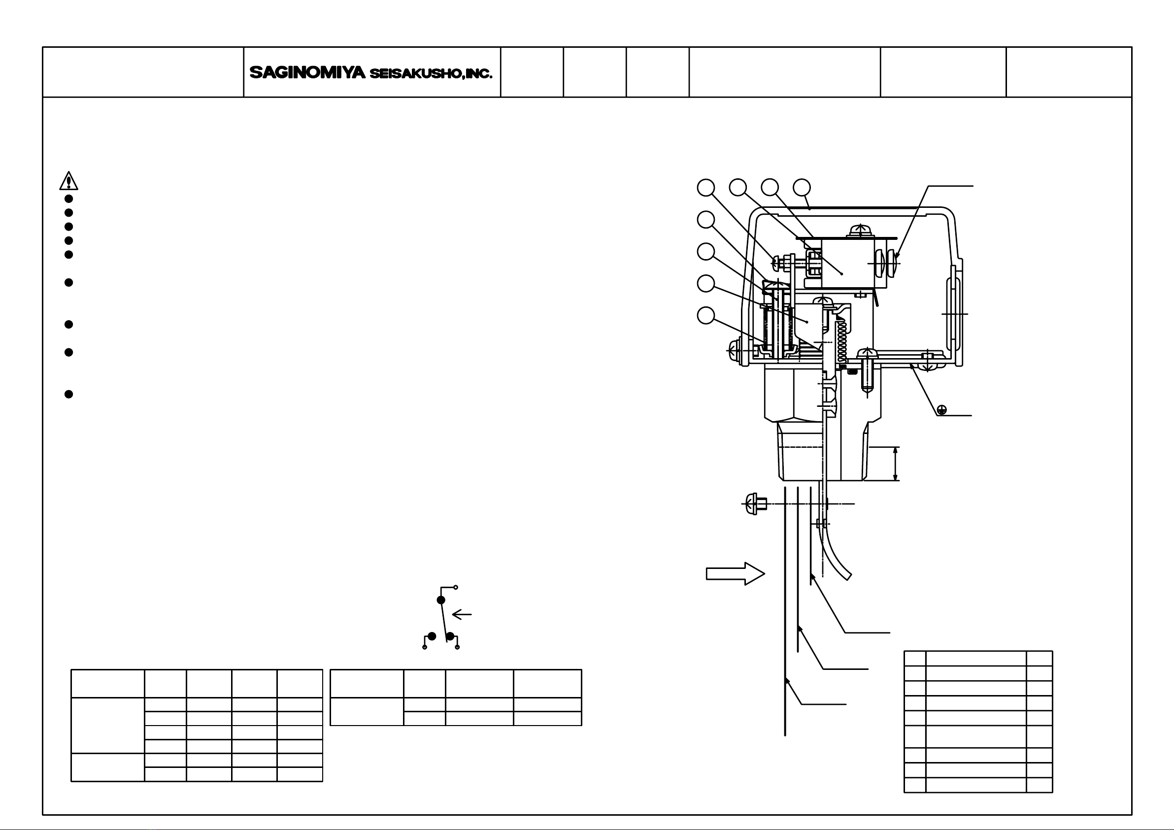
flow switch screwed in shall be 12±1.2mm.
・This table is based on the condition when the depth screwed in is kept within 12±1.2mm.
A FEB.12.2004 REVISION K.Suzuki
A-QS-90003-A
screw⑥ from loosening.
・Never remove the metal fitting ⑤ because this is used to prevent the flow adjusting
・When you turn the flow adjusting screw ⑥ clockwise, the operating point goes up.
dimension “a” in the diagram on the right to that of the
flow switch screwed in shall be 12±1.2mm.
Tee joint (conforming to JIS B 2301).
2/2
by a defect or failure of the Product.
does not include warranty for any consequential damage arising out of or occasioned
Warranty described in this paragraph means the warranty for the Product itself and
or the like and other causes beyond the control of the Company.
① Improper handling or application by user.
② Modification or repair by other than the Company.
③AnyfailuretobecausedbyactsofGod,fire,stormorthelike,war,riot
of the warranty :
be repaired or replaced without charge, provided that any one of followings are out
In case of failure attributable to the Company within such period, the Product shall
year after date of delivery to Buyer.
Unless otherwise agreed by the parties, warranty period of the Product shall be one
I.SCOPE OF WARRANTY
For application requiring extreme high reliability, please contact the Company first.
that is intended to be used under such circumstances that may affect human life.
The product is not designed nor manufactured for an use in such equipment or system
Install and calibrate the Product correctly and then check its operation to confirm
H.LIMIT ON APPLICATION
correct function of the whole system when using.
G.OPERATION CHECK
the paddle 3.
・To install the paddles, install the paddle 1 first then stack the paddle 2 and then
by removing the paddles one by one in order of the longer paddle first.
・When more than two paddles is attached, you can change the flow rate adjustment range
or less, 1+2 for 65A or less and 1+2+3 for 80A or more.
・When the setting value is not specified, the attached paddle 1 can be used for 40A
・Paddle size is in the following order: 1<2<3
100L/min or more: About 20% of the setting value
From 50L/min to less than 100L/min: About 15L/min
Less than 50L/min: About 10L/min
is as follows:
increasing flow operating value) is not determined specifically. The guideline value
・Differential value (difference between the decreasing flow operating value and the
Increasing flow setting value means the flow switch operates when the flow rate increases.
Decreasing flow setting value means the flow switch operates when the flow rate decreases.
・This table is based on the operating point for decreasing flow.
12
2
1
4
1
combination
Piping
150A (6B)
100A (4B)
125A (5B)
100A (4B)
80A (3B)
65A(2/B)
50A (2B)
40A(1/B)
32A(1/B)
25A (1B)
of 2m/s
Adjustment range
Unit: L/min
flow velocityPaddle
2268
1613
1044
612
432
264
163
120
72
MAX
510
135
1890
1342
836
1780
1265
870
594
820
385
480
225
360
355
220
150
100
45
MIN
1781
837
530
1266
595
350
821
386
200
481
226
100
356
151
105
50
18
43
63
1
1
1+2
1+2+3
1
1+2
1+2+3
1
1+2
1+2+3
1
1+2
1+2+3
1
1+2
1
1+2
1
1
Tee joint of JIS.
increasing flow setting value.
・When setting the operating value, refer to either decreasing flow setting value or
・The adjusting screw ④ is exclusively used by our service personnel.
Do not use this screw for adjustment.
the operation of the microswitch.
・If you have changed the setting value, make sure to operate the paddles and check
and if you turn it further, the setting screw breaks off.
But if you turn the screw counterclockwise too much, the operation becomes unstable
When you turn it counterclockwise, the operating point goes down.
operating value set around the minimum flow rate.
・When the operating value is not specified, the flow switch is shipped with the
・For wiring,follow the instructions written on the insulation plate of the microswitch.
・When installing the flow switch to piping, the depth of the
Piping
aRc1
Tee joint of JIS.
If the available Tee joint cannot be installed, adjust the
about 20% compared to the horizontal pipe installation.
However,in the case of a vertical pipe installation, the operating value may change
can be installed in vertical piping.
・For piping of the flow switch, use a commercially available
・Provide a straight pipe section of more than 5 times the piping diameter in front and
・Basically install the switch in horizontal piping with the cover facing upward but it
back of the flow switch. This is used to prevent hunting due to turbulent flow.
F.OPERATION ADJUSTMENT RANGE TABLE
E.OPERATING VALUE SETTING
D.INSTALLATION METHOD
PADDLE TYPE FLOW SWITCH FQS
APR.
1991
Installation and Instruction
Approved by Drawing NumberCatalog NumberNamedatedrawn by
PLRCA.PI.GK0.A1.02 / 520H3006