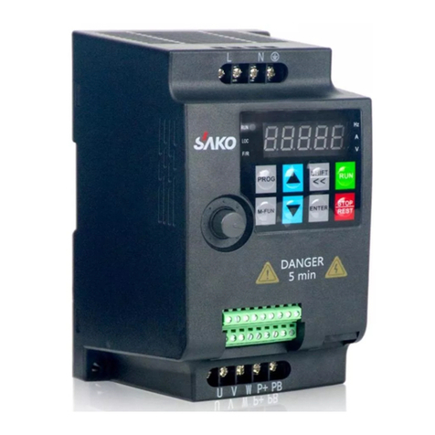
Sako SKI-70 User manual

矢量变频器 vector frequency inverter
SKI-70
使用说明书 V1.0
Operating Specification ManualV1.0
请在使用前仔细阅读本说明书,并请妥善保存以供今后参考。Please read
this specification carefully before use and please safety keep for future
reference.
/SAKO, Always Online


SKI-70 矢量变频器
SKI-70 vector frequency converter
使用说明书
Operating Specification Manual

感谢您选用本公司 70 系列变频器产品。
Thank you for your select and use our 70 series frequency converter products.
请在使用之前仔细阅读本使用手册,以确保正确、安全的使用本产品。
Please read this specification carefully before use to make ensure that correct and safety use this
product.
在使用之前,请务必仔细阅读【安全注意事项】。
Please must read [Safety notices] carefully before use.
请妥善保管本使用手册,以便需要时查阅。若有任何的疑惑,清联系我们的客服或者技术支 持,
我们的专业人员将为您竭诚服务。Please safety keep this operating specification, convenient for
check and read when required. Any questions please contact our customer service or technical support,
our professionals will do best to service for you.
本使用手册提供 70 系列变频器的相关信息,内容包括:
This operating manual provided the relate information of 790 series frequency converter, the contents
include:
◊变频器的安全事项
Safety notices of frequency converter
◊变频器的安装和检查
Installation and inspection of frequency converter
◊变频器的接线说明
Wiring instruction of frequency converter
◊变频器的操作说明
Operating instruction of frequency converter
◊所有参数说明
All parameters instruction
◊通讯协议说明
Communication agreement instruction
◊异常排除
Troubleshooting

本使用手册适合下列使用人员参考:
This operating manual suitable to be consulted by the below operators:
◊系统设计选型人员
System design and model select staffs
◊安装或配线人员
Installation or wiring staffs
◊调机人员
Debugging staffs
◊维护或保养人员
Maintain or maintenance staffs

目录 Content
第一章产品信息 Chapter 1 Product information
1.1 安全信息及注意事项 Safety information and notices .........
01
..........................................m
1.2 命名规则 Naming rules..............................................................
1.3 SKI-70 变频器系列指标 SKI790 frequency converter series index
1.4 产品外型图、安装孔位尺寸 Product profile figure and installation hole
size
1.5 变频器的保修说明 Warranty instruction of frequency converter
U丄
01
......................................... 02
......................................... 02
•……03
第二章电气安装 Chapter 2 Electric installations
04
.......................................... n/
2.1 主电路端子及接线 Main electric circuit terminals and wiring
第三章操作显示 Chapter 3 Operating display
3.1 操作与显示界面介绍 Operating and display interface instruction
08
08
第四章功能参数表 Chapter 4 Function parameters table
4.1 基本功能参数简表 Basic function parameters simple table
10
10
第五章故障诊断及对策 Chapter 5 Failure diagnose and
policies
5.1 故障报警及对策 Failure alarm and policies............................
5.2 常见故障及其处理方法 Common failure and treatment method
5.3 保修协议 Warranty agreement..................................................
44
44
49
......................................... 50

01
第一章产品信息 Chapter 1 Product information
1.1 安全信息及注意事项 Safety information and notices
安全定义:在本手册中,安全注意事项分以下两类:
Safety definition: the safety notices in this manual divided into the below two types:
危险:由于没有按要求操作造成的危险,可能导致重伤,甚至死亡的情况;
Danger: the danger caused by that operation not according to requirements maybe caused serious hurt,
even though dead;
注意:由于没有按要求操作造成的危险,可能导致中度伤害或轻伤,及设备损坏的情况;请
用户在安装、调试和维修本系统时,仔细阅读本章,务必按照本章内容所要求的安全注意 事
项进行操作。如出现因违规操作而造成的任何伤害和损失均与本公司无关。Attention: the
danger caused by that operation not according to requirements maybe caused medium hurt or minor
hurt and equipment damaged; please read this chapter carefully when user install, debug and maintain
this system, must operating according to the required safety notices in the content of this chapter. Any
hurt and loss which caused by the operation which not according to the stipulates all are unconcerned
with our company.
1.2 命名规则 Naming rules
70 - 2D2 - 4
电压等级:Voltage grade: 1:单相 220V 1: single phase 220V
4:三相 380V 4: Three phase 380V
I---------------------------功率等级:0D75:0.75KW Power grade: 0D75: 0.75KW
1D5:1.5KW 1D5: 1.5KW
2D2:2.2KW 2D2: 2.2KW
4D0:4KW 5D5: 5.5KW
7D5:7.5KW
--------------------------------------------- 型号:70 Model: 70

02
1.3SKI-70 变频器系列指标 SKI70 frequency converter series index
变频器型号
Frequency converter
model
额定功率 Rated
power (KW)
额定输出电流 Rated
output current (A)
适配电机 Adapted motor
kW
HP
单相电源 Single phase power supply: 220V, 50Hz/60Hz
70-0D75-1
0.75
4.0
0.75
1
70-1D5-1
1.5
7.0
1.5
2
70-2D2-1
2.2
9.6
2.2
3
70-4D0-1
4
17
4
5.5
三相电源 Three phase power supply: 380V, 50Hz/60Hz
70-0D75-4
0.75
2.1
0.75
1
70-1D5-4
1.5
3.8
1.5
2
70-2D2-4
2.2
5.1
2.2
3
70-4D0G-4
4
9
4
5.5
70-5D5G-4
5.5
13
5.5
7.5
70-7D5G-4
7.5
16
7.5
10
表1-1 SKI-70 变频器型号与技术数据 Table 1-1 SKI-70 frequency converter model and technical
data
1.4 产品外型图、安装孔位尺寸 Product profile figure and installation hole
size
1.4.1 产品外型图 Product profile figure

02
图1-2 SKI-70 塑胶结构外型尺寸及安装尺寸示意图 Fig 1-2 Profile size and installation size
figure of SKI-70 plastic structure

3
L4.2 外引键盘的外型尺寸 Profile size of outer lead keyboard

4
第二章电气安装 Chapter 2 Electric installations
2.1 主电路端子及接线 Main electric circuit terminals and wiring
1)变频器主回路端子说明:Frequency converter main circuit terminal instruction:
端子标记 Terminal
marks
名称 Name
说明 Instruction
R,S,T/L、N
电源输入端子 Power supply input
terminals
三相 380V/单相 220V 交流电源连接点
Connection point of three-phase 380V /
single-phase 220V AC power supply
P+,PB
制动电阻连接端子 Brake electric
resistance connect terminals
连接制动电阻 Connect brake electric
resistance
U, V,W
变频器输出端子 Frequency
converter output terminals
连接三相电动机 Connect three phase motor
舎
接地端子 Grounding terminals
2.1.2 变频器控制回路接线方式 Wiring method of frequency converter control circuit

5
图2-2 变频器控制回路接线方式 Fig 2-2 Wiring method of frequency converter control circuit

6
2.1.3控制端子说明 Control terminals instruction
控制回路端子布置图如下示:The control circuit terminals layout diagram shown as the below:
2.1.4 控制端子功能说明 Control terminal function instruction:
类别
Category
端子符号
Terminal
symbol
端子名称 Terminal
name
功能说明 Function instruction
电源
Power
supply
10V-GND
外接 10V 电源 Outer
connect 10V power
supply
向外提供+10V 电源,最大输出电流:Outer provide
+10V power supply, the max output current:
150mA(带短路保护)一般用作外接电位器工作 电
源,电位器阻值范围:
1kΩ〜5kΩ Generally, 150mA
(with short circuit protection) used as the working
power supply of outer connect electric potential
device, electric potential device electric resistance
value range: 1kΩ〜5kΩ
24V-GND
外接 24V 电源 Outer
connect 24V power
supply
向外提供+24V 电源,一般用作数字输入输出端 子
工作电源和外接传感器电源 Outer provide +24V
power supply, generally, it used as working power
supply of digit input and output terminal and outer
connect sensor power supply
最大输出电流:200mA The max output current:
200mA

7
模拟 端
子
Analog
terminal
AI1-GND
模拟量输入端子 1
Analog quantity input
terminal 1
1.输入范围:DC 0V~10V/0mA~20mA,由参数
P4-37 决定
1. Input range: DC 0V ~ 10V / 0ma ~ 20mA, which is
determined by parameter p4-37
2.输入阻抗:电压输入时阻抗 22kΩ,电流输入时
阻抗 500Ω
2.Input impedance: 22K Ωfor voltage input and 500
Ωfor current input
AI2-GND
模拟量输入端子 2
Analog quantity input
terminal 2
1. 1、输入范围:DC 0V~10V/0mA~20mA,由参
数P4-37 决定
1. Input range: DC 0V ~ 10V / 0ma ~ 20mA, which is
determined by parameter p4-37
2. 2、输入阻抗:电压输入时阻抗 22kΩ,电流输入
时阻抗 500Ω
2. Input impedance: 22K Ω for voltage input and 500
Ω for current input
AO1-GND
模拟量输出端子 1
Analog quantity input
terminal 1
输出电压范围:0V-10V Output voltage range:
0V-10V
输出电流范围:
0mA〜20mA, 4~20mA
(P5-23 可 选
择)Output current range: 0mA〜20mA, 4~20mA
(P5-23 optional)

8
数字 输
入Digit
input
X1-GND
数字输入 1 Digit
input 1
HDI 除有 X1-X4 的特点外,还可作为高速脉冲 输
入通道。HDI still can be as high speed pulse input
passageway except the characteristics of X1-X4.
最高输入频率:50kHz The highest input
frequency: 50kHz
1.输入阻抗:1kΩ Input impedance: 1kΩ
2.电平输入时电压范围:5V-30V Electric level
input voltage range: 5V-30V
X2-GND
数字输入 2 Digit
input 2
X3-GND
数字输入 3 Digit
input 3
X4-GND
数字输入 4 Digit
input 4
HDI-GND
数字输入 5 Digit
input 5
A+B-
RS485 通讯 RS485
communication
A+为485 通讯差分信号正输入,B-为差分信号 负
输入 A+ is positive input of 485 communication
difference signal, B- is negative input of difference
signal
数字 输
出Digit
output
Y1-GND
集电极开路输出
Collector open circuit
output
当作为集电极开路输出端子 As the collector open
circuit output terminal
HDO-GND
高速脉冲输出 High
speed pulse output
受功能码 P5-00 "HDO 端子输出模式选择”约
束Restrained by function code P5-00 “HDO terminal
output mode selection”
当作为高速脉冲输出,最高频率到 50kHz;The
highest frequency achieved 50kHz when as
high speed pulse output;
当作为集电极开路输出,与 Y1 规格一样。Same
specification with Y1 when as collector open circuit
output
K1A-K1B-
K1C
继电器 1端子
Electric relay 1
terminal
触点描述:Contact description:
A:公共点 public point
B:常闭点 normally close point
C:常开点 normally open point
触点驱动能力:Contact drive capacity:
AC250V, 3A, COSφ=0.4.
DC 30V, 1A
K2A-K2B-
K2C
继电器 2端子
Electric relay 2
terminal
2.1.5 信号输入端子接线说明:Signal input terminal wiring instruction:

9
因微弱的模拟电压信号特别容易受到外部干扰,所以一般需要用屏蔽电缆,而且配线距 离
尽量短,不要超过 20mo在某些模拟信号受到严重干扰的场合,模拟信号源侧需加滤波 电容器
或铁氧体磁。Because the weak analog voltage signal especially been outer disturbed easily, so,
generally need shielded cable, and the cable distribute distance should do best to be short, not exceed
20m. The analog signal source side need additionally add filter wave electric capacitor or iron-oxygen
magnetism in the place where some analog signals seriously disturbed.

10
第三章操作显示 Chapter 3 Operating display
3.1 操作与显示界面介绍 Operating and display interface instruction
用操作面板,可对变频器进行功能参数修改、变频器工作状态监控和变频器运行控制(起
动、停止)等操作,其外型及功能区如下图所示:Able to process the operations such as modify the
function parameters of frequency converter, monitor working status of frequency converter and control
frequency converter running (start and stop) through operating panel, the profile and function area
shown as the below diagram:

11
1)功能指示灯说明:Function indicate lamp instruction:
◊ RUN:灯灭时表示变频器处于停机状态,灯亮时表示变频器处于运转状态。RUN: lamp
extincted means the frequency converter be at stop machine status, lamp lighting means the frequency
converter be at running status.
LOCAL/REMOTE 熄灭 extincted
面板启停控制 Panel start-stop control
LOCAL/REMOTE 常亮 normally lighting
端子启停控制 Terminal start-stop control
LOCAL/REMOTE 闪烁 flashing
通讯启停控制 Communication start-stop control
◊ LOCAL/REMOT:键盘操作、端子操作与远程操作(通信控制)指示灯:
LOCAL/REMOT: keyboard operation, terminal operation and remote operation
(communication control) indicate lamp:
◊ FWD/REV:正反转指示灯,灯亮表示处于正转状态。FWD/REV:forward and reverse
running indicate lamp, lamp lighting means it be at forward status.
◊ TUNE/TC:调谐/转矩控制/故障指示灯,灯亮表示处于转矩控制模式,灯慢闪表示处 于
调谐状态,灯快烁表示处于故障状态。TUNE/TC: tune/torque control/failure indicate
lamp, lamp lighting means it be at torque control mode, lamp slow flashing means it
be at tune status, lamp quick flashing means it be at failure status.
2)单位指示灯:Unit indicate lamp:
Hz
频率单位 Frequency unit
A
电流单位 Current unit
V
电压单位 Voltage unit
RPM(Hz+A)
转速单位 Speed unit
%(A+V)
百分比 Percentage
3)数码显示区:Digit display area:
5位LED 显示,可显示设定频率、输出频率,各种监视数据以及报警代码等。5 bit LED display,
able to display the setting frequency and output frequency, various monitor data and alarm code, etc.

12
4)键盘按钮说明表 Keyboard button instruction table
按键 Keys
按键名称 Key name
按键功能 Key function
PRG
编程键 Programming key
一级菜单进入或退出 Level I menu enter into or withdraw
FUNC
确认键 Confirm key
逐级进入菜单画面、设定参数确认 Level to level enter into menu tableau,
confirm setting parameters
▲
递增键 Progressively
increase key
数据或功能码的递增 Data or function code progressively increase
▼
递减键 Progressively
reduce key
数据或功能码的递减 Data or function code progressively reduce
►
移位键 Shift key
在停机显示界面和运行显示界面下,可循环选择显示 参数;在修改参数
时,可以选择参数的修改位 Able to circling select the display parameters
under the stop machine indicate interface and running display interface; able to
select the modify bit of parameter when modifying parameters
RUN
运行键 Running key
在键盘操作方式下,用于运行操作 Used in running operation under keyboard
operating method
STOP/RES
停止/复位 Stop/reset
运行状态时,按此键可用于停止运行操作;故障报 警状态时,可用来复
位操作,该键的特性受功能码 P7-02 制约。Press this key able to used in stop
running operation at running status; able to be used in reset operation at failure
alarm status, the characteristics of this key restrained by function code P7-02.
MF.K
多功能选择键 Multiply
functions select key
根据 P7-01 作功能切换选择 Process function shift selection according to
P7-01
表3-1 键盘功能表 Table 3-1 Keyboard function table
第四章功能参数表 Chapter 4 Function
parameters table
4.1 基本功能参数简表 Basic function parameters simple table
“☆” :表示该参数的设定值在变频器处于停机、运行状态中,均可更改;means the setting
value of this parameter in frequency converter be at stop machine and running status, all can be
modified;
“★” :表示该参数的设定值在变频器处于运行状态时,不可更改;means the setting value of
this parameter in frequency converter be at running status, can’t be modified;
“•” :表示该参数的数值是实际检测记录值,不能更改;means the value of this parameter is
actual test record value, can’t be modified;
Table of contents
Other Sako Inverter manuals
Popular Inverter manuals by other brands

Generac Power Systems
Generac Power Systems 9592-3 owner's manual

HP
HP 70301A Installation and verification manual

Sunforce
Sunforce PRO SERIES 11240 manual

Miller
Miller Invision 352 MPa Auto-Line CE Technical manual

SMC Networks
SMC Networks ZL3 Series Operation manual

VOLTWERK
VOLTWERK VS 3 operating manual