EG4 18KPV User manual

User Manual
EG4 18KPV
© 2023 EG4 Electronics, LLC. All rights reserved.
Version 2.0.2 | Information subject to change without notice.
Scan this QR code to
navigate to the product
page for the latest
manuals and spec
sheets!

1
Table of Contents
1 Abbreviations ...........................................................................................................................................................4
2 Safety........................................................................................................................................................................5
2.1
Safety Instructions ............................................................................................................................................5
2.2
Important Safety Notifications .........................................................................................................................5
3 Brief Introduction .....................................................................................................................................................7
3.1
System Diagrams ..............................................................................................................................................7
4 Installation................................................................................................................................................................8
4.1
Packaging List and Placement...........................................................................................................................8
4.2
Location Selection and Installation...................................................................................................................8
4.2.1 Requirements for Installation Location ....................................................................................................8
4.2.2 Installing the Inverter ...............................................................................................................................9
4.2.3 Mounting Steps ......................................................................................................................................10
4.3
Connection Overview .....................................................................................................................................11
4.3.1 System Connections ...............................................................................................................................11
4.4
PV Connection ................................................................................................................................................14
4.4.1 Connecting PV to the Inverter ................................................................................................................14
4.4.2 String Sizing ............................................................................................................................................15
4.4.3 Steps for PV Wiring ................................................................................................................................17
4.5
Battery Connection.........................................................................................................................................17
4.5.1 Connecting Batteries to the Inverter......................................................................................................17
4.5.2 Battery Power Cable Connection............................................................................................................18
4.5.3 Battery Communication Cable Connection ............................................................................................18
4.5.4 AC Wiring Information ...........................................................................................................................20
4.5.5 Steps for AC Connection.........................................................................................................................21
4.5.6 CT/Meter Connection.............................................................................................................................21
4.6
Working with a Generator ..............................................................................................................................23
4.6.1 Generator System Connection ...............................................................................................................23
4.6.2 Connecting the Generator Start Signal (Dry Contact).............................................................................24
4.6.3 Generator Start and Stop Settings .........................................................................................................24
4.7
Off-Grid ..........................................................................................................................................................25
4.7.1 Off-Grid Wiring.......................................................................................................................................25

2
4.8
AC Coupling Installation Connection ..............................................................................................................25
4.8.1 AC Coupling Settings...............................................................................................................................26
4.9
Parallel System Connection ............................................................................................................................27
4.9.1 Connections for Parallel System .............................................................................................................27
4.9.2 Parallel Information Display ...................................................................................................................27
4.9.3 Parallel Configuration .............................................................................................................................28
4.10
Grid, Load, and AC Connection.......................................................................................................................29
4.10.1 Grid Type and Regulation Connection....................................................................................................29
5 Grid and Load Connections for Split- Phase Service..............................................................................................29
5.1
Decision Tree and Wiring Diagrams................................................................................................................29
6 End User Settings ...................................................................................................................................................46
6.1
Application Settings .......................................................................................................................................46
6.2
Paralleling Settings.........................................................................................................................................46
6.3
Charge Settings ..............................................................................................................................................47
6.4
Generator Charge Settings.............................................................................................................................48
6.5
Discharge Settings..........................................................................................................................................48
7 Installer Settings.....................................................................................................................................................49
7.1
Common Settings...........................................................................................................................................49
7.2
Application Settings .......................................................................................................................................50
7.3
Grid Connect Settings ....................................................................................................................................51
7.4
Charge Settings ..............................................................................................................................................53
7.5
Generator Charge Settings.............................................................................................................................54
7.6
Discharge Settings..........................................................................................................................................54
8 Monitor System Setup............................................................................................................................................56
8.1
Wi-Fi/4G Dongle Connection .........................................................................................................................56
8.2
Third-Party RS485 Communication................................................................................................................57
8.3
Online Monitoring System User Interface .....................................................................................................58
8.3.1 Using the Web interface to set your Wi-Fi password. ...........................................................................58
8.3.2 Dashboard (Monitor Tab) ......................................................................................................................59
8.3.3 Data tab..................................................................................................................................................60
8.3.4 Configuration Tab...................................................................................................................................65
8.3.5 Overview ................................................................................................................................................66
8.3.6 Maintenance ..........................................................................................................................................67
9 Firmware Updates..................................................................................................................................................68

3
9.1
Firmware Update via EG4 Electronics App ....................................................................................................68
9.2
Firmware Update via Hard-Wired Ethernet Connection ...............................................................................68
9.3
Firmware Update via Monitor Center (website)............................................................................................70
10 Smartphone App Setup.........................................................................................................................................71
10.1
Local Monitoring Setup with the EG4 Monitor app.......................................................................................73
10.2
Troubleshooting Wi-Fi module ......................................................................................................................73
11 Operation Guide.....................................................................................................................................................74
11.1
Operation Mode and Function ......................................................................................................................74
11.1.1 Self-Usage Mode....................................................................................................................................74
11.1.2 Charge First Mode..................................................................................................................................75
11.1.3 AC Charger Mode...................................................................................................................................76
11.1.4 Grid Peak-Shaving Function ...................................................................................................................76
11.1.5 Smart Load Function ..............................................................................................................................76
11.2
Rapid Shutdown (RSD) ...................................................................................................................................77
11.2.1 External RSD...........................................................................................................................................77
11.2.2 External RSD Wiring Instructions ...........................................................................................................78
11.3
LCD Screen .....................................................................................................................................................79
11.3.1 Viewing Information and Alarm Fault/Record.......................................................................................79
11.3.2 Setting Parameters.................................................................................................................................80
11.4
Inverter Start-Up and Shutdown Procedure..................................................................................................84
11.4.1 Starting up the inverter..........................................................................................................................84
11.4.2 Shutting down the inverter....................................................................................................................85
12 Troubleshooting & Maintenance ............................................................................................................................85
12.1
Regular Maintenance.....................................................................................................................................85
12.2
LED Description ..............................................................................................................................................85
12.3
Troubleshooting Based on LCD Screen ..........................................................................................................86
12.3.1 Faults on the LCD and Fault List .............................................................................................................86
12.3.2 Alarm on the LCD and Alarm List ...........................................................................................................88
13 Standards and Certifications ...................................................................................................................................90
14 Technical Specifications ..........................................................................................................................................90

4
1Abbreviations
• AWG – American Wire Gauge
• A — Amp(s)
• Ah — Amp hour(s)
• AC — Alternating Current
• AHJ — Authority Having Jurisdiction
• ANSI — American National Standards Institute
• BMS — Battery Management System
• DC — Direct Current
• DIP — Dual In-line Package
• DOD – Depth of Discharge
• EG – Equipment Ground
• EGS – Equipment Grounding System
• EPS – Emergency Power System
• ESS – Energy Storage System
• E-Stop NO — Emergency Stop Normally Open
• GE – Grounding Electrode
• GEC – Grounding Electrode Conductor
• GES – Grounding Electrode System
• In. lbs. — Inch Pounds
• kW — Kilowatt
• kWh — Kilowatt-hour
• LFP — Lithium Iron Phosphate or LiFePO4
• mm — Millimeter(s)
• mV — Millivolt(s)
• NEC — National Electrical Code
• NFPA — National Fire Prevention Association
• Nm — Newton meters
• PC — Personal Computer
• PCB – Printed Circuit Board
• PE – Protective Earth (G or Ground)
• PPE — Personal Protective Equipment
• PV — Photovoltaic
• RSD — Rapid Shut Down
• SOC — State of Charge
• V — Volt(s)

5
2Safety
2.1
Safety Instructions
International safety regulations have been strictly observed in the design and testing of the inverter.
Before beginning any work, carefully read all safety instructions, and always observe them when work-
ing on or with the inverter. The installation must follow all applicable national or local standards and
regulations.
Incorrect installation may cause:
•injury or death to the installer, operator or third party
•damage to the inverter or other attached equipment
2.2
Important Safety Notifications
There are various safety concerns that must be carefully observed before, during, and after the installa-
tion, as well as during future operation and maintenance. The following are important safety notifica-
tions for the installer and any end users of this product under normal operating conditions.
Dangers of High Voltages and Large Current
1. Beware of high PV voltage. Please install an external DC disconnect switch or breaker and
ensure it is in the “off” or “open” position before installing or working on the inverter. Use a
voltmeter to confirm there is no voltage present to avoid electric shock.
2. Beware of high grid voltage. Please ensure the AC switch and/or AC breaker are in the “off” or
“open” position before installing or working on the inverter. Use a voltmeter to confirm there is
no voltage present to avoid electric shock.
3. Beware of high battery current. Please ensure that the battery module breakers and/or on/off
switches are in the “open” or “off” position before installing or working on the inverter. Use a
voltmeter to confirm there is no voltage present to avoid electric shock.
4. Do not open the inverter while it is operating to avoid electric shock and damage from live
voltage and current within the system.
5. Do not make any connections or disconnections (PV, battery, grid, communication, etc.)
while the inverter is operating.
6. An installer should make sure to be well protected by reasonable and professional insulative
equipment [e.g., personal protective equipment (PPE)].
7. Before installing, operating, or maintaining the system, it is important to inspect all existing
wiring to ensure that it meets the appropriate specifications and conditions for use.
8. Ensure that the PV, battery, and grid connections to the inverter are secure and proper to
prevent damage or injuries caused by improper installation.

6
Warning
1. All work on this product (system design, installation, operation, setting, configuration,
and maintenance) must be carried out by qualified personnel. To reduce the risk of electric shock,
do not perform any servicing other than those specified in the operating instructions unless you
are qualified to do so.
2. Read all instructions before installing. For electrical work, follow all local and national wiring
standards, regulations, and these installation instructions.
3. Make sure the inverter is properly grounded. All wiring should be in accordance with the
National Electrical Code (NEC), ANSI/NFPA 70.
4. The inverter and system can inter-connect with the utility grid only if the utility provider per-
mits. Consult with your local AHJ (Authority Having Jurisdiction) before installing this product
for any additional regulations and requirements for your area.
5. All warning labels and nameplates on this inverter should be clearly visible and must not be
removed or covered.
6. The installer should consider the safety of future users when choosing the inverter’s correct
position and location as specified in this manual.
7. Please keep children away from touching or misusing the inverter and relevant systems.
8. Beware! The inverter and some parts of the system can be hot when in use, please do not touch
the inverter’s surface or most of the parts when they are operating. During operation, only the
LCD and buttons should be touched.
DISCLAIMER
EG4 reserves the right to make changes to the material herein at any time without notice. You may refer
to the EG4 website at www.eg4electronics.com for the most updated version of our manual.
7
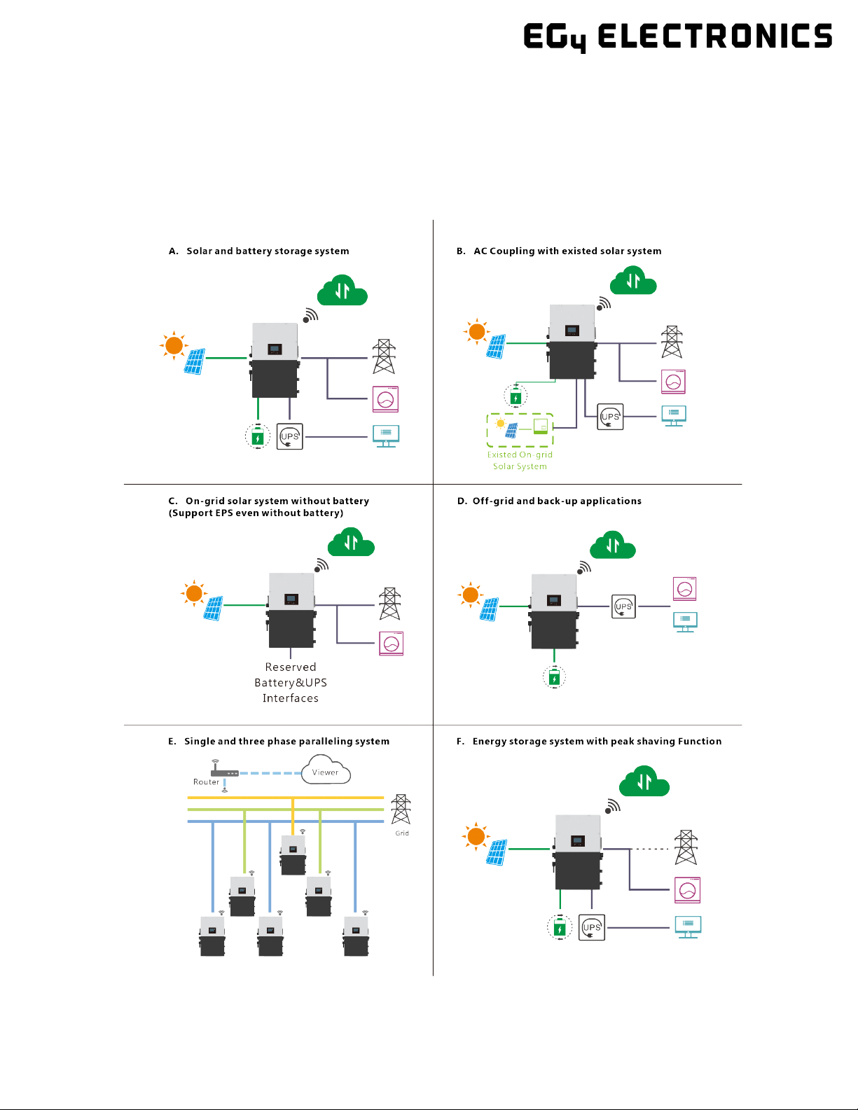
3Brief Introduction
3.1
System Diagrams
This unit and its associated system are suitable for the following applications:

8
4Installation
4.1
Packaging List and Placement
Packaging List
When the product is unpacked, the contents should match those listed below:
Pictures for reference only, subject to our available products.
4.2
Location Selection and Installation
4.2.1 Requirements for Installation Location
1. The mounting wall should be strong enough to bear the weight of the inverter.
2. Please maintain the minimum clearances presented below for adequate heat dissipation.

9
3. Never position the inverter in direct sunlight. Please refer to the figure below and choose a well-
shaded site or a shed to protect the inverter from direct sunlight. PROTECT the LCD screen from
excessive UV exposure.
4. The inverter should be installed upright on a vertical surface.
4.2.2 Installing the Inverter
The inverter is designed to be wall-mounted and should be installed on a vertical, solid, mounting sur-
face, such as brick, concrete, or other non-combustible material. Two or more people may be needed
to install the inverter due to its weight. The slots on the mounting bracket can accommodate various
stud spacings from 12 in. (305 mm) to 16 in. (406 mm).
10
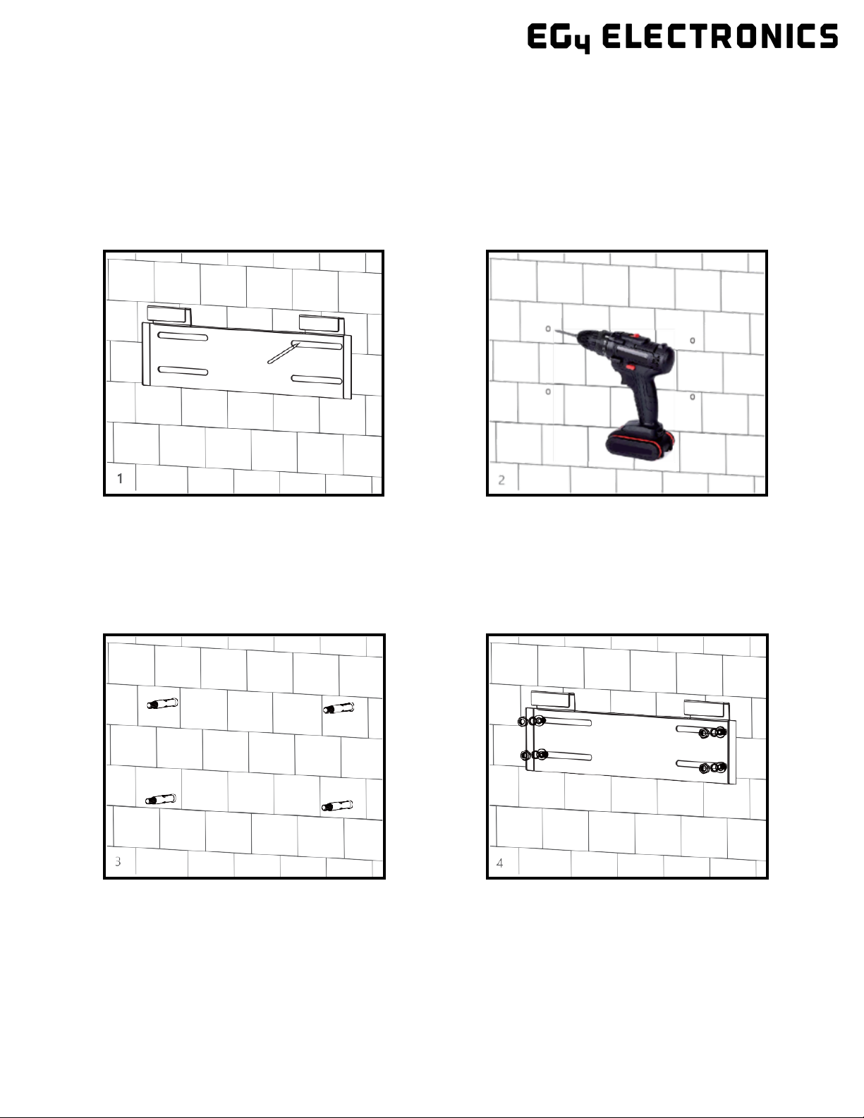
4.2.3 Mounting Steps
For installation on brick or concrete:
1. Mark the drill hole positions with the mounting bracket.
2. Drill four, 5/16 in. (48 mm) diameter holes, making sure the holes are deeper than 2 in. (50 mm).
3. Insert the expansion bolts into the holes and tighten.
4. Use the corresponding nuts and washers (packaged together with the expansion bolts) to install
and affix the wall-mount bracket onto the wall.

11
5. Hang the inverter on the wall-mount bracket and lock the inverter on the wall using two (2) self-
tapping screws on the top of the inverter (not included with inverter). Lock the safety screws on the
left and right sides.
For installation on concrete board with wood studs:
Fasten the mounting bracket to the studs with four (4) heavy duty wood screws, then hang the inverter
on the bracket and lock the inverter on the wall with two (2) self-tapping screws.
Please note that the wood screws and self-tapping screws are not provided with the inverter. Installers
will need to acquire the screws before installation.
4.3
Connection Overview
4.3.1 System Connections
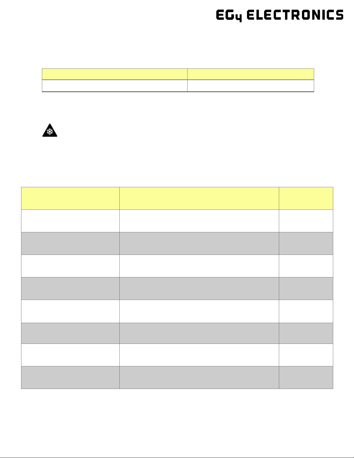
Breaker selection recommendation for both DC and AC
Breaker/Switch
Recommended Breaker Rating
PV Input
PV Disconnect Switch:600VDC/32A
AC Input/Output
See breaker notes on wiring diagrams (Page 28)
Generator
240VAC /100A

12
Overview of the Cable Box
*PE stands for “Protective Earth” and is another way to label the ground on the system. Any instances
of “PE” that may appear in the manual will be referred to GROUND (G) henceforth.
Integrated Bonded Load
Breaker
L1 :200A
L2: 200A
Integrated Bonded Bat.
Breaker 200A × 2

13
Overview of Connection Ports
a. Battery communication port (CAN &
RS485)
b. CT interface (refer to Section 4.5.6 for
CT connection)
c. INV 485: debugging port
d. Parallel communication port (refer to
Section 4.9 for parallel connection)
e. Fans 1/2/3
f. Temp sensor connection for lead- acid
battery
g. Meter 485B & 485A: for meter com-
munication
h. ±12V: reserved for customer to use –
500mA max
i. CAN matching resistance: set DIP
switch when using inverters in parallel
j. Connection for generator auto-start
function: GEN (NO, NC)
k. Reserved: DRY (NO, NC)
l. LCD UI upgrade port
m. RSD Terminals
14
4.4
PV Connection
4.4.1 Connecting PV to the Inverter
Cable Requirements:
Cable Size
Minimum Insulator Voltage
10 AWG – 6AWG (Max) (6 mm2– 16 mm2) 600V
Consult with your installer to ensure that appropriate cable sizing is used due to various factors such as
voltage drop and VOC.
Reminder
Verify the lowest ambient temperature of the installation location. The rated VOC on the solar module
nameplate is obtained at STC (77°F/25°C). As the ambient temperature drops, the solar module VOC
increases. Please ensure the maximum solar string voltage, corrected at the lowest temperature, does
not exceed the inverter’s maximum input voltage of 600V.
PV Input Data Description Parameter
DC Input Voltage Range
Range required for the unit to operate up to max input
100–600 VDC
Unit Startup Voltage
Voltage needed for the LCD to turn on
100 VDC
Load Output Minimum Voltage
Minimum voltage needed to output power on Load side
>140 VDC
MPP Operating Voltage Range
Range where the MPPT can track
120–500 VDC
Full Power MPPT Voltage Range
Range where the MPPT operates at max capabilities
230–500 VDC
Nominal MPPT Voltage The MPPT will operate most optimally at this voltage
360 VDC
Maximum Utilized Solar Power Number of watts the unit can utilize from array after
con-
sidering all power loss factors
18,000W
Rec. Maximum Solar Input The suggested PV power input into the device for it to uti-
lize the full 18kW of PV that it can process.
21,000W
15
4.4.2 String Sizing
When solar modules are put in a series string, the voltage multiplies times the number of modules and the
amperage stays the same as each module.
For example: Using solar modules that have a 40 Voc (77ºF) with an amperage of 10 Amps (Imp) - 10 mod-
ules wired in a series string would have a Voc of 400 VDC (at 77ºF) and a string amperage of 10 Amps.
When the temperature lowers the voltage can rise above the maximum allowed by the inverter and dam-
age will result.
CAUTION: To determine how many modules you can have per string; first verify the lowest possible ambi-
ent temperature of the installation location. Next, find the rated Voc, Vmp, Isc and Imp of the solar module
at 25ºC and the temperature coefficients for voltage and power. Then calculate highest possible Voc for
the entire string when the ambient temperature falls to the lowest possible ambient temperature upon
sunrise. To make this calculation, use a string calculator or consult your solar designer or solar electrician.
DANGER! -DAMAGE WILL OCCUR if the string voltage on a cold sunny morning exceeds the inverter’s maxi-
mum input voltage of 600V!

16
String Sizing continued…
Finally, calculate the maximum current of the string so as not to exceed the Inverter’s MPPT circuit ratings.
Double check if the calculated Vmp range is within the 230-500 VDC optimal MPPT circuit operating range.
Consult a solar designer if needed.
FOR ALL MODULES, THE CALCULATIONS NEED TO BE PERFORMED OR VERIFIED BY USING A STRING CAL-
CULATOR OR CONSULTING A PROFESSIONAL.
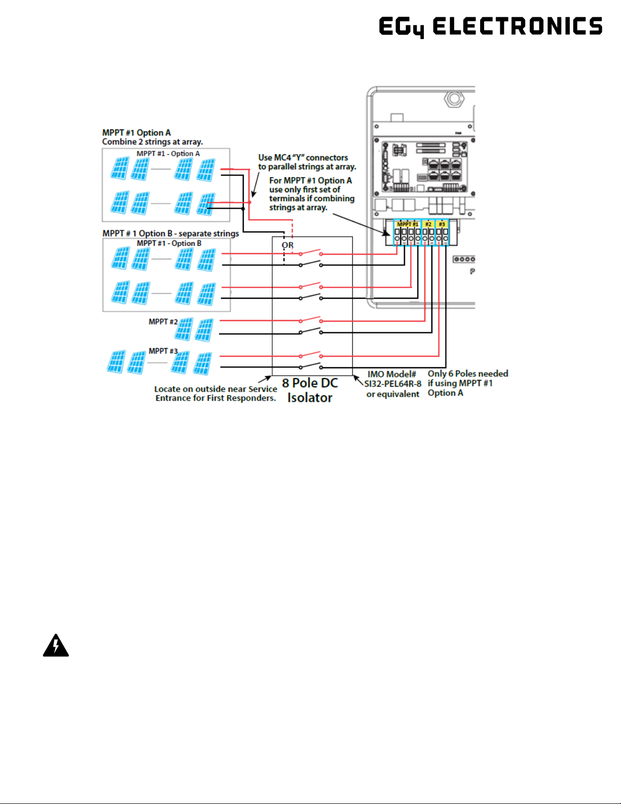
The inverter has three MPPT PV charging circuits. MPPT #1 will use up to 25 amps which means two strings
can be paralleled for any modules having less than a 12.5 A (Imp) rating. MPPT #2 and MPPT #3 will use up
to 15 Amps each so they are usually limited to one string. (Unless you have a module with < 7.5 Amps)
Each string ideally should contain the same model, brand, and quantity of panels for ease of design, racking
and wiring. However, varying string sizes can be used for unique MPPTs. If two strings are used for MPPT
#1 they MUST be the same model, brand and # per string. MPPT#2 and MPPT #3 could differ in model,
brand and # per string (same make/model per string) on condition that each string complies with the low-
est temperature (maximum string number) and maximum amperage calculations above.
All panels on a series/parallel string should face the same orientation and hopefully be exposed to roughly
the same shading across the string. Consideration should be placed on string location and wiring order on
the racking to minimize shading effects. One shaded module can disproportionately reduce output for the
entire string so avoiding linear strings in favor of rectangular strings can increase output. Optimizers can
also achieve this.
The inverter will limit the total MPPT current to 25 A for MPPT #1 and to 15 Amps for MPPT #2 and 15
Amps for MPPT #3.
Note: The array can have a higher Imp than the 25A/15A specified, but the MPPTs will not make full use of
the extra current. Having an array that can produce more current than the MPPTs will bring in is useful for
increasing morning, winter or cloudy day solar production.
17
4.4.3 Steps for PV Wiring
Note: According to the NEC (National Electric Code) in the USA all PV Systems above 50V must have one current-carry-
ing conductor connected to the ground/earth. With that, all exposed metal parts of the system must be grounded re-
gardless of voltage. DO NOT GROUND NEGATIVE PV LINE, ONLY SOLAR PANEL FRAMES.
4.5
Battery Connection
4.5.1 Connecting Batteries to the Inverter
Cable Requirements (suggestions based on distance and battery bank quantity):
# of cables
Cable Size (90°C)
Max. Distance
Torque for cable connection
2 sets
1/0 AWG (53.5 mm2) 10 ft. 165 in. lbs. (16.6 Nm)
2 sets
2/0 AWG (67.4 mm
2
)
20 ft.
165 in. lbs. (16.6 Nm)
1 set
4/0 AWG (107 mm2) 10 ft. Max. 275 in. lbs. (31.1 Nm)
1 set
250 kcmil (127 mm
2
)
20 ft.
Max. 275 in. lbs. (31.1 Nm)
1. Ensure all breakers and disconnect switches are in the OFF
position before connecting or disconnecting wires. Use a
voltmeter to confirm there is no voltage present.
2. Strip off 1/4 – 5/16 in. (6 – 8 mm) insulation on the PV
string’s positive and negative conductors.
3. Use wire ferrules for the PV string conductors if they are
stranded wire.
4. Insert the conduit fitting into the opening for the PV con-
nection and tighten it from the inside using the counter
nut.
5. Route the PV conductors through the conduit fitting and into
the inverter.
6. Secure the PV conductors in place into the inverter inputs.
Verify that they are secured properly by lightly pulling on
them.
7. Ensure the conduit and conduit fittings are fastened reliably
and the cable entry holes are sealed.
18
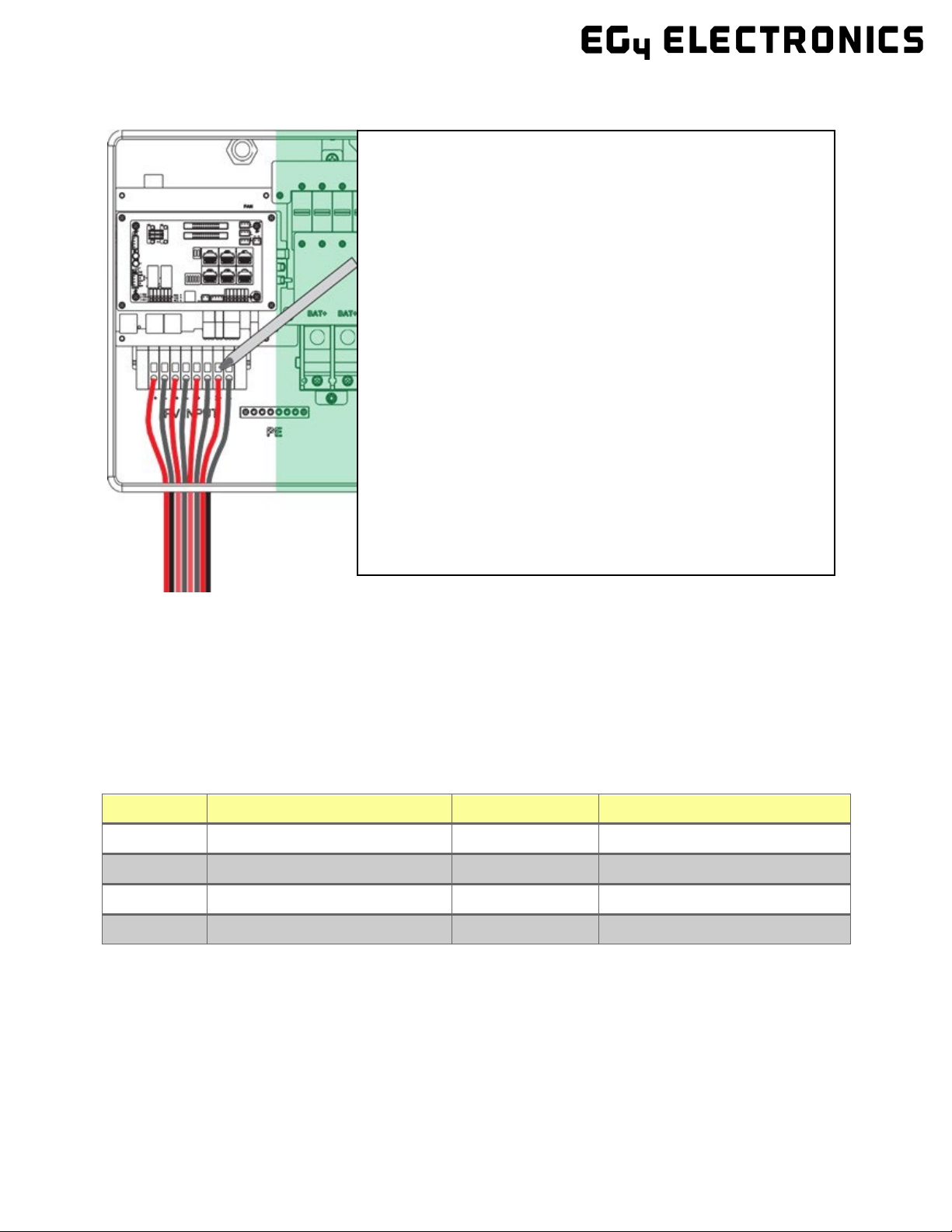
4.5.2 Battery Power Cable Connection
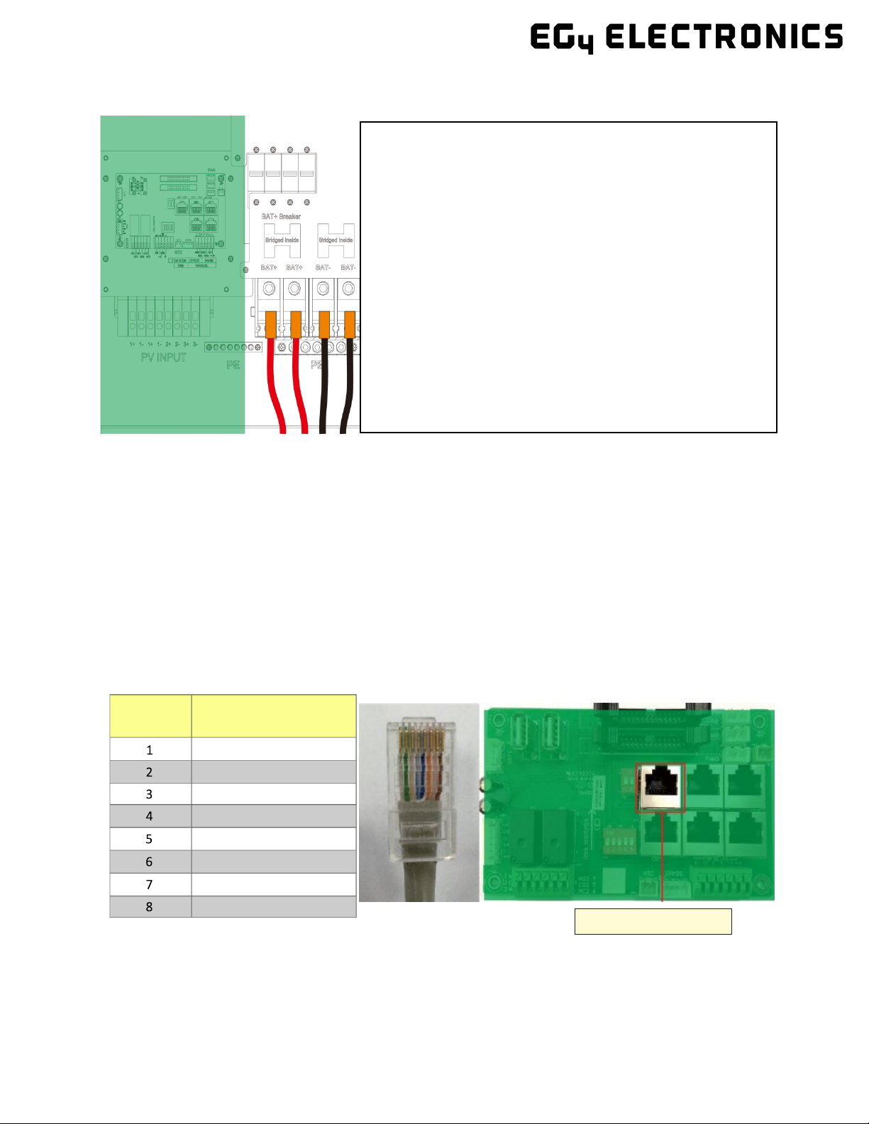
4.5.3 Battery Communication Cable Connection
1. Use the included battery communication cable to connect the battery to the inverter and choose
‘Lithium’ as the battery type*. Please select the ‘Lead-Acid’ setting if the lithium battery cannot
communicate with the inverter. The battery communication port on the inverter is an RJ45
socket with the pinout for the RJ45 plug shown on the following image.
Users can make the communication cable according to the inverter pin description below and the
correct pinout of the communication port on the battery. The inverter supports both CAN and
RS485 communication.
*For inter-battery communication and battery bank setup with EG4® batteries, please refer to the
respective battery manual.
Continued on next page…
Pin
Description
Pin 1 2 3 4 5 6 7
NC
GND
NC
BAT CAN H
BAT CAN L
NC
BAT
RS485 A
BAT RS485 B
Battery CAN & RS485
1. Place all breakers in the OFF position before connect-
ing or disconnecting wires. Ensure that there is no volt-
age present with a voltmeter.
2. Strip 5/8–13/16 in. (15-20 mm) insulation from the
cable end.
3. Route the battery power cable, connecting positive to
BAT +, and negative to BAT -.
4. Secure the conduit fitting to the enclosure using the
counter nut.
5. Fasten battery positive and negative cables to the me-
chanical terminals according to the markings with an
M8 hex wrench.

19
2. After connecting the battery power
and communication cables, enter
the ‘Advanced’ settings to choose
the battery type and brand. When
prompted, enter “00000” as the
password to enter settings menu.
Note: For communication with EG4 bat-
teries, select “Lithium” under ‘Battery
type’ and then select “0: EG4” under ‘Lith-
ium Brand’.
For more information on configuring
charge/discharge settings, refer to Section
11.3.2 – Setting Parameters
For Lithium Battery:
Please be sure that the lithium battery
being used is compatible with the inverter.
EG4® strongly recommends using closed-
loop communications between your bat-
tery and inverter. Please contact your dis-
tributor or support@eg4electronics.com for
an updated battery closed-loop communi-
cations list.
If you are using multiple battery modules with the inverter, the inverter communication cable must be
connected to the master battery. Please check with your battery supplier for battery master and slave
settings.
For Lead-Acid Battery:
The temperature sensor for lead-acid batteries is optional.
There are three stages for lead-acid battery charging. For charge/discharge related parameters, please
check the ‘Charge’ and ‘Discharge’ settings in Section 11.3.2 - Setting Parameters.
Other manuals for 18KPV
1
Table of contents
Other EG4 Inverter manuals


Popular Inverter manuals by other brands

Westerbeke
Westerbeke 5.5 BCD-614 specification

Toshiba
Toshiba Q7 Flow Installation and operation manual

Mitsubishi
Mitsubishi FR-E 500 instruction manual

Waeco
Waeco pocketpower SI102 operating manual

Larson Electronics
Larson Electronics SPEPSN-HRN-PA Instruction guide

Honeywell
Honeywell 10 kW owner's manual


