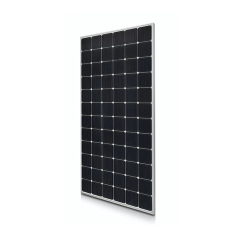
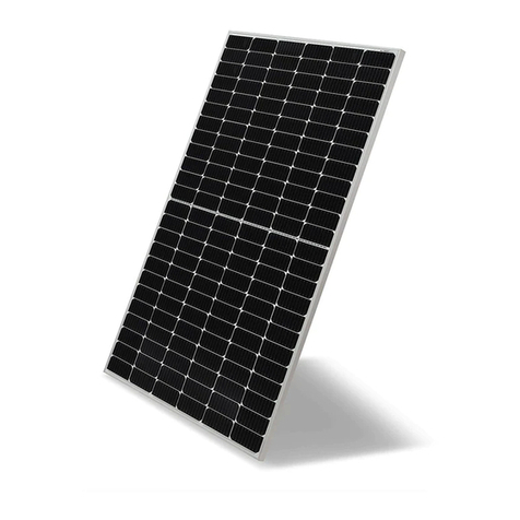
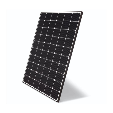
LG LG N3K-V6 Series User manual

Please read this manual carefully before operating
your set and retain it for future reference.
N-TYPE MODELS
LGXXXN3C(W)-V6
LGXXXN3K-V6
www.lgsolarusa.com
Installation manual
PV Solar
MODULE

TABLEOF CONTENTS
SAFETY 03
BEFORE &AFTER INSTALLATION 05
Before Installation 05
After Installation 05
ELECTRICAL INSTALLATION 06
Danger 06
Electrical Connections 06
Diodes 06
Series Connection 06
Parallel Connection 07
General Wiring 07
Earth Grounding 07
MECHANICAL INSTALLATION 08
Module Mounting 08
Site Consideration 08
Mounting Methods 08
DISCLAIMER OF LIABILITY / DISPOSAL 10
TRANSPORTING AND STORAGE 10
REVISIONS TABLE 10
PRODUCT SPECIFICATIONS 11
Electrical & Mechanical Properties 11
Dimensions of Modules 13

SAFETY
The instructionsrelated to the safetyindicatedin the
following are for preventing unexpected danger or
damage in advance by safely and exactly using the product.
DANGER
WARNING
CAUTION
Non-compliance of the instructionsmay immediately
causeseriousinjury or death.
Non-compliance of the instructionsmay cause deathor
seriousinjuryto the user.
Non-compliance of the instructionsmay cause injury or
property damage to the user.
DANGER
Do not contactelectricallyactive p
arts of the panel, suchas terminal
s, without appropriate safetygear.
Contact may result in lethal spark
or electricshock.
Do not use or install if the module
is broken or torn. Failure to compl
y may result in electricshock.
WARNING
Perform all work in dry conditions
anduseonly dry tools. Do
not handlewet panels without app
ropriate protection equipment. Fail
ure to complymay result in accide
nt or death.
Damaged modules must be treat
ed with safetyprotectionequipme
nt. Failure to complymay result i
n serious bodily injuryor death.
No electrical parts like cables are
located after installation between
laminateand mountingstructure.
Do Not reconnector repair junct
ion box cable. It may occur spar
k or electricshock.
Do not bending junctionbox's ca
ble. Whileunder stress, it may o
ccur moduledamage. Cable ben
ding radiusshouldbe more than
4 times the cablediameter, at lea
st.
CAUTION
Use proper equipment, connector
s, wires and buttresses for the ins
tallationof the module.Failure to
complymay result in product da
mage, product failure or bodily inj
ury.
Packagedmodulesshouldbe
stored in a cool and dry plase.
The modulepackaging is not
water-weatherproof.
If stored for a long time in an un
controlled environment, it can ca
use discoloration problems of so
lar module.
Do not approach the damaged or
broken moduleunless you are an
authorized or qualifiedexpert. Fai
lure to complymay result in serio
us bodily injuryor death.
03

Do not touch the glass surfaceor
frame of the solar module after in
stallationof the module.It may re
sult in injury or death.
Heavy objects must be kept off of
the solar module.
Do not stand on or step on the m
odule. Do not drop the module.F
ailure to complymay result in pro
duct damage, product failure or b
odily injury.
Do not scratch the coating
surface of the frame.
Scratchesmay decrease the total
solar output dueto corrosionof th
e frame.
Do not artificially concentrates
unlight on the solar modulesur
face. Failure to complymay re
sult in product damage or failur
e.
Do not apply a shockto the j
unctionbox of the module or
pull the cable. Do not remove the
labels attached to the module.
Failure to complymay result in
damage of the product.
If the installing moduleson curved surface, (e. g. arch ty
pe), as shown in the below picture, do not forcefully mo
dify the module in the installationwhen connecting it wi
th the structure. Only install the modulein the place wh
ere the structure for the panelshasbeen properly set u
p.An improper structure may cause deformation of the
panels. Panelsmay also be damaged byunapproved in
stallation methodssuch as the use of a
Module
Installing structure
(bent type)
Module Installi
ng structure (Stral
ght type)
Product D
eformation Occurrence
of space
Partial shadow must be removed
from solar module because it can
cause severe problems of solar
module.
Holes in the frame or glass of
the modulemay decrease the
strength of the frame or break the
glass.
Installation during rain, heavy wi
nd or snowy day may result in b
odily injury or death.
crane. 4

BEFORE &AFTER INSTALLATION
Before Installation
5
Pleasecarefully read this manual before installation.
Solar module installation and maintenancemust be
performed by qualifiedand authorized installer.
All installation instructions shouldbe read and
understood before performing any installation.
Do not touch the solar module with bare hands.
It may result in a burn or injury.
Do not disassemble the solar module.
After installation or repair, check that the solar module
are operating properly.
In the event that the currently used solar module or p
arts havebeen replaced the newly replacedmodule a
nd parts must have the same model nameand parts a
s the previouslyinstalled solar module.
In the case of a different modelname replacement,
After Installation
Plug in the connector tightly and ensure that the wiring
properly works.
electrical characteristic model within 80% of the maximum Conduct periodic inspectionof the panelsfor damage
to front glass, back sheet, frame, junction box, or
external electrical connections.
Check electrical connectionsfor loose connections
and corrosion.
PV panels canoperate effectively without ever being washed,
although removal of dirt from the front glass can increase
output.
Water, ethanol or a conventional glass cleanserwith a
micro-fiber cloth can be used for regular washing or ri
nsing of the front glassto remove dust, dirt or other de
posits.
Do not use ground water containingcalciumcarbonate
componentswhen cleaningglass.
Aggressive and abrasive cleansers or chemicals such
as alkali chemicals including ammonia based solution
shouldnot be used on cleaning the module.
Always keepthe back surface of the panel free from a
ny foreign objects or structural elements which couldc
ome into contactwith the panel, especiallywhen the p
anel is under mechanicalload.
Deposits of foreign material on the frame surfacecan
be cleaned by using a wet spongeor cloth and dried i
nair or by using a cleanchamois.
Perform the wiring work by connecting the connector
and wires to the stand away from the roof or ground.
Do not useany kind of oil or lubricant on the module's
any parts, It can defect the PV Module.
voltage of the system.
Do not let anyone approach the solar modulewhohas lit
tle knowledgeof solar modulesor on the measuresto ta
ke when solar modules are damaged in order to avoid th
e risk of injuryor electricalshock.
Secure all necessary permits and licensesto install
the solar modules.
Do not locate the solar modulehorizontally, as this may
causedirt or white efflorescence(glass deformation).
Panels are not intended for useindoors or on moving
vehicles of any kind.
Industry standardrated specifications are made at
conditionsof 1000W/m2irradianceand25°C (77°F)
solar cell temperature. Colder temperatures may su
bstantially increase voltage and power.
Keep the solar moduleand system away from children
at all times.
Keep the modulepacked in the cartonuntil the time of
installation.
Keep flammablegasses away from the installation
site.
Do not work alone. Pleasework as part of a team of
two or more people.
Safety harness use isstrongly recommended for
installation.
Be careful not to damage thecablewhen using a tool
such as a knife to remove the cable tie that fixes the j
unctionbox cable.
Partial shadowing may substantially reduce paneland
system output and may be the reason for the damage
of solar module.
Care must be takento avoid low tilt angles which may
causedirt to buildup on the glassagainst the frame ed
ge.
Dirt build-up on the surface of the panel may cause
active solar cells to be shadedand electricalperfor
mance to be impaired.
it is possibleto replace an equivalent or higher

ELECTRICAL INSTALLATION
Danger
Avoid all electrical hazards when installing, wiring,
operatingand maintainingall panels.
Do not connectpanels that have different electrical
propertiesor physical configurations in the same sy
stem.
Match the polaritiesof cablesand terminalswhen ma
king the connections; failure to do so may result in da
mage to the panel.
The rating of the over-current device shall not exceed
the maximum series fuse rating marked on the name
plate.
The panel containsfactoryinstalledbypass diodes
locatedinsidethe junctionbox.
Wheninstallingthe system, it is recommended to
install a lightningrod to protect the system.
The induced overvoltage by lightning can cause the
system damage, you should design conductor loop
connectionas minimum as possible.
The junctionbox shouldnot be opened. Openingthe
junctionbox will void the warranty.
Panels with a suspectedelectricalproblem shouldbe
returned to LGElectronics for inspectionand possible
repair or replacementas per the warranty conditions p
rovided by LG Electronics.
Electrical Connections
Shock hazard may occur near the solar modules
electrical connections.
Modulesmay be connectedin series and/or parallel
to achieve thedesired electricaloutput as long as it i
s within the guidelines on the product specification s
heet.
Pleaseuseonly the same type of modules in a
combinedsourcecircuit.
Do not disconnect the module under when it isop
erating. Shock hazard may occur near the solar m
odules connectionmeans.
Whenthe moduleinstallingin series or in parallel
(e.g. using for extension cables,etc.), the
connectorof each moduleshouldbe the same
products. (mated with its original female or male
connector of the same supplier)
Diodes
All LGmodulesare equipped with factoryinstalledb
ypass diodes. The factory-installed diodes provide p
roper circuit protectionfor the module from unexpec
ted shadows.
Series Connection
The solar modules may be wired in series to produce
the desired voltage output.
The current of each moduleconnected in series
shouldbe the same.
The maximum PV system voltage for that circuit shall
be calculated as the sum of the rated open-circuit
voltage of the series-connected PV modules corrected
for the lowest expected ambient temperature. For the
LG Mono crystalline modules,the rated open-circuit
voltage shall bemultiplied by the correction factor
provided inNEC Table 690.7. The maximum current
of Photovoltaic Source Circuit Currents shall be the
rated short-circuit current of the series-connected
module multiplied by 125 percent inaccordance with
NEC article 690.8.
Diode specification and configuration
+
6
-
1
D 1 D 2 D3
2 3 4
UKTH3045-12
IF(AV) 30A
VF (max) 0.8V
VRRM 45V
Tj (max) 200°C
RTH 0.8°C/W

Parallel Connection
The solar modulesmay be combinedin parallel to
produce the desired current output.
When modules are combined in parallel, the total
current is equalto the sum of currents from each
module.
The voltage of each module connectedin parallel
shouldbe the same.
Whenconnecting plural strings of modulesin parallele
very series string or solar modulemust be fused priort
o combiningwith other strings.
Abide with all applicablefederal, state, and local codes
for additional fusing requirementsand limitationson the
maximum number of solar modulesin parallel.
Maximum series fuse rating is refer to “Product
Specifications; page11”.
Parallel configuration is not limited if proper measures
are taken to block the reverse current flow, e.g. fuses f
or the protection of the module and cables from over-
current for prevention of unbalanced string voltage.
LG Electronics recommends to take blocking diode
for prevention of unbalanced string voltage.
The reverse current flow in the string may be caused by
amoduleshortcircuit,incorrectwiring,shadow,etc.
Blocking diodes must have :
1) VRRM(Repetitive Peak Reverse Voltage) :
1.5times of maximum system voltage
2) IF (Average Forward Current) :
2 times of Isc (PV module short circuit current)
※It is selected in consideration of the thermal
characteristics of the diode, and it is recommended
to use acomponent of 30mA or less for IRRM
(Repetitive Peak Reverse Current, max).
Amultiplying factoris requiredfor increased output
of the PV modules.Under normal conditions, a PV
moduleis likely to experience conditionsthat produce
more current and/or voltage than reported at standard
test conditions. The requirements of the National Elect
rical Code (NEC) in Article 690 shall be followedto ad
dress theseincreased outputs.
The values of Isc and Voc marked on this PV module
shouldbe multiplied by a factor of 125% when determ
ining component voltage ratings, conductor ampacitie
s, fuse sizes, and size of controls to the PV output.
Depending on national directives, additional safetyfact
ors might be applicable for over current protection.
General Wiring
LGElectronicsrecommendsthatallwiring bedouble
insulatedwitha minimumratingof 90°C(194°F).
AllWiringshoulduseaflexiblecopper(Cu) conductor.
Theminimumsizeshouldbedeterminedbythe
applicablecodes.
LGElectronicsrecommendsasizenosmaller than
12AWG.. 7
Earth Grounding
All work must be conducted in conformancewith all
Federal, State, and local codesand standards.
Groundingworks should be performed by an authoriz
ed installer for the safety and maintenance of the syst
em in accordance with all national, state and local ele
ctrical codes and regulations and standards.
Specific information on the solar moduledimensions a
nd locationof grounding holes is provided in “Product S
pecifications”.
One M4 stainless steel bolt, onenut, one springwash
er, two flat washers, one cup washer, one star washe
r and 12 AWGCu wires are recommended per mount
ing hole.
Where common grounding hardware (nut, bolts,washe
rs) is used to attacha listed grounding device, the attac
hment must be made in conformancewith the groundi
ng device manufacturer’s instructions.
All hardware should be consist of corrosionresistant
material such as stainless steel.
There is an earth hole on the edge of the module f
rame. Using this hole, an earth conductor and the
solar moduleframemay be recommended to be c
onnectedand earthed as the below drawing.
All screws andnuts shall be tightenedto a torque of
4~5 N∙m.
A modulewith exposed conductive parts is
consideredtobeincompliancewithCSA/UL61730only
wheniselectricallygroundedinaccordancewith the
instructionspresentedbelowandtherequirementsof
theNationalElectricalCode.
Theinstallationinstructionsshallinclude:
1.Detailsforwiring shallcomplytheNEC Article690.
2.Detailsforthegroundingmethodofthe frameof
arraysshallcomply with theNEC Article 250.
3.CNLmodelinstructionmanualsshallalsoinclude
a statementthatinstallationshallbeinaccordance
with CSA C22.1, SafetyStandard for Electrical
Installations,CanadianElectricalCode,Part1.
Bondingpointsto ground shouldbe tight, secureand free fro
m corrosion. (Maintenance is especially important in areas wit
hhigh levels of salt in the atmosphere, such as coastal areas
and the surroundingseas.)
Module frame
Bolt
Flat washer
Star washer
Cup washer
Grounding wire
Flat washer Spr
ing washer
Nut

MECHANICAL INSTALLATION
ModuleMounting
The LG Electronics’ (LGE) LimitedWarranty for solar mo
dules is contingent upon modules being mounted in acco
rdance with the requirements described in this section.
Any module without a frame (laminate) shall not be
considered to comply with the requirements of CSA/
UL61703 unless the module with hardware that has
been tested and evaluated with the module under this
standard or by a field inspection certifying that the
installed module complies with the requirements of
CSA/UL61730.
The solar modules are in Application Class A and have t
he Safety Class II. Therefore they can be operated in sys
tems with 120V DC and higher. General access is notre
stricted.
We recommend to use mounting device(bolt, nut, wa
sher) made by corrosion resistant material like stainl
ess steel.
Mounting
Rails
Use corrosionresistant material mounting rails and
hardware.
Use appropriate boltedconnectionsas per
manufacturer’s instructions.
No electrical parts like cablesare locatedafter installa
tion between laminate and mountingstructure.
8
Site Consideration
LGE solar modules shouldbe mounted in a locationthat
meets the following requirements.
Module Operating Temperature
Temperature range : -40°C ~ 85°C (-40°F ~ 185°F)
The operating ambient temperatureof thesedevices
may exceed 40℃at full load for all wire sizes if is det
ermined suitable in the field use application.
Excluded Operating Environments
The solar modulesfrom LGElectronics can not be op
erated in a location where they couldcome in direct co
ntact with salt water or ammonia.
Do not use moduleto replace(or partly replace)roofs
and walls of living places.
Module Strength(BasicLoad) ; CSA/UL61730
Ymis a safetyfactor of 1.5
Detail of mounting distance is below.
*This mounting method is by using frame bolt holes.
*The mounting rails must run perpendicularly to the module
long side.
MountingMethods
General Information
Select the appropriate orientationto maximize sunlight
exposure.
The module generates maximum output power when it
faces the sun directly. The tilt angle of the modules sho
uld be selectedto optimize seasonaland sunlight
-basedperformance in the installationplace.
Module shouldnot be mountedor storedin a way that
the front/topglass facesdownward in order to prevent
water from entering the junction box, which couldcaus
e a safetyhazard.
Clearance between the solar module frames and stru
ctures such as roofs or ground is requiredto prevent
wiring damage andto allowair to circulate behindth
e solar module.The recommended standoff height is
a minimum of 100mm.
Wheninstalled on a roof, the solar module must be mo
unted over a fire-resistant roof covering rated for the a
pplication. The fire resistanceof the solar moduleis cla
ss C after ANSI/UL790 Edition 2004.
The solar moduleis only IEC listedfor use when its
factory frame is fully intact.
Removal or alteration must be done by an authorized
and qualifiedindividual.
Creating additional mountingholes may damage the
solar moduleand reducethe strength of the frame.
Werecommend a 6mmgap between moduleframes
to avoid tension from thermal expansion.
132
Cell
(half
-
cut)
228mm
No
. of
Cell
Force
Direction
Desig
nLoad :
A
Test Load :
B (B = A x
Ym)
132Cell
(half-cut
)
Front
Side
3600 Pascal 5400 Pascal
Rear Side 2650 Pascal 4000 Pascal
Shadow
LGE solar module should be installed in a proper site that
there is no shadowing affectedby building,
chimney, tree, andneighboring module,etc.

The fire rating of this module is valid only when
mounted in the manner specified in the mechanical
mounting instructions.
The module is considered to be in compliance with
CSA/UL61730 only when the module inmounted inthe
manner specified by the mounting instructions below.
The solar module may be mountedby using the
following methods:(*Torque:8~12N∙m)
LG modules(Fire performance: Type 1 or 2) shall be
mountedwith rackingand mounting productscertified
and listed for system fire classrating in accordance
with CSA/UL61730.
It is recommended to check with local authorities
for fire safetyguidelinesand requirementsfor any
buildingor structureon to which the panelswill be
installed.
When installing modules in heavy snow areas,
it is recommended to be taken an appropriate
countermeasure to prevent possible damages to the
lower side frame by slipping snow.
We recommend to use corrosion resistant material
according to standard CSA/UL61730 for these
supporting part. (A snow guard should be installed in
accordance with the manufacturer’s instructions.)
Solar module
Supportingpart
Roof
Mounting by using frame bolts holes
Secure the solar module to the structure by using the
factorymountingholes.
Four M8 stainless steel bolts, four nuts, four spring
washers, andeight flat washers are recommended
per solar module.
The modulemay be fastened to a supportby using
both the outer andinner bolt holes of the frame.
Each module should be securelyfastened at a
minimum4 points on two opposite sides.
09
→ We recommend more than 40x40mm mounting rails.
Module frame
Nut
Spring washer Flat
washer
Mounting Rail Flat
washer
Bolt
* Mounting Rails Material : Aluminum, Stainless steel, etc.
Specific information on the solar module dimensions
and locationof mountingholes is provided in ‘Product
Specifications’.
Tighten the bolt securelyby using the combination. Place
the spring washer between the Flat washer and Nut.

This installationmanual(Version1) replacesall previous versionsexcept electricaland mechanicalcharacteristics.
For electrical and Mechanicalcharacteristics of each model, please refer to the Datasheet for each model.
DISCLAIMER OF LIABILITY / DISPOSAL
Disclaimer of Liability
By beginningto installationprocess, the installer hasto read and completelyunderstand this Installation Manual.
If installer hadany questions regardingthis installationmanual,theinstaller would have contacted LG with any
questions or concerns.
By installingan LG Solar module,I discharge, and covenantnot to sueLG, its affiliatedcompanies,
successors,
or assigns,its administrators, directors, agents, officers, volunteer and employees, other participantsin any activity
connectedto installation, operation, or service of LG Solar Modules, and if applicable, from all liabilities, claims,
demands, losses, or damageson my account causedor alleged to be caused in whole or in part by the negligence
of the LG its affiliated companies, successors, orassigns, its administrators, directors, officers, volunteer
and employees.
Disposal
Please contact your local disposal center or Dealer/Distributor.
TRANSPORTINGAND STORAGE
Do not loosen the banding, when the moduleis transportedby truck,ship and etc. I
n case of loosebanding, the modulewill be shaken, which may cause damage.
Do not stack on more than onepallet. Maximum height is two pallets. Severe stackingcan cause stressto the
moduleand may cause product damage.
Do not transport only one side of the module when transporting the module.Damage to the frame or cable may occur.
Packagedmodules shouldbe storedin a cool and dry plase. The modulepackaging is not water-weatherproof. I
f stored for a long timein an uncontrolledenvironment, it cancausediscolorationproblems of solar module.
REVISIONS TABLE
10
Date Version Description of change Remark
2021.01.26 1.0 (1stedition) Publish Installation Manual

PRODUCT SPECIFICATIONS
Rated electricalcharacteristic except power rating within -0/+3 percent are within 5 percent of measured.
Values at Standard Test Condition(STC) : Irradiance 1000W/m2, Cell temp. 25℃, 1.5AM
Note) MC4 formal name :PV-KST4 / 6II-UR,PV-KBT4 / 6II-UR
→ Plus (+) Connector : Male MC4 coupler (PV-KST4/6II-UR)
→ Negative (-) Connector: Female MC4 coupler (PV-KBT4/6II-UR)
Note) The Typical change in module efficiencyat 200W/m2in relation to 1000W/m2is -2.0% / ‘N3K-V6’ is -3.0%
◇Female and male cable couplers ◇
Female cable coupler
*NMOT (Nominal Module Operating Temperature) : Irradiance 800W/m2, ambient temperature 20℃, wind speed 1m/s
Temperature Characteristics
* See more information >> http://www.multi-contact.com/ or http://en.ukt-sz.com/
Electrical Properties(NMOT*)
Ø A
Ø A
Male cable coupler
“Max. No. of modules in series” is considering 125% of Voc. Actual number of connections
should be selected according to the installation site conditions and local code.
Model
LGXXXN3C(W)-V6 LGXXXN3K-V6
N
MOT [ °C ]42±3 42±3
Pmax
[%/°C] -0.33 -0.33
Voc
[%/°C] -0.26 -0.26
Isc
[%/°C] 0.04 0.04
Model LGXXXN3C(W)-V6 LGXXXN3K-V6
395 400 405 410 415 390 395 400 405 410
Maximum Power (Pmax) [W] 298 302 305 309 313 294 298 302 306 309
MPP Voltage (Vmpp) [V] 34.2 34.5 34.9 35.3 35.7 34.3 34.6 35.0 35.4 35.8
MPP Current (Impp) [A] 8.72 8.73 8.75 8.76 8.77 8.59 8.60 8.62 8.64 8.64
Open Circuit Voltage (Voc) [V] 42.0 42.2 42.4 42.6 42.8 42.4 42.5 42.6 42.7 42.8
Short Circuit Current (Isc) [A] 9.10 9.14 9.18 9.21 9.25 8.92 8.96 8.99 9.02 9.05
Model
C
able Cross Section ØA(Cable outer diameter) Rated current
MC4
4mm²
5.5 ~ 9mm 30A
12AWG
Note) Max. Bifaciality Coefficient of Power : N3C(W)-V6 0.04 / N3K-V6 0.06
Max. Bifaciality Coefficient of Current : N3C(W)-V6 0.05 / N3K-V6 0.07
Max. Bifaciality Coefficient of Voltage : N3C(W)-V6 0.88 / N3K-V6 0.88
11
Note) For information about the electrical ratings for both front and back surfaces (Bifaciality Coefficient)
and the expected contribution from ground reflected irradiance along with ground cover and installation height above ground
that reflected irradiance, please refer to the sales talk material and datasheet.
Electrical Properties Mechanical Properties
Module
Series
Model Name
Pmax
at STC
Pmax
at
Bifi100
Pmax
at
Bifi200
Power
Tolerance
Voc at
STC
Isc at
STC
Vmpp at
STC
Impp at
STC
Max.
No of
Module
In series
Max.
Series
Fuse
Rating
Max.
System
Voltage
Connector
Length
Width
Height
Weight
W W W % V A V A A V mm mm mm kg
LGXXXN3C(W)-V6
LG395N3C(W)-V6 395 395.8 396.6 0~3% 44.6
11.30
36.3 10.89 17 20 1000 MC4 1880
1042
40 19.7
LG400N3C(W)-V6 400 400.8 401.6 0~3%
44.8
11.35
36.7 10.90 17 20 1000 MC4 1880
1042
40 19.7
LG405N3C(W)-V6 405 405.8 406.6 0~3%
45.0
11.40
37.1 10.92 17 20 1000 MC4 1880
1042
40 19.7
LG410N3C(W)-V6 410 410.8 411.6 0~3%
45.2
11.44
37.5 10.94 17 20 1000 MC4 1880
1042
40 19.7
LG415N3C(W)-V6 415 415.8 416.7 0~3%
45.4
11.49
37.9 10.95 17 20 1000 MC4 1880
1042
40 19.7
LGXXXN3K-V6
LG390N3K-V6 390 391.6 393.1 0~3%
45.0
11.08
36.4 10.72 17 20 1000 MC4 1880
1042
40 19.7
LG395N3K-V6 395 396.6 398.2 0~3%
45.1
11.12
36.8 10.74 17 20 1000 MC4 1880
1042
40 19.7
LG400N3K-V6 400 401.6 403.2 0~3%
45.2
11.16
37.2 10.76 17 20 1000 MC4 1880
1042
40 19.7
LG405N3K-V6 405 406.6 408.2 0~3%
45.3
11.20
37.6 10.78 17 20 1000 MC4 1880
1042
40 19.7
LG410N3K-V6 410 411.6 413.3 0~3%
45.4
11.24
38.0 10.79 17 20 1000 MC4 1880
1042
40 19.7

Dimensions of Modules
Unit: mm / in.
LGXXXN3C(W)-V6 / LGXXXN3K-V6
Frame Cross section
Long Frame Short Frame
12

LG Electronics U.S.A Inc.
2000 Millbrook Dr., Lincolnshire, IL 60069
Contact :lg.solar@lge.com
http://www.lgsolarusa.com
This document is subject to change without notice.
LG, LG logo and Life's Good are trademarks of LG Electronics, Inc. worldwide. Trademarks and i
ntellectual properties of LG Electronics, Inc. are protected by international copyright laws.

228
890~990

Note) All mechanical installation methods and bolting method in this appendix were not tested by CSA or 3rd party.
It is evaluated by LG internal test.


This manual suits for next models
11
Table of contents
Other LG Inverter manuals

LG
LG N2W-E6 Series User manual

LG
LG ACAH020HETB Installation instructions

LG
LG LG N1K-N6 Series User manual

LG
LG LG S1C-G3 Series User manual

LG
LG N2W-L5 Series User manual

LG
LG N1T-V Series User manual

LG
LG A1 Series User manual

LG
LG LG340N1C-A5 User manual

LG
LG KM113.27UU User manual

LG
LG RESU16H Prime User manual
Popular Inverter manuals by other brands

Solplanet
Solplanet ASW S Series user manual

Extel
Extel NOMAD 13 Installation and user guide

PAW
PAW SolarBloC midi Basic DN 20 Installation and commissioning instructions

Growatt
Growatt WIT 50-100K-HU quick guide

Fimer
Fimer UNO-DM-4.0-TL-PLUS-Q Quick installation guide

Schumacher Electric
Schumacher Electric PID-410 owner's manual