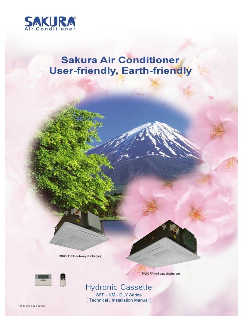
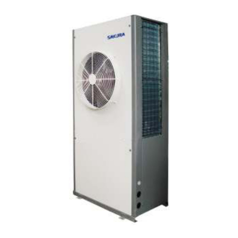
Sakura SFP KM EC Series Technical document

Sakura Air Conditioner
User-friendly, Earth-friendly
Sakura Air Conditioner
User-friendly, Earth-friendly
Ref, S- 160 / 03 / 10 (H)
Hydronic Cassette
SFP - KM - EC Series
( Technical / Installation Manual )
Panel (Type-A) 680×680 Panel (Type-A) 680×1240
Panel (Type-B) 680×680 Panel (Type-B) 830×830 Panel (Type-B) 680×1240

The EC motor used in the VAV fan coil is a brushless direct current (DC) motor that connects directly
to the 230V AC mains supply. The AC-to-DC conversion and motor commutation are integrated within
the motor body and this ensures increased efficiency which provides lower running temperature and
higher life expectancy than a traditional motor. EC microprocessor-based commutation also provides
other features including alarm outputs and speed monitoring.
EC motors typically boost motor efficiency from 45 to 80 per cent and therefore achieve lower specific
fan power. However, while higher efficiency motors are available for terminal units incorporating fans,
the forward curved fan impeller is not particularly efficient so the overall motor and fan efficiency is 37
per cent for EC and 21 per cent for AC (see table 1).
Table 1
Motor
type Air flow Volts in Current Power Power
factor Motor
Volts
Specific
fan
power
Apparent
power
l/s V A W V W/(l/s) VA
AC 320 230 0.68 135 0.85 169
(AC out) 0.422 156.4
EC 321 230 0.48 68 0.61 5.8 (DC) 0.212 110.4
An AC motor’s speed is controlled by voltage reduction and tapped transformers are normally used to
achieve this. However, this voltage reduction reduces the motor efficiency. EC motors, on the other
hand, use a low voltage reference signal to provide a command to the commutation to change the
speed. The control signal can be either 0 – 5VDC analogue, and motor efficiency is maintained from
high speed down to low speed.
Essentially, the EC motor is more efficient than the AC motor because:
•It does not need to induce a current in the rotor.
•The EC motor has a simpler winding which results in reduced copper losses losing less heat
to the air. At 320l/s, AC motors will increase the air temperature by 0.345°C compared with
0.174°C for EC motors.
•The specific fan power of EC motors is lower and exceeds the requirements of the latest
Building Regulations.
As standard, the EC motor has an input terminal for a 0 to 5Vdc signal from a building management
system (BMS) controller to vary the set volume on the fan in relation to the room temperature at
minimal additional cost to the BMS package.
1
SAKURA - Total Air Conditioning Solution

2
ENERGY SAVING EC FAN COIL UNITS
We, SAKURA have incorporated an energy efficient EC fan option for most of the units in the range that
significantly exceeds the current Part L Specific Fan Power (SPL) requirement of 0.8 W/l/s.
The fan coils are offered with a range of accurate and cost effective speed control options providing a
flexible and user-friendly facility to have full controllability with standard analogue or DDC controls. The
power conversion from AC to DC is incorporated within the motor and fan assembly and allows a normal
mains 230VAC supply to be used.
EC MOTOR DESCRIPTION
Electronically Commutated Motors (EC Motors) are a brushless DC motor and have no mechanical
commutator. They use microprocessor technology to control the level of current through the windings.
This electronic operation offers a significant advantage over traditional AC motors namely; high efficiency,
energy savings, continuously variable speed control, compact design, long life and direct connection to AC
mains.
FEATURES & BENEFITS
AC MAINS CONNECTION
The EC Fan Coil Units connect to the AC mains in the same way as the AC motor powered units.
They include a rectifier to convert AC to DC current. Harmonic filtration is also included as required to meet
current regulations (‘Harmonics to Mains Supply’ regulation in EN 61000-3-2), simply connect the unit to
the mains bus bar or local fused spur as usual.
REDUCED POWER CONSUMPTION
Typically, when a medium sized Fan Coil Unit is directly compared AC vs. DC there is a significant power
saving. The DC unit had a harmonic filter fitted as recommended to comply with the regulations.
On a medium speed setting the following measurements were recorded:
The 57% reduction demonstrates the saving measured in Watts. Expressed as VA, a saving of 33% would
be seen. A further 25-30% can be saved by employing a set back speed when duty demands are reduced.
A report from a leading fan and motor company states that a significant improvement in energy
reduction is achieved with the use of EC fans. Taking a typical duty of 190 l/s with an external
resistance of 30 Pa the EC solution provides a power saving of 91W and reduces the Specific Fan
Power (SFP) from 0.72 to 0.25 W/l/s. Fan coils are often used in office applications where they
operate 12 hours a day, 3120 hours per year. Using the above energy saving of 91W, there is an
annual saving of 384 kWh and 122kg of CO2.
A typical installation of 500 units will save 61 tonnes of CO2 per year.
REDUCED MOTOR HEAT PICK-UP
Due to the lower energy requirement and higher efficiency of EC motors the heat pick-up is significantly
reduced. This reduced heat gain can be incorporated at the design stage to reduce chiller, pumps and pipe
work sizes. The above medium sized unit demonstrates a saving of 120W through reduced motor heat
pick-up.
ATL236 AC DC REDUCTION
W 210 90 57%
VA 210 140 33%
SAKURA - Total Air Conditioning Solution

3
LIFE EXPECTANCY
Due to the EC motors running cold and not being subject to thermal stress the life expectancy is almost
twice that of an AC equivalent motor. A quality AC motor would have a life expectancy of approximately
50,000 hours, the EC versions have a life expectancy exceeding 80,000 hours, or over 20 years.
SELECTION OF FAN COILS WITH EC FANS
Testing of AC vs EC-DC fan coils back to back allowing for system resistances up to 30Pa external static
pressure, no difference in the air volume and resultant NR level was noted. Therefore, there is no
difference in the selection process between the two motor types.
SPEED CONTROL WITH EC
The fan speeds can be adjusted for Energy saving, low, medium and high. The fan runs at constant speed
at high, medium or low speed. Energy saving mode is suggested by the manufacture. The fan speed is
continuously changeable by 0-5VDC input signal. The input signal is calculated from the room temperature
and setting temperature. The Fan coil unit’s air flow volume can be changeable from 15%-100%. The
power consumption can be saved.
THE BUILDING REGULATIONS - PART L
With conventional AC motors, fan coils are typically running at a Specific Fan Power of around 0.5 - 0.8
W/l/s. Compliance with the maximum 0.8 W/l/s is dependent on the unit selection and the external static air
pressure in the system. EC - DC units with the high motor efficiency and lower power consumption
typically operate in the range 0.25 - 0.45 W/l/s. Being around 50% of the AC equivalent, the EC - DC fan
coil fully complies with the current Building Regulations and will greatly assist in the building energy
reduction calculations.
SUMMARY
In Summary EC Motors offer the following:
• Low energy consumption - up to 60% saving.
• Flexible speed control options - easy and accurate fan speed adjustment.
• Fully compliant to part L building regulations -half the Specific Fan Power of AC.
• High quality long life fan and motor -life expectancy nearly twice that of AC.
• Reduced motor heat pick-up - further energy saving on main plant chiller.
• No special electrical requirement - units are wired to normal AC 230V mains.
• EC fan coil performance as AC - simple selection process.
• Set back speed offers further savings of around 25-30% - total energy saving potential exceeds 70% (W)
or 50% kVA.
SAKURA - Total Air Conditioning Solution

DESCRIPTION OF THE UNIT
CASE
It is made of galvanized steel with inside and outside thermal insulation (closed cell NBR-
plastic foam 10 mm thick) and together with the specific flanges connects the channels to the
unit for the renewal of room air and/or to send it to an adjacent room.
FASTENING MOUNTING BRACKETS
Power steel mounting brackets clamps for attaching the unit to the ceiling.
FAN ASSEMBLY
The fan assembly mounted on anti-vibrating supports is extremely quiet. The single air inlet
radial fan is connected to a EC motor (standard) with single phase 230V/50Hz supply, class
B insulation.
HEAT EXCHANGER
It is made of copper tubes and aluminum fins bonded onto the tubes for maximum transfer
contact. The coils are with 2 rows for the 2-pipe and 4-pipe models.
All coils are provided with air bleed pipes and water drain valves, located respectively on the
highest and lowest point of the coil circulation. Air bleed valve and water drain valve are
positioned near the return air grill. It is very easy to operate them.
CONDENSATE COLLECTION TRAY
It is made of ABS with 5mm closed cell NBR-plastic foam.
AIR FILTER
Synthetic washable filter, easily removable
CONDENSATE PUMP
It is composed of a non return valve, a float and a pump with 650 mm. max. head.
ELECTRONIC BOX
The electronic box can be easily accessed and contains the terminal board for the electrical
connections. 1 PCB covers 2-pipe, 4-pipe, 2-pipe with EH as booster, 2-pipe with EH as
primary and 4-pipe with EH as booster for PCG/PCH-R
THREE OR TWO-WAY VALVES
3-way ON/OFF valve can be installed outside of case, which is easy to maintenance and
replace. 2 or 3-way valves are power with 1~ 230V 50Hz.
3-way modulating valve can be installed outside of case, which is power on 230V or 24VAC.
4
SAKURA - Total Air Conditioning Solution

CCAASSSSEETTTTEE FFAANN CCOOIILL UUNNIITTSS MMOODDEELL AASSSSIIGGNNMMEENNTTSS
S
K
S
(3) (4)
3V2
2V2
3MV2
(2)
R
W
R
(1)
V
P
V
(5)
EH
(6)
EC
EC
(6)
EH
(5)
V
P
V
(1)
R
W
R
(2)
3MV2
2V2
3V2
(4)(3)
S
K
S
51
85
SFP-KM4-
136
238
SFP-KM6-
170
102
((11)) 22--PPIIPPEE OORR 44 PPIIPPEE
V=2-pipe unit
P=4-pipe unit
((22))CCOONNTTRROOLL SSYYSSTTEEMM
R= With electronic PCB for functioning with infrared remote control
W=With pump control electronic PCB for functioning with a secondary wall-mounted
thermostat or 3-speed switch supplied separately
((33))PPOOWWEERR SSUUPPPPLLYY
S=230V/1PH/50HZ
K=220V/1PH/60HZ
((44))VVAALLVVEESS
3MV2= 3-way modulating valve for chilled water.
2V2 = ON/OFF 2 way valve for chilled water or hot water, which can be installed inside of unit
or outside of unit
3V2 = ON/OFF 3 way valve for chilled water or hot water, which can be installed outside of
unit
((55))EELLEECCTTRRIICCAALL HHEEAATTEERR
EH=Electrical heater
((66))MMOOTTOORR
EC= EC motor
5
SAKURA - Total Air Conditioning Solution

2-PIPE HYDRONIC CASSETTES
STANDARD SPECIFICATIONS SFP-KM4(6)-VS-EC SERIES
Model SFP-KM4-51-V SFP-KM4-85-V SFP-KM6-102-V SFP-KM6-170-V
Nominal airflow
(H / M / L) m3/ min 9.5/5.83/2.83 14.2/5.83/2.83 18.3/11.66/5.67 28.3/11.66/5.67
Air flow in energy saving
mode m3/ min from 2.83 to 9.5 from 2.83 to 14.2 from 5.67 to 18 from 5.67/28.3
Nominal cooling capacity
(H / M / L)* kW 3.4/2.3/1.5 4.72/2.32/1.6 5.8/4.34/2.5 8.45/4.34/2.5
Nominal sensible cooling
capacity (H / M / L) kW 2.57/1.768/1.2 3.57/1.974/1.43 4.53/3.57/2.0 6.49/3.52/1.98
Nominal cooling capacity in
energy saving mode kW from 1.5 to 2.57 from 1.6 to 4.72 from 2.5 to 4.53 from 2.5 to 8.45
Nominal heating capacity
(H / M / L)** kW 3.91/2.75/1.8 5.6/2.78/1.92 7.17/5.14/3 10.15/5.2/3
Nominal Heating capacity
in energy saving mode KW from 1.8 to 3.91 from 1.92 to 5.6 from 3 to 7.17 from 3 to 10.15
Electric Heater Capacity
(Optional) kW 1.0 2.0 3.0 3.0
Noise level (L / M / H) @
1m dB (A) 37/32/24 46/32/24 48/34/26 48/34/26
Power supply V / Ph /
Hz 230 / 1 / 50
No. of fan 1 1 2 2
Fan motor power (H/M/L) W 20/10.2/6.4 27.6/10.2/6.4 40/20.4/12.8 55.2/20.4/12.8
Fan motor running
current(H/M/L) A 0.174/0.1/0.068 0.265/0.1/0.068 0.348/0.2/0.136 0.53/0.2/0.136
Fan motor apparent
power(H/M/L) VA 40/23/15.64 60.95/23/15.64 80/46/31.28 121.9/46/31.28
Operation control Remote Control Handset & Wired Wall Pad
Water flow rate(H/M/L) L / h 601/406/265 834/424/282 1025/767/442 1470/767/441
Water pressure
drop(H/M/L) kPa 12.8/8.7/4.0 13.2/5.3/2.6 29.3/17.6/6.6 33.4/8.7/4.0
Water content L 1.247 1.558 2.216 2.769
Cond. drain connection I.D. mm (in) 19.05(3/4)
L mm 570 570 1,130 1,130
W mm 570 570 600 600
Dimensions
H mm 250 290 250 290
Gross weight kg 31 33 52 59
Panel dimension mm 680×680×28 680×1240×28
Connection method Socket(Threaded Female)
In mm (in) 19.05(3/4)
Water connection O
ut mm (in) 19.05(3/4)
09 V.1.2
*Cooling : 27oC db/19oC wb entering air temperature, 7oC entering water and 12oC leaving water temperature.
**Heating : 20oC db entering air temperature, 50oC entering water temperature with water flow rates same as for the cooling test.
***Heating capacity: 20oC db entering air temperature, 70oC entering water temperature, 60oC leaving water temperature.
6
SAKURA - Total Air Conditioning Solution

2-PIPE HYDRONIC CASSETTES
STANDARD SPECIFICATIONS SFP-KM4-VS-EC SERIES
Model SFP-KM4-136-V SFP-KM4-170-V
Nominal airflow (H / M / L) m3/ min 22.5/11.67/3.5 38.17/22.33/12.6
Air flow in energy saving mode m3/ min from 3.3 to 22.5 from 12 to 38.17
Nominal cooling capacity
(H / M / L )* kW 7.62/3.62/2.2 11.7/7.83/4.3
Nominal sensible cooling capacity
(H/ M/ L ) kW 5.03/2.96/1.9 8.86/6.45/4.0
Cooling capacity in energy saving
mode kW from 2 to 7.62 from 3.8 to 11.7
Nominal heating capacity
(H / M / L )** kW 8.3/4.5/2.64 12.72/8.6/5.1
Heating capacity in energy saving
mode kW from 2.3 to 8.3 from 4 to 12.72
Electric Heater Capacity
(Optional) kW 3.0 4.0
Noise level (L/ M/ H) @ 1m dB (A) 50/36/26 54/39/30
Power supply V / Ph / Hz
Fan motor power(/H/M/L) W 51.5/14.4/6.2 80/51/35
Fan motor running current
(H/M/L) A 0.465/0.139/0.064 0.731/0.443/0.313
Fan motor apparent power
(H/M/L) VA 106.9/32/14.72 168/102/72
Operation control Remote Control Handset & Wired Wall Pad
Water flow rate(H/M/L) L / h 1347/640/389 2073/1384/760
Water pressure drop(H/M/L) kPa 36.9/9.1/4 41.7/23/11
Water content L 1.779 2.407
Cond. drain connection I.D. mm (in)
L mm 730 835
W mm 730 835
Dimensions
H mm 290 290
Gross weight kg 40 55
Panel dimension mm 830×830×28 980×980×28
Connection method Socket(Threaded Female)
In mm (in) 19.05(3/4)
Water connection
Out mm (in) 19.05(3/4)
*Cooling : 27oC db/19oC wb entering air temperature, 7oC entering water and 12oC leaving water.
**Heating : 20oC db entering air temperature, 50oC entering water temperature with water flow rates same as for the
cooling test.
7
SAKURA - Total Air Conditioning Solution

4-PIPE HYDRONIC CASSETTES
STANDARD SPECIFICATIONS SFP-KM4(6) – PS-EC SERIES
Model SFP-KM4-85-P SFP-KM6-102-P SFP-KM6-170-P
Nominal airflow (H / M / L) m3/ min 14.2/5.83/2.83 18.3/11.66/5.67 28.3/11.66/5.67
Air flow in energy saving mode m3/ min from 2.83 to 14.2 from 5.67 to 18.3 from 5.67/28.3
Nominal cooling capacity (H / M / L)* kW 3.6/1.64/1.2 4.15/2.78/1.62 5.98/3.22/1.8
Nominal sensible cooling capacity
(H / M / L) kW 2.94/1.416/1.11 3.82/2.72/1.58 4.85/2.82/1.67
Nominal cooling capacity in energy
saving mode KW from 1.2 to 3.6 from 1.4 to 3.82 from 1.5 to 5.98
Nominal heating capacity (H / M / L)** kW 4.43/2.2/1.2 6.67/5.1/2.56 7.91/5.1/2.56
Nominal heating capacity in energy
saving mode kW from 1.2 to 4.43 from 2.3 to 6.67 from 2.3 to 7.91
Noise level (L / M / H) @ 1m dB (A) 46/32/24 39/34/26 48/34/26
Power supply V / Ph /
Hz 230 / 1 / 50
No. of fan 1 2 2
Fan motor power (H/M/L) W 27.6/10.2/6.4 40/20.4/12.8 55.2/20.4/12.8
Fan motor running current A 0.265/0.1/0.068 0.348/0.2/0.136 0.53/0.2/0.136
Fan motor apparent power VA 60.95/23/15.64 80/46/31.28 121.9/46/31.28
Operation control Remote Control Handset & Wired Wall Pad
Cooling water flow rate(H/M/L) L / h 636/289/211 733/491/286 1057/569/318
Heating water flow rate(H/M/L) L / h 380/188/103 571/437/220 678/437/220
Cooling waterr pressure drop(H/M/L) kPa 14.7/3/2 27.8/15.6/6.0 28.9/10/6
Heating water pressure drop kPa 2.3/1.6/0.9 8.7/7/3.8 17.5/7/3.8
Cooling water content L 1.072 1.359 1.913
Heating water content L 0.487 0.857 0.857
Cond. drain connection I.D. mm (in) 19.05(3/4)
L mm 570 1,130 1,130
W mm 570 600 600
Dimensions
H mm 290 250 290
Panel dimension mm 680×680×28 680×1240×28
Gross weight kg 33 52 59
Connection method Socket(Threaded Female)
In mm (in) 19.05(3/4)
Water connection Out mm (in) 19.05(3/4)
*Cooling : 27°C db/19°C wb entering air temperature,7°C entering water and 12°C leaving water.
**Heating : 20°C db entering air temperature ,70°C entering water temperature and 60°C leaving water temperature.
8
SAKURA - Total Air Conditioning Solution

4-PIPE HYDRONIC CASSETTES
STANDARD SPECIFICATIONS SFP-KM4- PS-EC SERIES
Model SFP-KM4-136-P SFP-KM4-170-P
Nominal airflow (H / M / L) m3/ min 22.5/11.67/3.5 38.17/22.33/12.6
Air flow in energy saving mode m3/ min from 3.3 to 22.5 from 12 to 38.17
Nominal cooling capacity (H / M / L)* kW 5.5/3.18/1.4 7.92/5.34/2.9
Nominal sensible cooling capacity
(H / M / L) kW 4.69/2.76/1.3 6.96/5.2/2.6
Cooling capacity in energy saving
mode kW from 1.3 to 5.5 from 2.4 to 7.92
Nominal heating capacity (H / M /
L)** kW 5.3/3.59/1.8 9.65/7.56/4.3
Heating capacity in energy saving
mode kW from 1.6 to 5.3 from 4 to 9.65
Noise level (L / M / H) @ 1m dB (A) 50/36/26 54/39/30
Power supply V / Ph /
Hz
Number of fan 1 1
Fan motor power(H/M/L) W 51.5/14.4/6.2 80/51/35
Fan motor running current A 0.465/0.139/0.064 0.731/0.443/0.313
Fan motor apparent power VA 106.9/32/14.72 168/102/72
Operation control
Cooling water flow rate(H/M/L) L / h 973.8/562/247.4 1400/944/512.7
Heating water flow rate(H/M/L) L / h 454/307/154 827/648/368.6
Cooling waterr pressure drop(H/M/L) kPa 49/14.2/3 26.9/13.2/6
Heating waterpressure drop(H/M/L) kPa 8.3/4.1/2 13.3/8.6/4
Cooling water content L 1.37 1.665
Heating water content L 0.408 0.742
Cond. drain connection I.D. mm (in)
L mm 730 835
W mm 730 835
Dimensions
H mm 290 290
Panel dimension mm 830×830×28 980×980×28
Gross weight kg 40 55
Connection method
In mm (in)
Water connection
Out mm (in)
*Cooling : 27°C db/19°C wb entering air temperature,7°C entering water and 12°C leaving water.
**Heating : 20°C db entering air temperature ,70°C entering water temperature and 60°C leaving water temperature.
9
SAKURA - Total Air Conditioning Solution

TTHHEE IINNSSTTAALLLLAATTIIOONN MMAANNUUAALL
HHOOTT && CCHHIILLLLEEDD WWAATTEERR SSYYSSTTEEMM AAIIRR CCOONNDDIITTIIOONNEERRSS
First check the contents of the package.
FFAACCTTOORRYY SSUUPPPPLLIIEEDD AACCCCEESSSSOORRIIEESS
Check to ensure all factory supplied accessories are supplied with the unit.
The appliance should be Installed In accordance with national wiring
regulation.
SSAAFFEETTYY CCOONNSSIIDDEERRAATTIIOONNSS
• When working on air conditioning equipment, observe precautions in this manual. Follow all safety codes and
other safety precautions that may apply.
• Installing and servicing air conditioning equipment should be done by trained and qualified service personnel
only. Untrained personnel can perform only basic maintenance functions such as cleaning coils, filters and
replacing filters.
• Ensure that the electrical supply and frequency are adequate for the operating current required for this specific
installation.
WWAARRNNIINNGG -Before any service or maintenance operations turn off the main power switch.
• The manufacturer denies any responsibility and warranty shall be void if these installation instructions are not
observed.
• Never switch off the power main supply when unit is operating in the cooling cycle.
To switch off the fan coil unit use only the ON-OFF button. This avoids over-flow in the drain pan, by allowing
the pump to drain any condensate water due to regulating valve losses when chiller is working.
OOPPEERRAATTIINNGG LLIIMMIITTSS
• Power supply
VVoollttPPhhaasseeHHzz
230 1 50
• Water circuit
-Minimum entering water temperature: +2 °C
-Maximum entering water temperature: +70 °C
-Water side maximum pressure: 1600 kPa
BBEEFFOORREE IINNSSTTAALLLLAATTIIOONN
The installation site must be established by the system designer or other qualified professional, taking account
into the technical requisites and current standards and legislation.
FFPP-- fan coils must be installed by an authorized company only.
FFPP--fan coils are designed for installation in a false ceiling, for intake of fresh air from outside and for deviation of
a small part of the treated air for discharge in a neighboring room.
FFAACCTTOORRYY SSUUPPPPLLIIEEDD AACCCCEESSSSOORRIIEESS AAMMOOUUNNTT
LCD Remote control 1
Installation manual (optional) 1
Batteries 2
External drain pan 1
10
SAKURA - Total Air Conditioning Solution

They must be installed in such a way as to enable treated air to circulate throughout the room and in respect of
the minimum required for technical maintenance operations.
• It is advisable to place the unit close to the installation site without removing it from the packaging.
Do not put heavy tools or weights on the packaging.
• Upon receipt, the unit and the packaging must be checked for damage sustained in transit and if necessary, a
damage claim must be filed with the shipping company.
• Check immediately for installation accessories inside the packaging.
• Do not lift unit by the condensate drain discharge pipe or by the water connections; lift it by the four
corners.(Fig.1)
• Check and note the unit serial number.
SSEELLEECCTT LLOOCCAATTIIOONN
• Do not install the unit in rooms where flammable gas or alkaline acid substances are present.
Aluminum/copper coils and/or internal plastic components can be damaged irreparably.
• Do not install in workshops or kitchens; oil vapors drawn in by treated air might deposit on the coils and alter
their performance or damage the internal plastic parts of the unit.
• Installation of the unit will be facilitated by using a stacker and inserting a plywood sheet between the unit and
the elevated stacker.(Fig.2)
• It is recommended to position the unit as centrally as possible in the room to ensure optimum air distribution.
(Fig.3)
Generally the best louver position is the one which allows air diffusion along the ceiling.
Alternatively intermediate positions can be selected.
• Check that it is possible to remove panels from ceiling in the selected position, to allow enough clearance for
maintenance and servicing operations.
FFiigg..33
FFiigg..22
FFiigg..11
Cove
r
11
SAKURA - Total Air Conditioning Solution

Install the unit in a position:
•Having sufficient strength to carry the weight of the unit.
•Where the inlet and outlet grilles are not obstructed and the conditioned air is able to blow all over the
room.
•From where condensate can be easily run to drain.
•Check the distance between the upper slab and false ceiling to ensure the unit will suit the distance. See
Fig.4
250 10 or more
290 10 or more
•Ensure there is sufficient space around the unit to service it. See Fig.5
Fig.4
A
B
Fig.5
12
SAKURA - Total Air Conditioning Solution
INSTALLATION LOCATION
Model A(mm) B(MM)
SFP-KM4-51 FP-KM4-102
SFP-KM4-85/136/238
SFP-KM6-170

Cassette Unit
•Using the installation template open ceiling panels and install the suspension bolts as in Fig.6 below
mounting brackets
control box
0
0
8 0
750×750: Dimensions for opening
440×776: Suspension Bolts
MODELS FP-KM4-136
880×880: Dimensions for opening
395×880: Suspension Bolts
MODELS SFP-KM4-238
•Mark position of suspension rods, water lines and condensate drain pipe, power supply cables and remote
control cable.
Supporting rods can be fixed, depending on the type of ceiling, as shown in Fig. 7 and Fig.8.
•Fit suspension brackets supplied with the unit to the threaded rods (Fig.9).
Opening Dimensions and Positions for Suspension Bolts
Fig. 6
590×590: Dimensions for opening
616X280: Suspension Bolts
MODELS FP-KM4-85
13
SAKURA - Total Air Conditioning Solution
INSTALLATION METHOD

Do not tighten nuts and counter nuts; this operation has to be done only after final leveling of the unit, when
all the connections have been completed.
NUT
Washer
Rod
Counternut
Nut
•Ensure the ceiling is horizontally level, otherwise condensate water cannot drain.
•The casing is fixed to the slab with 4 drop rods. The rods should have two nuts and washers to lock the
unit in position. The Cassette brackets will then hook over the washers.
•When lifting the Cassette into position care should be taken not to lift the unit by the drip tray, which could
be damaged.
•Lift unit (without the air panel) with care by its four corners only. Do not lift unit by the condensate drain
discharge pipe or by the piping connections.
•Incline unit (Fig.10, Fig.11, Fig.13, Fig.14) and insert it into the false ceiling. Insert the rods into the bracket
slot.
With minimum height (see table) false ceilings, it might be necessary to remove some T brackets of the
false ceiling temporarily.
•Using a level guide, line up the unit with a spirit level, and keep dimension between the body and the lower
part of the false ceiling (Fig.12 Fig.15).
•Line up the unit to the supporting bars of the false ceiling tightening the nuts and counter nuts of the
threaded rods.
•After connection of the condensate drain piping and piping connections, check again that the unit is level.
14
SAKURA - Total Air Conditioning Solution
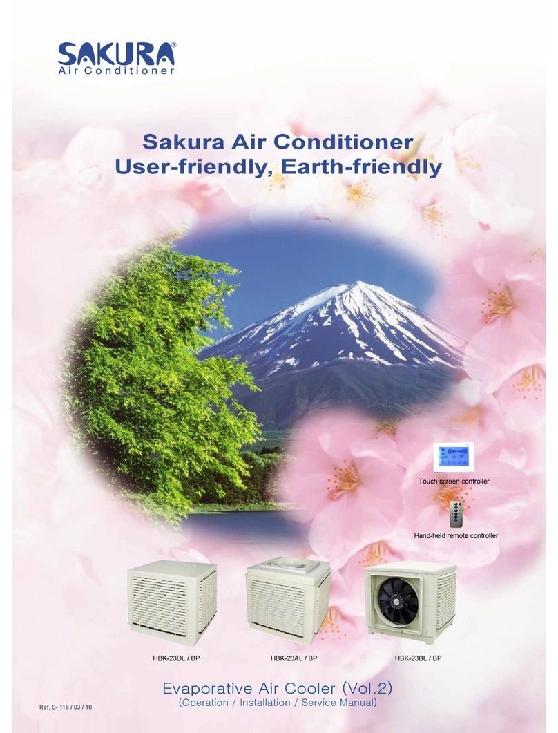
Fig.7 Fif.8
Fig.9

•The spaces between the unit and ceiling can now be adjusted. Use the drop rods to make the adjustment.
•Check to ensure the unit is level. The drain will then automatically be lower than the rest of the drip tray.
•Tighten the nuts on the suspended rods.
MODEL SFP-KM4
A (mm.) 3
15
SAKURA - Total Air Conditioning Solution

Fig.10
Fig.11
Fig.12

DRAIN PIPE WORK
Indoor Unit
•The unit is fitted with a condensate pump with a 500
mm. lift.
•The unit is provided with 22 mm. bore flexible hose
300 mm. long.
•The flexible hose should be fitted into a 22 mm O/S Φ.
polyvinyl tube and sealed. The drain must be
installed with a downward slope.
•On completion the drain line should be insulated.
WATER CONNECTIONS
•Water connections are fixed to the unit body to avoid breaks when pipes are connected to valve
assemblies; it is advisable to tighten the connection with a spanner.
•The upper coil connection is supplied with air purge screw, the lower connection with water purge screw,
suitable for 8mm. wrench or screw-driver.
•Coil is partially drainable; it is advisable to blow air into the coil for complete drainage.
EXTENDED DRAIN PAN ACCESSORY
INSTALLATION PROCEDURES
•Align the two (2) screw holes in the fixing plate to the two (2) holes in the external drain pan.
•Make sure the drain pan is horizontal.
•Tighten the two screws and making sure the external drain pan is installed flush with the fixing plate.
When the installation is completed, it is necessary to wrap connecting pipe with insulation to prevent leakage to
ceiling tile.
16
SAKURA - Total Air Conditioning Solution
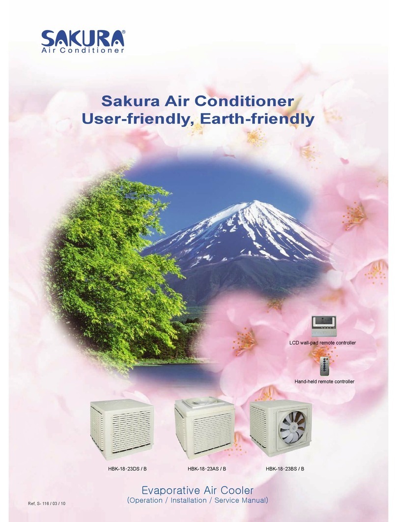
Fig.16

We recommend that screened cable be used in electrically noisy areas.
1. Always separate low voltage (5VDC) signal wires from power line (230 VAC) to avoid electro-magnetic
disturbance of control system.
2. Do not install the unit where electromagnetic waves are directly radiated at the infra red receiver on the unit.
3. Install the unit and components as far away as is practical (at least 5 meters) from the electromagnetic
wave source.
4. Where electromagnetic waves exist use shielded sensor cable.
5. Install a noise filter if any harmful noise exists in the power supply.
•Unlock the two fasteners on the front panel.
•Open the grille downward with care.
TERMINAL BLOCK
SFPKM4-34/51/68/80
MOUNTING FRONT PANEL ASSEMBLY
•Remove return grille from front panel.
•Move the front panel to casing.
•Tighten 4 screws as shown in Fig 17,18
TERMINAL BLOCK
SFPKM4-85-102/136/170/204/238
Fig 17 Fig 18
17
SAKURA - Total Air Conditioning Solution
INTER CONNECTING WIRING
FILTER REMOVAL

•Pull the filter out along the slot.
•Clean the filter and reassemble.
•The unit should not be started up until the system piping has been cleaned and all the air has been purged.
•Check condensate drain pipe slope.
•Make sure that air filter is clean and properly installed.
•Ensure that voltage and current values correspond with the unit nameplate values; check electrical connections.
•Verify that air outlets are not closed.
•Before performing any service or maintenance operations, turn off the main power switch.
•The air filter is made of acrylic fiber and is washable in water. To remove filter simply open the intake grille by
releasing the two catches. See Fig.19 and the section filter removal.
•Check the filter periodically and before the operating season; clean or replace as necessary.
PROLONGED UNIT SHUT-DOWN
•Prior to restarting the unit:
•Clean or replace the air filters.
•Check and remove any obstruction from the external drain pan and the internal drain pan.
EXTRA MAINTENANCE
•The electrical panel is easily accessible by removing the cover panel.
•The inspection or replacement of internal components such as; heat exchanger coil, condensate
Drain pump, float switch, involves the removal of the condensate drain pan.
See Fig.20-25.
•During the removal of the condensate drain pan protect the floor under the unit with a plastic sheet from
condensate water that could be spilled.
Fig.19
18
SAKURA - Total Air Conditioning Solution
PRELIMINARY CHECKS BEFORE START-UP
MAINTENANCE

•Remove fixing screws of the drain pan fixture and remove condensate drain pan with care.
The appliance are intended to be maintained by qualified service personnel
and located at a level not less than 2.5m.
Fan blower Removal
Fan
Fig.20 Fig.21
19
SAKURA - Total Air Conditioning Solution
Table of contents
Other Sakura Air Conditioner manuals
Popular Air Conditioner manuals by other brands

Technibel
Technibel CA92R5TA Series Technical data & service manual

Dowell
Dowell ARC-30 instruction manual

TemperZone
TemperZone OSA 83RKSH Installation & maintenance

Hitachi
Hitachi RAS-07BH2 Instruction and installation manual

Toshiba
Toshiba MMU-AP0072H2UL-1 Service manual

Qlima
Qlima Coolfair S1629 operating manual

Danby
Danby Silhouette DAC7024DE use and care manual

Mitsubishi Electric
Mitsubishi Electric Mr. SLIM PCA-A GA Series installation manual

Midea
Midea MFJ-24ARN1-QB8 Technical & service manual

INVENTOR
INVENTOR ARCMI-12 installation manual

Gree
Gree GWH07QB-K6DNB2E/O owner's manual

Mitsubishi Electric
Mitsubishi Electric MSZ-AY25VGKP operating instructions