Sakura FASN 080-600 User manual

Ref, S-(TC) 236-2 / 06 / 16
R-22
Installation, Operaton & Maintenance Manual
Sakura Air-cooled Split Ducted Air Conditioner
Models: FASN 080-600 / FASD 080-150

Safety Precautions ................................................................................................................... 2
Dimensions .............................................................................................................................. 3
Wiring Diagram ........................................................................................................................8
Installation ............................................................................................................................... 13
Indoor Unit Installation ................................................................................................. 13
Outdoor Unit Installation .............................................................................................. 14
Refrigerant Piping ......................................................................................................... 15
Servicing and Maintenance ...................................................................................................... 17
Troubleshooting ....................................................................................................................... 18
Contents
Page 1
Sakura Air-cooled Split Ducted Air Conditioner

Safety Precautions
Please read the following safety precautions carefully. Failure to follow safety precautions could result in death
or serious injury.
Important:
• Installation of equipment in corrosive, combustible or explosive environment is strictly prohibited.
• Do not use oxygen, acetylene, poisonous gas or any other gas that will cause an explosion during equipment
leak test.
Warning:
• Installation and maintenance should be performed by qualied personnel who are familiar with the product,
local codes and regulations.
• The equipment must be installed according to local rules and regulations.
• Field-installed wiring must comply with local codes and regulations, and must be carried out by qualied
personnel.
• Power supply must comply with unit’s name plate specications.
• The unit must be GROUNDED to prevent possible hazard due to insulation failure.
• Disconnect all electrical power before servicing in order to prevent electrical shock or injury caused
by direct contact with moving parts.
• When working with live electrical components, have a qualied electrician or other individual who has been
properly trained in handling live electrical components to perform these tasks.
• Electrical wiring must not be in contact with refrigerant piping, compressor or any moving parts of
the fan motors.
Caution:
• Avoid direct contact with sharp edges and coil surfaces, which are potential hazards for injuries.
• Ensure that the drainage piping is connected properly to prevent leakage of condensate water.
• Do not overcharge the equipment. Overcharging will cause over-current and damage the compressor.
Notice:
• This manual should be returned to unit’s designated place when installation is complete.
• This manual should be read carefully before installation. Unit installation and service should be performed
by experienced technicians in accordance with manual’s procedures to achieve normal and reliable unit
operation.
• This manual does not cover all unit differences and problems that may arise during installation.
Please contact our local sales ofce for further information and assistance.
• Warning and Caution will appear in appropriate sections throughout this manual, which should be rmly
followed to ensure safety and better operation performance. We claim no liability for unqualied
installation or service.
• The manufacturer reserves the right to revise any of the specications and designs contained herein at any
time without prior notication.
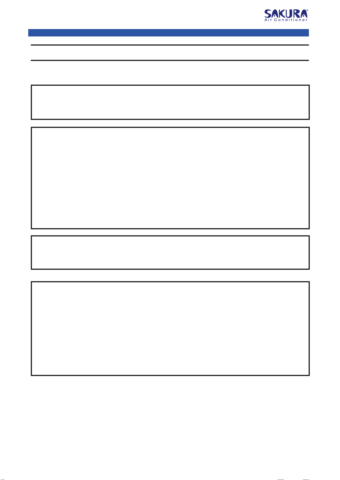
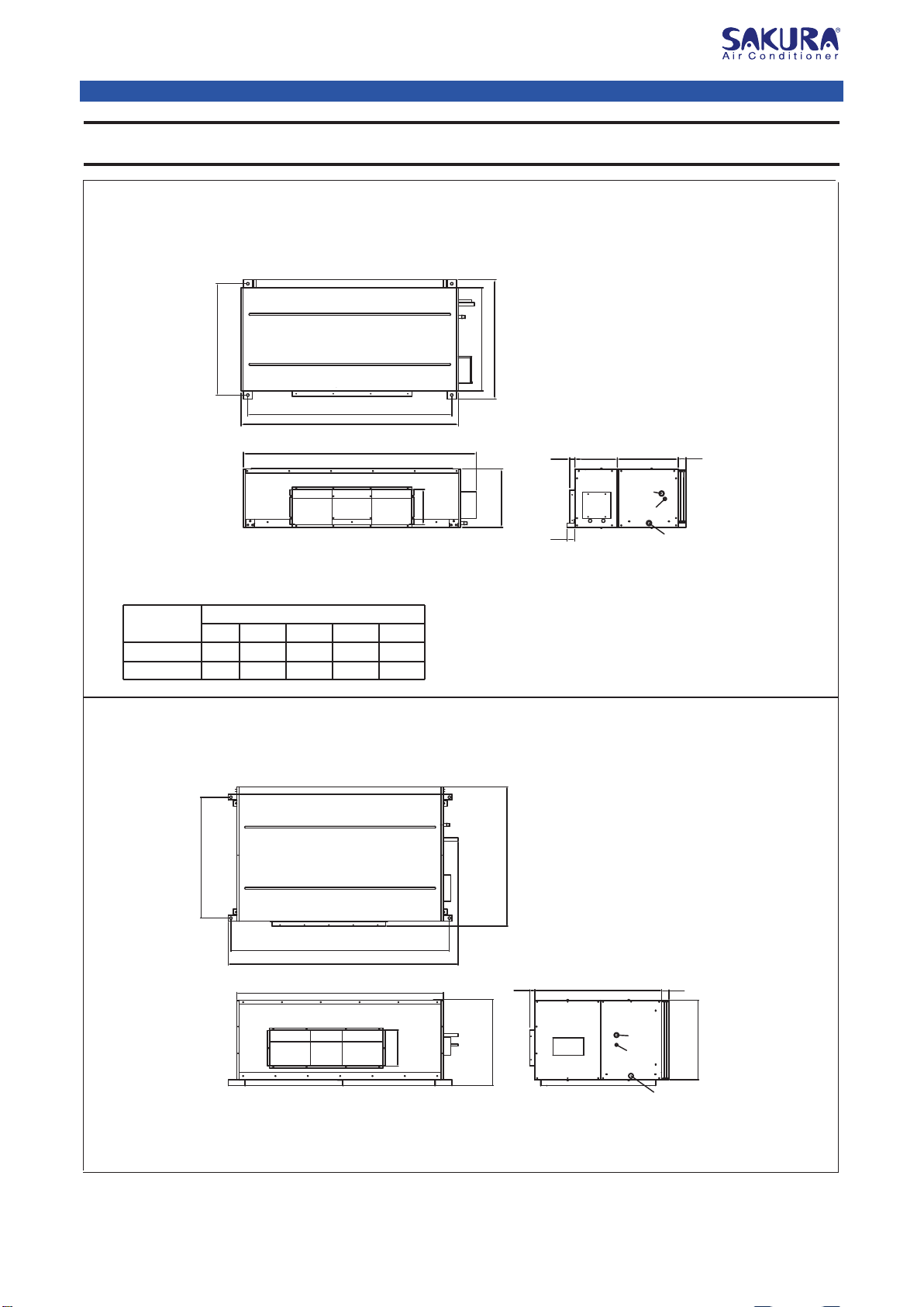
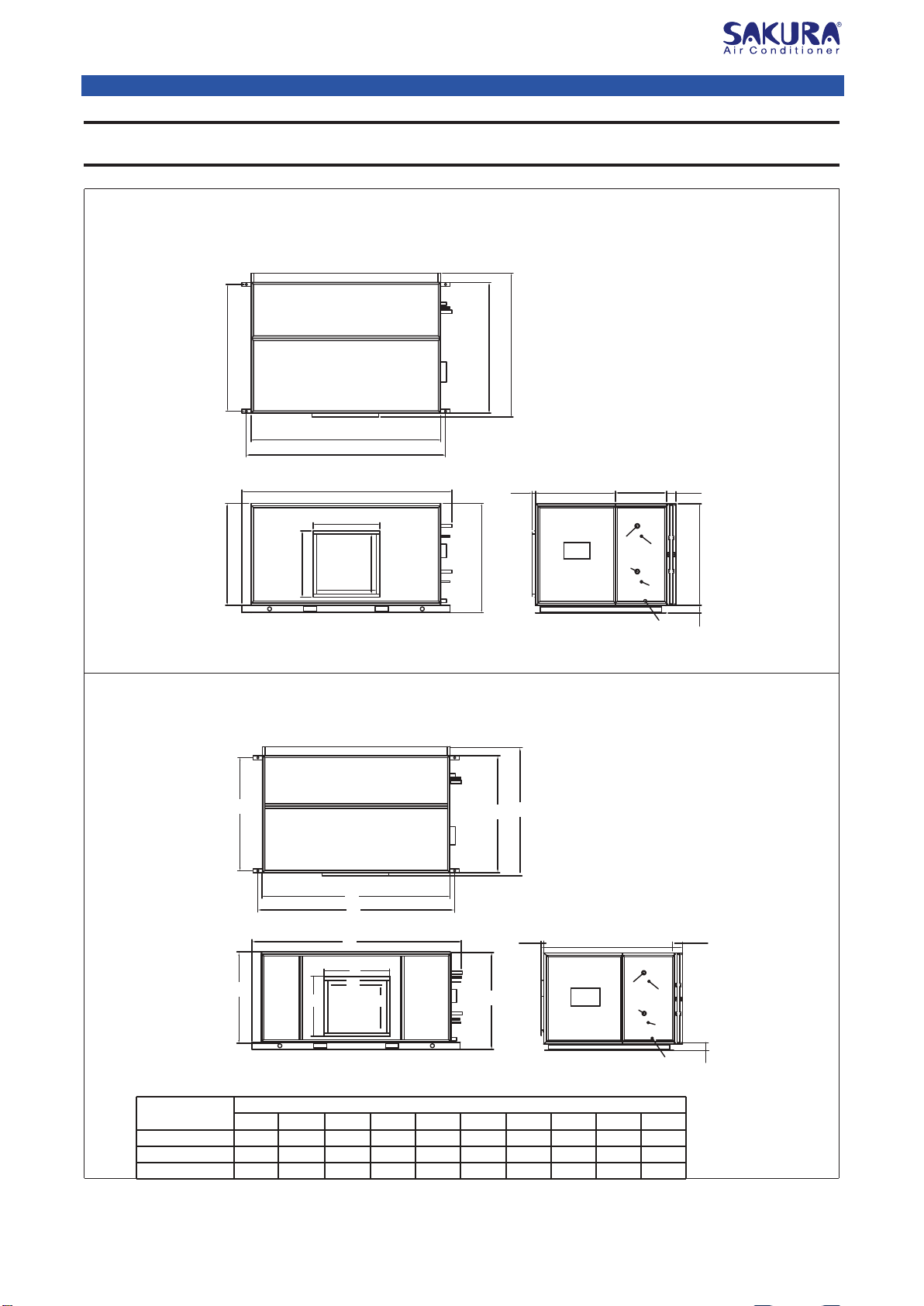
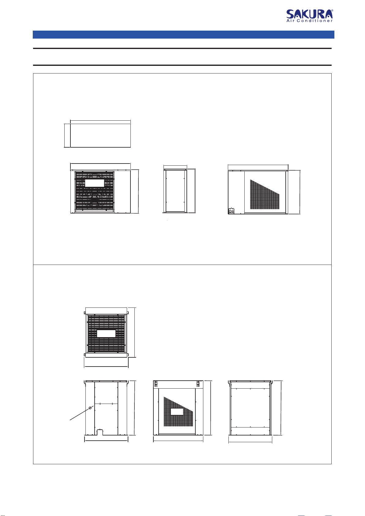
• Please refer to Technical manual for unit’s General Data and Controller Features.
Page 2
Sakura Air-cooled Split Ducted Air Conditioner

Dimensions
[unit:mm]
Model : FASN080 / 100
Model : FASN125 / 150
Model Dimension (mm)
A
783 261 1240 1340 1450
267 1540 1640 1750903
B C D E
FASN 080
FASN 100
Top View
Front View
Side View
Side View
32040
440
B
A
E
Top Panel
Air Discharge Flange
840
900
780
C
D
60
60
460
Condensate Water
Pipe
Filter
Side Panel
Suction
Pipe
Liquid Pipe
Service
Panel
Control
Panel
Blower
2
Blower
1
Front Panel
Control
Panel
Top View
Front View
707
60
650
1040
990
1140
Condensate Water
Pipe
Filter
Side Panel
Suction
Pipe
Liquid
Pipe
Service Panel
Control
Panel
Control
Panel
Front Panel
Unit Base
293
930
1693 40
1882
1790
Top Panel
Blower
2
Blower
1
Air Discharge Flange
[unit:mm]
Page 3
Sakura Air-cooled Split Ducted Air Conditioner

Dimensions
Control
Panel
Model : FASN200
Model : FASN250
Top View
Top View
Front View Side View
530
2286
2208
2084
40
1100
1157
1297
100
780
730
393
864
343
914
627
730
50
Top Panel
Condensate Water
Pipe
Filter
Side Panel
Suction
Pipe
Liquid
Pipe
Suction Pipe
Liquid
Pipe
Service
Panel
Front Panel
Control
Panel Control
Panel
657
1155
406
1094
2261
2141
2041
1164
1207
1347
Top Panel
1044
456
550 100
107580
Condensate Water
Pipe
Filter
Suction
Pipe
Liquid
Pipe
Suction
Pipe
Liquid
Pipe
Service Panel Side Panel
Blower
2
Blower
1
Control
Panel
Air Discharge Flange
[unit:mm]
[unit:mm]
Blower
1
Blower
2
Page 4
Sakura Air-cooled Split Ducted Air Conditioner

Dimensions
Model : FASN300
Model : FASN400 / 500 / 600
Top View
Front View Side View
Front View
Top View
Side View
100
80 1095
55085740
1175 1407
1364
1547
645
645
715
2261
2141
2041
715
1095
Side Panel
Filter
Suction
Pipe
Suction
Pipe
Liquid
Pipe
Liquid
Pipe
Condensate Water
Pipe
Service Panel
Control
Panel
Control
Panel
Blower
Top Panel
Top Panel
Air Discharge Flange
[unit:mm]
[unit:mm]
Model Dimension (mm)
A
2568 1450 1370 1407 1547
1450 1370 1497 1637
2348
26982918
1650 1570 1597 1737 26982918
B C D E F
2448
2798
2798
G
1364
1454
1554
H
715
790
880
I
645
720
810
J
FASN 400
FASN 500
FASN 600
E
Air Discharge Flange
Top Panel
Top Panel
Service Panel Side Panel
Filter
Suction
Pipe Liquid
Pipe
Suction
Pipe
Liquid
Pipe
80
100
Condensate Water
Pipe
40
Control
Panel
D
B
A
F
G
H
J
J
I
IBlower
Control
Panel
C
Page 5
Sakura Air-cooled Split Ducted Air Conditioner

Dimensions
Model : FASD080
Model : FASD100 / 125
Side View
Top View
Back ViewFront View
1308
508
1308
508
1308
Coil
Blower
951
Back ViewSide ViewFront View
Top View
1215
1213
967
1113
951
951
Coil
Blower
1215
967
986
1113
Ø50
[unit:mm]
[unit:mm]
Page 6
Sakura Air-cooled Split Ducted Air Conditioner

Dimensions
Back ViewSide View
Coil
Blower
Front View
1175
1110
967
1110
967
1225
[unit:mm]
Model : FASD150
Top View
Page 7
Sakura Air-cooled Split Ducted Air Conditioner

Wiring Diagram
Model : FASN 080 / 100 (With Control PCB)
Model : FASN125 / 150 (With Control PCB)
Connect To
Wallpad
(4 Cores Wires)
Indoor
Temperature
Sensor
Inner Coil
Temperature
Sensor (Copper)
Transformer
FM
T
RS
KM
FR
NPE
Connect To Outdoor
YLW/GRN
BLUE
YELLOW
RED
KM - AC Contactor FR - Thermal Relay
Note: Installation Connection
To Power Supply 380-415V/3Ph/50Hz
PE
L
comp
YLW/GRN
N
RED
YLW
HP
LP
FR
KM
WHT
BLK
BLUE
BLUE
PCB N1
N2
Live
Comp
X
1
SEC
2
PRI
1 3
N4 RM IDCON
N3
LP
HP
MED
LOW
HI
Live
Comp
X
1
SEC
2
PRI
1 3
Connect To Outdoor
KM - AC Contactor FR - Thermal Relay
Note: Installation Connection
HI
MED
LOW
PE
L
comp
YLW/GRN
N
RED
YLW
HP
LP
WHT
BLK
BLUE
RED
BLUE
FM2 FM1 C
C
YLW/
GRN
YLW/GRN
WHT
BLK
BLK
H[22]
H
M
L
Live
Live
Live
L1 [1]
M[21]
L[20]
N
BLUE
RED
BLUE
RED
BLUE
Relay Board
PCB
Connect To
Wallpad
(4 Cores Wires)
Indoor
Temperature
Sensor
Inner Coil
Temperature
Sensor (Copper)
Transformer
N4
RM IDCON
N3
LP
HP
Page 8
Sakura Air-cooled Split Ducted Air Conditioner

Wiring Diagram
PE
YLW/GRN
N
comp1 L
comp2
LP1/HP1
Dip Switch
FM
T
RS
KM
FR
NPE
Connect To Outdoor
KM
YLW/GRN
LP2/HP2
RED
BLUE
BLUE
YELLOW
RED
YLW
WHT
WHT YLW
Note: KM - AC Contactor FR - Thermal Relay-------------- Installation Connection
To Power Supply 380-415V/3Ph/50Hz
COM
Dip Switch Setting
12345 6 7 8
000000 0 0
Note: 0 - OFF, 1 - ON
RED
FR
Switching
Power Supply
Board (SMPS)
Inner Coil
Temperature
Sensor (Copper)
Indoor Temperature
Sensor
Connect To Wallpad
(4 Core Wires)
BMS Connection
On Port
A12
A11
Indoor Blower
Compressor 1
Compressor 2
Relays
I.C
Live1
Live2
D01
D02
D03
D04
D05
N
COMP 2
D11
D12
D13
D14
D15
D16
D17
D18
PE
YLW/GRN
N
comp1 L
comp2
LP3/HP3
FM
T
RS
KM
FR
NPE
Connect To Outdoor
To Power Supply 380-415V/3Ph/50Hz
KM
YLW/GRN
LP4/HP4LP2/HP2LP1/HP1 comp3 comp4
RED BLUE
BLUE
YELLOW
RED
YLW YLW YLW YLW
WHT
WHT
WHT
WHT
Note:KM - AC Contactor FR - Thermal Relay --------------- Installation Connection
COM
Dip Switch Setting
1 2 3456 7 8
110000 0 0
Note: 0 - OFF, 1 - ON
RED
FR
Switching
Power Supply
Board (SMPS)
Indoor Blower
Compressor 1
Compressor 2
Compressor 3
Compressor 4
Relays
I.C
Live1
Live2
D01
D02
D03
D04
D05
N
COMP 2
D11
D12
D13
D14
D15
D16
D17
D18
Inner Coil
Temperature
Sensor (Copper)
Indoor Temperature
Sensor
Connect To Wallpad
(4 Core Wires)
BMS Connection
On Port
A12
A11
Dip Switch
PCB
PCB
Model : FASN400 / 500 / 600 (With Control PCB)
Model : FASN200 / 250 / 300 (With Control PCB)
Page 9
Sakura Air-cooled Split Ducted Air Conditioner

Wiring Diagram
Model : FASD080 / 100 / 125 / 150
(With Control PCB - Single Stage)
Model : FASD100 / 125 / 150 (With Control PCB - Multi Stage)
YLW/GRN
RED
WHT
BLK
YLW/GRN
RED
BLK
WHT
R
S
T
N
R/A S/B T/C
95/11 96/12 98/14
RVR
COMP
RED
YLW
L N
PE
BLU
YLW/GRN
LP/HP
COM
Note: Installation Connection
KM - AC Contactor HP - High-Pressure Switch LP - Low-Pressure Switch
RVR - Ele Protector DT - Discharge Temperature Protector FR - Thermal Relay
To Power Supply 380-415V/3Ph/50Hz
(To Indoor Unit)
RED WHT
θ
FR2FR1
KM1
KM2
LPDTHP
P
CM FM
YLW/GRN
RED
WHT
BLK
YLW/GRN
RED
BLK
WHT
R
S
T
N
R/A S/B T/C
95/11 96/12 98/14
RVR
COMP
WHT REDYLW
L N
PE
HP
BLU
YLW/GRN
θ
LP
BLK
Note: Installation Connection
KM - AC Contactor HP - High-Pressure Switch LP - Low-Pressure Switch
RVR - Ele Protector DT - Discharge Temperature Protector FR - Thermal Relay
To Power Supply 380-415V/3Ph/50Hz
(To Indoor Unit)
KM2
FR2
KM1
CM FM
FR1
FR2FR1
KM1
KM2
LP
DTHP P
P
Page 10
Sakura Air-cooled Split Ducted Air Conditioner

Wiring Diagram
Model : FASN080 / 100 (Without Control PCB)
FM1FM2
FM
3 Speeds ON/OFF
Switch
To Power Supply 220-240V/1Ph/50Hz
FL NFH
CC
Note: ---------Installation Connection
RED WHITE
BLUE
BLACK
YLW/GRNYLW/GRN
Model : FASN 125 / 150 & FASN200 / 250 / 300 / 400 /
500 / 600 (Without Control PCB)
R S T N
FM
YELLOW
PE
YELLOW / GREEN
Note: -------- Installation Connection
BLUERED
To Power Supply 380-415V/3Ph/50Hz
Page 11
Sakura Air-cooled Split Ducted Air Conditioner

Wiring Diagram
R S T
RED
WHITE
BLK
NPE
YELLOW/GREEN YELLOW/GREEN
LP2
LP1 HP2
HP1
Note: ---------- Installation Connection
RED
WHITE
BLK
To Power Supply 380-415V/3Ph/50Hz
CM FM
Model : FASD080 / 100 / 125 / 150 (Without Control PCB)
Page 12
Sakura Air-cooled Split Ducted Air Conditioner

Warning:
Installation
Please pay attention to the following:
• Please check the equipment with your check list after receiving the unit.
• Please keep the unit horizontal and balanced before hanging up the unit.
• Please ensure proper equipment (e.g., fork lift, hoist, sling, etc.) is used when handling the unit.
• Please remove all packaging material after installation.
If there are any problems or the unit is damaged, please contact authorized dealer.
1. Indoor Unit Installation
Carefully plan the installation location with the following considerations:
• Easy distribution of air ducts.
• Space for connection of refrigerant pipes, wirings and water pipes.
• Ceiling/structure is strong enough to support the unit.
• For noise consideration, always install unit away from air conditioned area.
• Always allow sufcient space for servicing and maintenance as shown in the following diagram:
• Use the hanging rods to hang the unit through the holes provided. Strength of hanging rods must be
able to support the total weight of the unit.
• During operation of the unit, there will be plenty of condensate water that needs to be discharged. In order to
prevent overow of condensate water, the water must be drained through condensate water pipe.
Please ensure a gradient is maintained as shown in the following diagram.
Unit should be installed by qualied technicians. Installation should adhere to local code and regulations.
• To reduce noise transmission through hanging rod, it is recommended to install rubber dampers or isolators.
• Mufer can be used to reduce noise transmission through air duct if the unit needs to be installed near
air conditioned area.
Minimum 800mm
Condensate
0-10mm
water pipe
Page 13
Sakura Air-cooled Split Ducted Air Conditioner

Condensate drain pipe installation:
• For easy drainage of condensate water, drain pipe must be sloped
downward at least at a gradient of 1:100.
• The drain pipe must have a U-bend.
• Drain pipe that runs under the ceiling or within the air conditioned
space should be insulated to prevent condensation of water.
Choice of insulation material can be PE, PU or other appropriate
insulation material.
Air Ducting Installation
• There are two types of discharge air-duct, namely rectangular and round ducts.
• Rectangular ducts can be connected to the discharge of the indoor unit directly. Refer to the dimension
drawing of the unit to see the dimensions of the discharge.
• Flexible connection must be installed between air ducts and indoor unit to ensure quiet operation.
• A reducer is necessary to connect the round duct to the discharge of the unit.
• Design of supply and return air duct should strictly adhere to the maximum static pressure that can be
delivered by the unit to avoid unsatisfactory unit performance and overload of fan motors.
2. Outdoor Unit Installation
To ensure the unit operates at optimum performance level and to maintain long life-span of components, the
choice of location of unit and installation recommendations as listed below should be followed:
• The discharge air and intake air direction of outdoor unit should not be blocked to ensure there is no
short circuiting of hot air.
• If there is more than 1 unit being installed at the same location, make sure that the discharge of one unit
does not face the air intake of another.
• The location of installation should be well ventilated and avoid direct sunlight.
• Location of installation should be able to drain rain water or condensation water.
• Ensure the location of installation does not face strong wind and is free from dust.
• Do not connect duct to the outdoor fan discharge.
• Do not install the unit at location that is near corrosive materials or chemicals.
• Avoid installing the outdoor unit under the window.
• Ensure the discharge of air and noise generated during operation do not affect the surrounding neighbors.
Note:
A U-bend must be installed along the
drain pipe. The recommendation is as
following:
100mm<h<150mm and x>h/2
h
x
Page 14
Sakura Air-cooled Split Ducted Air Conditioner

Installation Clearance
To provide sufcient service clearance and to ensure good air intake and discharge, please refer to the
recommendation as follows:
Refrigerant Piping
Long refrigerant piping will affect the performance of the unit and shorten the lifespan of compressor. In the
worst-case scenario, it will cause the compressor to break down. Special precaution needs to be taken to
make sure that the maximum length of the piping strictly adheres to the recommended maximum pipe
length and elevation in the following tables:
35 20 8
8
8
8
8
8
8
8
8
8
20
20
20
20
20
20
20
20
20
35
35
35
35
35
35
35
35
35
FASN080
FASN100
FASN125
FASN150
FASN200
FASD080
FASD100
FASD100 X 4
FASD100 X 2
FASD125
FASD125 X 2
FASD125 X 4
FASD150
FASD150 X 2
FASD150 X 4
FASN250
FASN300
FASN400
FASN500
FASN600
Model Maximum
Length (m)
Maximum
Elevation (m)
Maximum
Bends
Min 1500mm
Min 1200mm
Min 500mm
Min 500mm
Min 700mm
Min 700mm
Page 15
Sakura Air-cooled Split Ducted Air Conditioner

Vacuuming and Refrigerant Charging
Vacuuming is necessary to eliminate all moisture and air from the system.
Vacuuming
After the system piping is properly connected, vacuum the air conditioner system to at least 500 microns Hg.
Charging
Before charging, the vacuum must be held at 500 microns Hg for at least 15 minutes. After charging, operate
the unit for 15 minutes, ensuring that refrigerant charges is of correct quantity by monitoring running
current and suction and liquid line pressures. Suction and discharge pipe pressures should be in the region
of 75 psig and 275 psig. After ensuring the system is correctly charged, remove exible hose from charging
nipples and replace with caps.
Attention:
Outdoor unit is not factory pre-charged with refrigerant.
Page 16
Sakura Air-cooled Split Ducted Air Conditioner

Servicing and Maintenance
Indoor Unit
• Air Filter
The lter must be cleaned regularly and the frequency of cleaning is to be determined by the degree of
pollution of the environment of application. When washing the lter, rst tap it gently to remove larger particle,
and then rinse the lter in detergent and warm water. The lter must be dried before it is used. The lter is
recommended to be installed before the air grille or the indoor coil.
• Motor
It is not necessary to lubricate the motor for servicing and maintenance.
• Heat Exchanger
After in use for a while, the surface of the coil may collect dust, dirt or other undesirable substances. It is
recommended to clean the aluminum ns of the coil using a nylon brush or vacuum cleaner. If compressed
air is available, it can be used to clean the coil by direct blowing.
However, care must be taken not to damage the ns.
• Drain Pipe
Check the drain pipe regularly to prevent blockages by alien substances.
Outdoor Unit
Under normal operating conditions, outdoor unit should be checked quarterly and the coil surface should
be washed. If the outdoor unit is installed at location which is oily, smoky and dusty, regular service should be
done by a technician to make sure that the heat exchanger is always in optimum condition.
Warning
Do not use oxygen, acetylene, poisonous gas or any other gas that will cause explosion under high
temperatures and pressure for leak checking. Instead, use nitrogen or R22 for air leakage test.
Page 17
Sakura Air-cooled Split Ducted Air Conditioner

Troubleshooting
Fault Possible Cause Solution
Abnormal Noise
Supply Air Too
Low
Supply Air Too
High
Air Velocity Too
High
Insufficient
Fresh Air
10. Fan too small.
1. Clean or change lter.
10. Reselect fan.
9. Change deector.
1. Dirty lter.
2. Check and seal the leakage.2. Leakage in duct.
3. Clear the air duct or open the air vent.
4. Fan rotates in wrong direction.
5. RPM too low. 5. Change fan motor or pulley.
6. Fan or fan motor undersized. 6. Change fan motor or pulleys.
1. Oversized fan or and motor. 1. Reselect fan or fan motor.
1. Air velocity too high at vent. 1. Extend vent area.
2. Airow unstable.
Not enough fresh air supply.
1.Fully open fresh air vent.
2. Clean fresh air lter.
2. RPM too high. 2. Change fan motor or pulley.
1. Blower blade or blower shaft loose. 1. Tighten the shaft.
2. Blower or blower housing dirty. 2. Clean blower.
3. Duct or modulating valve loose. 3. Repair duct and modulating valve.
4. Fan belts not align or loose. 4. Align or tighten fan belt.
5. Nuts and bolts for motor, fan or motor
base loose. 5. Tighten the nuts and bolts.
6. Flexible duct at intake / discharge too
tight.
6. Re-adjust the exible duct. Change if
necessary.
2. Change vent size or add extra
deflector to rectify airflow.
3. Increase cross-sectional area of fresh air duct.
3. Air duct is blocked or air vent is not
open.
4. Reverse the phase of power supply.
9. Deflector too small or duct elbow
over turn to produce noise.
8. Clean the bearing and re-apply lubrication oil.
8. Lubrication is bad or no lubrication.
7. Fan operating point is not optimum. 7. Re-select fan motor or pulley.
Page 18
Sakura Air-cooled Split Ducted Air Conditioner

SAKURA CORPORATION
Tel: (81)45-949-8550 Fax: (81)45-949-8551
2-17-1. Eda-minami, Tsuzuki-ku, Yokohama, Kanagawa, 224-0007, Japan
This manual suits for next models
13
Table of contents
Other Sakura Air Conditioner manuals