Sakura SFP-KM-DLY Series User manual

Sakura Air Conditioner
User-friendly, Earth-friendly
Sakura Air Conditioner
User-friendly, Earth-friendly
Ref, S- 091 / 03 / 10 (A)
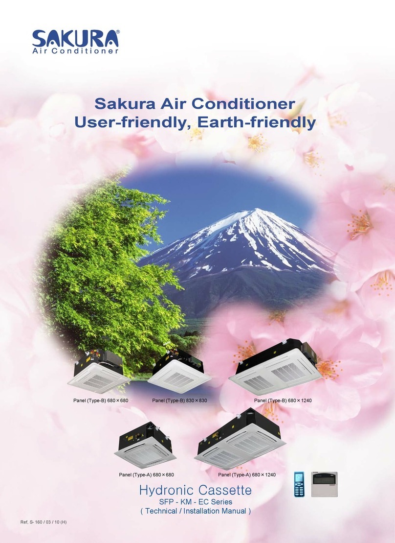
Hydronic Cassette
SFP - KM - DLY Series
( Technical / Installation Manual )
SINGLE FAN (4-way discharge)
TWIN FAN (6-way discharge)

DLY (DELUXE) SERIES HYDRONIC CASSETTE
2
INDEX OF THE MANUAL
1. CASSETTE MODEL ASSIGNMENTS 3
2. BRIEF INTRODUCTION OF THE UNIT
RANGE 4
AVAILABLE SIZES & MOELS 4
MAIN COMPONENTS OF THE UNIT 4
UNIT DESCRIPTION 5
3. SPECIFICATIONS
SPECIFICATIONS – 2 PIPE SYSTEM 7
SPECIFICATIONS – 4 PIPE SYSTEM 11
4. INSTALLATION
1) PACKAGE CHECKING 14
2) SAFETY CAUTIONS 14
3) OPERATING LIMITS 14
4) INSTALLATION LOCATION 14
5) INSTALLATION OF THE UNIT 14
6) CONDENSATE DRAINAGE CONNECTION 17
7) WATER CONNECTIONS 17
8) EXTERNAL AUXILIARY DRAIN PAN INSTALLATION 17
9) MOUNTING UNIT PANEL 18
10) ELECTRICAL CONNECTION 18
11) EXTERNAL FRESH AIR,
DELIVERY OF TREATED AIR TO ADJACENT ROOM 19
12) MAINTENANCE AND SERVICE 20
5. DIMENSIONAL DRAWINGS 22
6. REMOTE CONTROL HANDSET
OPERATION OF REMOTE HANDSET 27
INSTALLATION OF REMOTE HANDSET 28
7. WIRED WALL PAD (OPTIONAL)
WALL PAD BUTTONS 29
WALL PAD OPERATION 30
WALL PAD INSTALLATIONS 33
8. CONTROL SPECIFICATIONS 34
SENSOR RESISTANCE R-T CONVERSION TABLE 44
9. CONTROL AND POWER SUPPLY WIRING DIAGRAMS 46
10. VALVE & VALVE CONNECTIONS (OPTIONAL) 50
11. MASTER – SLAVE NET WORK 56
BMS – HOST COMPUTER NET WORK (OPTIONAL) 59
12. TROUBLE SHOOTING 73
SAKURA - Total Air Conditioning Solution

DLY (DELUXE) SERIES HYDRONIC CASSETTE
.
3
CASSETTE TYPE FAN COIL UNITS
MODEL ASSIGNMENTS
Model Name / Commercial Code
SFP - 68 KM 4 - V / DL Y
Y PANEL Y (for KM4,KM6)
E PANEL E-II (for KM4,KM6)
DL DELUXE SERIES (for KM4,KM6)
CF COMFORT SERIES (for KM4)
PF PUMP FREE SERIES (for KM4)
-- (for KM1,KM2)
V 2 PIPE SYSTEM
P 4 PIPE SYSTEM
6 6 WAY DISCHARGE (twin fan)
4 4 WAY DISCHARGE (single fan)
2 2 WAY DISCHARGE
1 1 WAY DISCHARGE
KM CASSETTE TYPE
68 NOMINAL AIR FLOW *10M3/H
SFP FAN COIL UNIT
SAKURA - Total Air Conditioning Solution

DLY (DELUXE) SERIES HYDRONIC CASSETTE
.
4
BRIEF INTRODUCTION OF THE UNIT
RANGE
The cassette type fan coil unit is a terminal for the treatment of air in a room by chilled and/or hot water. The unit is
ceiling-mounted with the possibility of treating fresh air outside air and sending treated air to the adjacent room(s).
z2 pipe system by chilled or hot water.
z2 pipe system with electric heater as booster or primary heater.
z4 pipe system by chilled and hot water.
AVAILABLE SIZES & MODELS
AIR FLOW
SIZE
CODE M3/H CFM
2 PIPE 2 PIPE
With E. Heater 4 PIPE UNIT
PANEL
34 450 260 ¥¥ --
51 510 300 ¥¥ --
68 680 400 ¥¥ ¥
80 800 450 ¥¥ ¥
680x680
85 850 500 ¥¥ ¥
102 1,020 600 ¥¥ ¥
136 1,360 800 ¥¥ ¥
830x830
170 1,700 1,000 ¥¥ ¥
204 2,040 1,200 ¥¥ ¥
238 2,380 1,400 ¥¥ ¥
980x980
289 2,890 1,700 ¥¥ ¥1140x1140
85 850 500 ¥¥ ¥
102 1,020 600 ¥¥ ¥
136 1,360 800 ¥¥ ¥
170 1,700 1,000 ¥¥ ¥
680x1240
Table 1
MAIN COMPONENTS OF THE UNIT
LAMP BOARD
1. Under heating operation, the red color LED
lamp on.
2. When timer function active, the yellow color
LED lamp on.
3. Under cooling operation, the green color
LED lamp on.
4. RESET: press to turn on/off the unit
manually.
1ˊRemote handset & handset wall holder
2ˊUnit panel
3ˊLouver
4ˊPre-stamped hole(s) for external fresh air and
delivery of treated air to adjacent room
5ˊUnit body
6ˊMounting brackets
7ˊCoil connection supporter
8ˊCoil connection with air vent and partial
drainage vent
9ˊExternal auxiliary drain pan
10ˊControl box
11ˊDrainage pump maintenance board
12ˊCondensate drainage pipe
13ˊLamp board (Receiver)
14ˊAir return grille
15ˊDrainage hose
SAKURA - Total Air Conditioning Solution

DLY (DELUXE) SERIES HYDRONIC CASSETTE
.
5
UNIT DESCRIPTION
PANEL ASSEMBLY with attractive and elegant design.
Panel style –Y with available 5 sizes (Table 1).
Single Fan Cassettes with the smallest panel are
applicable for one unit of European standard false
ceiling (600x600mm).
Twin Fan Cassettes are applicable for two units of
European standard ceiling (600x1200mm).
AIR DELIVERY LOUVER
The internal surface is treated by fiber plating
technology and with wave shape, efficiently preventing
the condensate water blowing into the room. (Fig.1)
AIR FILTER installed with the air inlet grille is
moveable and washable.
AIR VENTURI is equipped with a protective grille that
impedes access to the moving fan. (Fig.2)
UNIT BODY CASING is made of galvanized steel and
both internal and external surface are thermal acoustic
insulated preventing the condensate water and
ensuring the silent operation.
EXTERNAL FRESH AIR
There is one pre-stamped hole on unit body for
introducing outside fresh air. (Fig.3)
DELIVERY TREATED AIR TO ADJACENT ROOM:
There are pre-stamped holes on unit body for delivery
of treated air to the adjacent room.(Fig.3)
HEAT EXCHANGER is composed of copper pipes
with attached corrugated aluminium blue fins. Coil data
see table 2.
The coil connections are provided with air vent and
partial water drainage vent. (Fig.4)
The coil connections are attached with connection
supporter. (Fig.4)
CONDENSATE DRAIN DEVICE
The unit is equipped with a high density polystyrene
foam main condensate drain pan, a three level float
switch, a no return valve and a pump with 70cm max.
head.
EXTERNAL AUXILIARY DRAINE PAN
For collecting condensate from the valve piping and
transporting it to the main condensate drain pan.(Fig.5)
PUMP MAINTENANCE BOARD is opened at the side
of unit body for easily service of the drainage pump in
the case of necessary.(Fig.6)
FAN BLOWER & FAN MOTOR
The balanced centrifugal fan blower and fan motor can
be accessed through the window of air return grille,
easily for service.
THE 3-SPEED MOTOR (STANDARD)
The unit is standard equipped with 3 speeds motor.
THE 5-SPEED MOTOR (OPTIONAL)
The 5 speeds electric motor with 3 speeds connected
and it is possible to change them on site if necessary.
CONTROL BOX
The PCB, capacitor, transformer, power terminal are
installed in the control box attached external of the unit
body.
Full series units are using the same one PCB.
Configuration of the 2/4 pipe system, electric heater,
master-slave address are through the DIP switches
and jumpers on PCB.
ADVANCED CONTROL SYSTEM
- LCD Remote handset with wall holder
- LCD Wired wall pad (optional)
- Operation Modes: Cool, Fan, Dry, Heat, Auto.
[Auto cool/heat is for 4 pipe system]
- Weekly Timer
- Auto-restart
- Motorized valve control
- Electric heater control as booster or primary.
[For 2 pipe system]
- Master/Slave working control [Max.32 units]
- Host computer control [Max.2048 units]
ELECTRIC HEATER (OPTIONAL)
Electric heater is optional components for 2 pipe
system. It can be set as booster heater or as primary
heater.
The electric heater is equipped with manual and auto
protection switches.
ON/OFF 3-WAY 4 OUTLET VALVE (OPTIONAL)
[External installation]: The 3 way 4 outlet on/off valve
and valve connecting kits are available as optional
parts.
[Internal installation]: The 3 way 4 outlet on/off valve
pre-installed at factory is available as optional.
ON/OFF 2-WAY VALVE (OPTIONAL)
[External installation]: The 2 way on/off valve and valve
connecting kits are available as optional parts.
[Internal installation]: The 2 way on/off valve pre-
installed at factory is available as optional.
SAKURA - Total Air Conditioning Solution

DLY (DELUXE) SERIES HYDRONIC CASSETTE
.
6
Fin Length (mm.)
COIL DATA
2 PIPE MODEL
Fin Height
(mm) Inner Outer
Fins per
Inch
No. of
rows
No. of
circuits
Tube
Diameter
FP-34/51/68/80KM4-V 225 1145 1349 14.1 2 8 3/8’’
FP-85/102/136KM4-V 225 1535 1739 14.1 2 8 3/8”
FP-170/204/238KM4-V 250 1922 2126 14.1 2 9 3/8”
FP-289KM4-V 250 2348 2552 14.1 2 9 3/8”
FP-85/102/136/170KM6-V 225 2243 2447 14.1 2 8 3/8”
Fin Length (mm.)
COIL DATA
4 PIPE MODEL
Fin Height
(mm) Inner Outer
Fins per
Inch
No. of
rows
No. of
circuits
Tube
Diameter
FP-68/80KM4-P 225 1145 1349 14.1 2 5/3 3/8’’
FP-85/102/136KM4-P 225 1535 1739 14.1 2 5/3 3/8”
FP-170/204/238KM4-P 250 1922 2126 14.1 2 6/3 3/8”
FP-289KM4-P 250 2348 2552 14.1 2 6/3 3/8”
FP-85/102/136/170KM6-P 225 2243 2447 14.1 2 5/3 3/8”
Table 2
SAKURA - Total Air Conditioning Solution
S
S
S
S
S
S
S
S
S
S

DLY (DELUXE) SERIES HYDRONIC CASSETTE
.
7
SPECIFICATIONS – 2 PIPE SYSTEM
(4-WAY DISCHARGE SINGLE FAN CASSETTE)
Cooling: Entering air temperature: Dry bulb 27ºC, Wet bulb 19ºC;
Inlet water temp. 7ºC; Outlet water temp. 12ºC;
Heating: Entering air temperature: 20ºC;
Inlet water temp. 50ºC; Same water flow rate as for the cooling;
The customized power of electric heater is available.
The electric heater can be set as auxiliary heater booster or as primary heater, see control specifications.
SFP-34KM4-V/DLY SFP-51KM4-V/DLY SFP-68KM4-V/DLY SFP-80KM4-V/DLY
Total capacity
(H/M/L) kW 2.3/1.9/1.6 3.0/2.2/1.85 3.8/3.2/2.75 4.1/3.4/2.85
Sensible capacity
(H/M/L) kW 1.75/1.45/1.2 2.4/1.65/1.4 2.7/2.2/1.85 3.0/2.6/1.95
Water flow rate L/h 370 480 620 680
Pressure drop kPa 1 2 2.5 4.5
Hot Water Heating Capacity
(H/M/L) kW 3.4/2.75/2.3 4.0/3.2/2.7 5.4/4.1/3.2 5.5/4.3/3.3
Evaparator Coil Water content L 1.4 1.4 1.4 1.4
Type
Size (Dia.) mm 315 315 315 315
No.offan 1111
Power supply V/Ph/Hz
Power input W 39 54 58 64
Running current A 0.18 0.24 0.27 0.29
m3/h 450/360/300 510/410/350 680/520/400 800/630/470
dB(A) 31/30/29 34/30/29 39/33/29 43/37/31
kW 2.0 2.0 2.0 2.0
A 9.0 9.0 9.0 9.0
mm
mm
kg
Method
In mm(in)
Out mm(in)
Water Connection
220~240/1/50(60)
Chilled Water Cooling
Air Flow (H/M/L)
Electric Power
Panel Dimensions
Operation Control
19.05(3/4")
Socket (Threaded Female)
19.05(3/4")
Fan Blower
Model
Centrifugal type fan blower
25
680x680x30
581x581x290
Wireless remote controller and/or Wired wall pad
Electric Heater (optional)
Sound Pressure (1m,H/M/L)
Net Weight
Unit Dimensions (LxWxH)
SAKURA - Total Air Conditioning Solution

DLY (DELUXE) SERIES HYDRONIC CASSETTE
.
8
SPECIFICATIONS – 2 PIPE SYSTEM
(4-WAY DISCHARGE SINGLE FAN CASSETTE)
Cooling: Entering air temperature: Dry bulb 27ºC, Wet bulb 19ºC;
Inlet water temp. 7ºC; Outlet water temp. 12ºC;
Heating: Entering air temperature: 20ºC;
Inlet water temp. 50ºC; Same water flow rate as for the cooling;
The customized power of electric heater is available.
The electric heater can be set as auxiliary heater booster or as primary heater, see control specifications.
SFP-85KM4-V/DLY SFP-102KM4-V/DLY SFP-136KM4-V/DLY
Total capacity
(H/M/L) kW 5.5/4.1/3.1 6.1/4.3/3.5 7.1/5.2/4.0
Sensible capacity
(H/M/L) kW 4.2/3.1/2.3 4.8/3.5/2.9 5.7/4.2/3.2
Water flow rate L/h 930 990 1,150
Pressure drop kPa 5.5 79.5
Hot Water Heating Capacity
(H/M/L) kW 8.4/6.2/4.7 9.1/6.6/5.4 10.5/7.8/6.0
Evaparator Coil Water content L 1.84 1.84 1.84
Type
Size (Dia.) mm 380 380 380
No. of fan 1 1 1
Power supply V/Ph/Hz
Power input W 71 84 127
Running current A 0.33 0.38 0.58
m3/h 850/700/530 1020/770/600 1360/1010/780
dB(A) 39/32/29 42/36/33 50/40/33
kW 2.0 2.0 2.0
A 9.0 9.0 9.0
mm
mm
kg
Method
In mm(in)
Out mm(in)
19.05(3/4")
19.05(3/4")
Centrifugal type fan blower
830x830x30
29.5
Wireless remote controller and/or Wired wall pad
Socket (Threaded Female)
Water Connection
Chilled Water Cooling
Air Flow (H/M/L)
Electric Power
Panel Dimensions
Operation Control
Fan Blower
Model
701x701x290
Electric Heater (optional)
Sound Pressure (1m,H/M/L)
Net Weight
Unit Dimensions (LxWxH)
SAKURA - Total Air Conditioning Solution

DLY (DELUXE) SERIES HYDRONIC CASSETTE
.
9
SPECIFICATIONS – 2 PIPE SYSTEM
(4-WAY DISCHARGE SINGLE FAN CASSETTE)
Cooling: Entering air temperature: Dry bulb 27ºC, Wet bulb 19ºC;
Inlet water temp. 7ºC; Outlet water temp. 12ºC;
Heating: Entering air temperature: 20ºC;
Inlet water temp. 50ºC; Same water flow rate as for the cooling;
The customized power of electric heater is available.
The electric heater can be set as auxiliary heater booster or as primary heater, see control specifications.
SFP-170KM4-V/DLY SFP-204KM4-V/DLY SFP-238KM4-V/DLY SFP-289KM4-V/DLY
Total capacity
(H/M/L) kW 9.5/7.2/5.6 11.0/8.7/6.2 13.0/10.1/7.7 15.3/11.7/9.3
Sensible capacity
(H/M/L) kW 8.3/6.3/4.9 9.7/7.6/5.4 10.5/8.2/6.2 11.5/8.4/6.4
Water flow rate L/h 1,580 1,650 1,850 2,640
Pressure drop kPa 15.5 17 20 36
Hot Water Heating Capacity
(H/M/L) kW 14.0/10.7/8.2 15.0/11.7/8.5 16.5/12.8/9.7 23.0/19.1/15.8
Evaparator Coil Water content L 2.53 2.53 2.53 2.98
Type
Size (Dia.) mm 476 476 476 530
No. of fan 1 1 1 1
Power supply V/Ph/Hz
Power input W 170 175 234 330
Running current A 0.78 0.80 1.07 1.43
m3/h 1700/1300/1000 2040/1600/1150 2380/1850/1400 2890/2100/1600
dB(A) 52/44/36 53/45/37 55/46/39 57/52/48
kW 3.0 3.0 3.0 3.0
A 13.6 13.6 13.6 13.6
mm 950x950x290
mm 1140x1140x30
kg 52
Method
In mm(in)
Out mm(in)
Socket (Threaded Female)
19.05(3/4")
19.05(3/4")
Water Connection
220~240 / 1 / 50 (60)
Chilled Water Cooling
Air Flow (H/M/L)
Electric Power
Panel Dimensions
Operation Control
Fan Blower
Model
Centrifugal type fan blower
Wireless remote controller and/or Wired wall pad
811x811x290
37
980x980x30
Electric Heater (optional)
Sound Pressure (1m,H/M/L)
Net Weight
Unit Dimensions (LxWxH)
SAKURA - Total Air Conditioning Solution

DLY (DELUXE) SERIES HYDRONIC CASSETTE
.
10
SPECIFICATIONS – 2 PIPE SYSTEM
(6-WAY DISCHARGE TWIN FAN CASSETTE)
Cooling: Entering air temperature: Dry bulb 27ºC, Wet bulb 19ºC;
Inlet water temp. 7ºC; Outlet water temp. 12ºC;
Heating: Entering air temperature: 20ºC;
Inlet water temp. 50ºC; Same water flow rate as for the cooling;
The customized power of electric heater is available.
The electric heater can be set as auxiliary heater booster or as primary heater, see control specifications.
SFP-85KM6-V/DLY SFP-102KM6-V/DLY SFP-136KM6-V/DLY SFP-170KM6-V/DLY
Total capacity
(H/M/L) kW 6.0/5.1/4.2 7.0/6.0/5.35 8.0/6.9/6.1 9.0/7.65/6.9
Sensible capacity
(H/M/L) kW 4.1/3.5/2.9 5.0/4.3/3.8 6.0/5.4/4.5 7.0/6.25/5.5
Water flow rate L/h 990 1,130 1,290 1,440
Pressure drop kPa 8 10 13 16
Hot Water Heating Capacity
(H/M/L) kW 8.6/7.1/6.3 10.2/8.6/7.4 11.0/9.7/8.0 12.3/10.5/9.2
Evaparator Coil Water content L 2.64 2.64 2.64 2.64
Type
Size (Dia.) mm 315 315 315 315
No. of fan 2 2 2 2
Power supply V/Ph/Hz
Power input W 105 110 118 195
Running current A 0.48 0.50 0.54 0.89
m3/h 850/700/550 1020/870/720 1360/1120/900 1700/1350/1100
dB(A) 45/41/39 49/45/40 54/50/45 59/56/51
kW 3.0 3.0 3.0 3.0
A 13.6 13.6 13.6 13.6
mm
mm
kg
Method
In mm(in)
Out mm(in)
220~240/1/50(60)
Water Connection
Electric Power
Electric Heater (optional)
Air Flow (H/M/L)
Sound Pressure (1m,H/M/L)
1133x575x290
Panel Dimensions
Net Weight
Unit Dimensions (LxWxH)
Centrifugal type fan blower
Fan Blower
Chilled Water Cooling
Model
Operation Control
19.05(3/4")
Wireless remote controller and/or Wired wall pad
Socket (Threaded Female)
19.05(3/4")
42
1240x680x30
SAKURA - Total Air Conditioning Solution

DLY (DELUXE) SERIES HYDRONIC CASSETTE
.
11
SPECIFICATIONS – 4 PIPE SYSTEM
(4-WAY DISCHARGE SINGLE FAN)
Cooling: Entering air temperature: Dry bulb 27ºC, Wet bulb 19ºC;
Inlet water temp. 7ºC; Outlet water temp. 12ºC;
Heating: Entering air temperature: 20ºC;
Inlet water temp. 70ºC; Outlet water temp. 60ºC;
SFP-68KM4-P/DLY SFP-80KM4-P/DLY SFP-85KM4-P/DLY SFP-102KM4-P/DLY SFP-136KM4-P/DLY
Total capacity
(H/M/L) kW 3.0/2.6/2.35 3.2/2.8/2.4 4.1/3.4/2.6 4.6/3.5/2.7 5.3/3.9/3.0
Sensible capacity
(H/M/L) kW 2.4/2.2/1.7 2.6/2.3/1.75 3.1/2.6/1.9 3.6/2.7/2.1 4.3/3.2/2.3
Water flow rate L/h 490 530 690 770 950
Pressure drop kPa 10.5 11 10 11 14
Capacity
(H/M/L) kW 6.1/4.7/3.6 6.3/5.0/3.7 7.6/6.0/4.6 8.0/6.1/4.7 8.6/6.4/4.9
Water flow rate L/h 530 550 660 690 740
Pressure drop kPa 4.5 5 9 10 11
Chilled water content L 0.93 0.93 1.23 1.23 1.23
Hot water content L 0.47 0.47 0.61 0.61 0.61
Type
Size (Dia.) mm 315 315 380 380 380
No. of fan 1 1 1 1 1
Power supply V/Ph/Hz
Power input W 58 64 71 84 127
Running current A 0.27 0.29 0.33 0.38 0.58
m3/h 680/520/400 800/630/470 850/700/530 1020/770/600 1360/1010/780
dB(A) 39/33/29 43/37/31 39/32/29 42/36/33 50/40/33
mm
mm
kg
Method
In mm(in)
Out mm(in) 19.05(3/4")
Hot Water Heating
Evaparator Coil
Water Connection
220~240/1/50(60)
Air Flow (H/M/L)
Sound Pressure (1m,H/M/L)
Unit Dimensions (LxWxH)
Wireless remote controller and/or Wired wall pad
Electric Power
581x581x290 701x701x290
Net Weight
830x830x30Panel Dimensions 680x680x30
25
Socket (Threaded Female)
29.5
19.05(3/4")
Model
Chilled Water Cooling
Operation Control
Fan Blower
Centrifugal type fan blower
SAKURA - Total Air Conditioning Solution

DLY (DELUXE) SERIES HYDRONIC CASSETTE
.
12
SPECIFICATIONS – 4 PIPE SYSTEM
(4-WAY DISCHARGE SINGLE FAN)
Cooling: Entering air temperature: Dry bulb 27ºC, Wet bulb 19ºC;
Inlet water temp. 7ºC; Outlet water temp. 12ºC;
Heating: Entering air temperature: 20ºC;
Inlet water temp. 70ºC; Outlet water temp. 60ºC;
SFP-170KM4-P/DLY SFP-204KM4-P/DLY SFP-238KM4-P/DLY SFP-289KM4-P/DLY
Total capacity
(H/M/L) kW 8.1/6.2/4.7 8.6/6.7/4.9 9.1/7.0/5.3 10.3/7.5/5.7
Sensible capacity
(H/M/L) kW 7.0/5.3/4.1 7.5/5.9/4.2 8.1/6.2/4.7 8.5/6.2/4.7
Water flow rate L/h 1,350 1,380 1,490 1,800
Pressure drop kPa 26 26 31 40
Capacity
(H/M/L) kW 9.6/7.3/5.6 10.6/8.5/6.2 11.2/8.7/6.6 13.7/10.3/7.9
Water flow rate L/h 810 1,000 1,100 1,185
Pressure drop kPa 14 20 22 28
Chilled water content L 1.77 1.77 1.77 2.09
Hot water content L 0.76 0.76 0.76 0.89
Type
Size (Dia.) mm 476 476 476 530
No.offan 1111
Power supply V/Ph/Hz
Power input W 170 175 234 330
Running current A 0.78 0.80 1.07 1.43
m3/h 1700/1300/1000 2040/1600/1150 2380/1850/1400 2890/2100/1600
dB(A) 52/44/36 53/45/37 55/46/39 57/52/48
mm 950x950x290
mm 1140x1140x30
kg 52
Method
In mm(in)
Out mm(in)
Hot Water Heating
Evaparator Coil
Water Connection
Air Flow (H/M/L)
Sound Pressure (1m,H/M/L)
Unit Dimensions (LxWxH)
Electric Power
811x811x290
980x980x30
Net Weight
Panel Dimensions
37
Socket (Threaded Female)
19.05(3/4")
Model
Chilled Water Cooling
Operation Control
Fan Blower
Centrifugal type fan blower
220~240 / 1 / 50 (60)
Wireless remote controller and/or Wired wall pad
19.05(3/4")
SAKURA - Total Air Conditioning Solution

DLY (DELUXE) SERIES HYDRONIC CASSETTE
.
13
SPECIFICATIONS – 4 PIPE SYSTEM
(6-WAY DISCHARGE TWIN FAN)
Cooling: Entering air temperature: Dry bulb 27ºC, Wet bulb 19ºC;
Inlet water temp. 7ºC; Outlet water temp. 12ºC;
Heating: Entering air temperature: 20ºC;
Inlet water temp. 70ºC; Outlet water temp. 60ºC;
SFP-85KM6-P/DLY SFP-102KM6-P/DLY SFP-136KM6-P/DLY SFP-170KM6-P/DLY
Total capacity
(H/M/L) kW 5.0/4.3/3.6 6.0/5.3/4.6 6.5/5.8/5.3 7.5/6.4/5.9
Sensible capacity
(H/M/L) kW 3.7/3.2/2.9 4.4/3.9/3.3 5.0/4.5/3.8 6.0/5.2/4.8
Water flow rate L/h 870 1,010 1,080 1,210
Pressure drop kPa 18.5 19 22 26
Capacity
(H/M/L) kW 9.5/8.0/7.0 10.5/9.0/7.4 12.0/10.0/8.2 13.0/10.5/9.3
Water flow rate L/h 820 920 1,000 1,090
Pressure drop kPa 16 20 23 26
Chilled water content L 1.76 1.76 1.76 1.76
Hot water content L 0.88 0.88 0.88 0.88
Type
Size (Dia.) mm 315 315 315 315
No.offan 2222
Power supply V/Ph/Hz
Power input W 105 110 118 195
Running current A 0.48 0.50 0.54 0.89
m3/h 850/700/550 1020/870/720 1360/1120/900 1700/1350/1100
dB(A) 45/41/39 49/45/40 54/50/45 59/56/51
mm
mm
kg
Method
In mm(in)
Out mm(in)
19.05(3/4")
19.05(3/4")
Wireless remote controller and/or Wired wall pad
1133x575x290
1240x680x30
Socket (Threaded Female)
Water Connection
Net Weight
Panel Dimensions
42
Hot Water Heating
Evaparator Coil
Air Flow (H/M/L)
Chilled Water Cooling
Model
Fan Blower
Electric Power
220~240/1/50(60)
Unit Dimensions (LxWxH)
Centrifugal type fan blower
Sound Pressure (1m,H/M/L)
Operation Control
SAKURA - Total Air Conditioning Solution

DLY (DELUXE) SERIES HYDRONIC CASSETTE
.
14
INSTALLATION
1) PACKAGE CHECKING
1. It is advisable to place the unit close to the installation site without removing it from the packaging. Do not put
heavy tools or weights on the package.
2. Check the package to ensure no damage during transportation.
3. Check unit and accessories inside the package.
4. Do not lift unit by the unit panel, condensate drain pipe or by the water connections; lift it by the four corners
of unit body.
5. Check and note the unit serial number.
6. Factory supplied accessories:
FACTORY SUPPLIED ACCESSORIES QTY
Mounting Bracket (Already on the unit) 4 Standard
Installation & operation manual 1 Standard
External auxiliary drain pan 1 Standard
Drainage hose 1 Standard
LCD remote handset
With remote handset wall holder 1 Standard
PCB jumper plugs (fixed on PCB jumper) 5 Standard
Wired Wall Pad
With 7.5M connecting wires
With wired wall pad button battery
1 Optional
2) SAFETY CAUTIONS
The appliance should be installed in accordance with national wiring regulation.
1. When working on air conditioning equipment, observe precautions in this manual, and on labels attached to
the unit. Follow all safety codes and other safety precautions that may apply.
2. Ensure that the electrical supply is adequate for the operating current required for this specific installation.
3. CAUTION: INSTALLING & SERVICING SHOULD BE CARRIED OUT BY TRAINED AND QUALIFIED
SERVICE PERSONNEL ONLY.
4. CAUTION: BEFORE CARRYING OUT ANY WORK, PUT THE PROPER INDIVIDUAL PROTECTION
DEVICES ON.
5. CAUTION: BEFORE CARRYING OUT ANY WORK, TURN OFF THE MAIN POWER SWITCH.
3) OPERATIONAL LIMITS
zPower supply: please refer to the label attached to unit and connect correct power supply.
Volt Phase Hz Remark
230 +/- 10% 1 50 For 230V/1Ph/50Hz Unit
220 +/- 10% 1 60 For 220V/1Ph/60Hz Unit
zMinimum entering water temperature: +2 °C
zMaximum entering water temperature: +80 °C
zWater side maximum pressure: 1400 kPa (142 m.w.c)
zMaximum height off the ground: 3 M
4) INSTALLATION LOCATION
1. Do not install the unit in rooms where flammable gas or alkaline or acid substances are present.
Aluminum/copper coils and/or internal plastic components can be damaged irreparably.
2. Do not install in workshops or kitchens where the oil vapors mixed with the treated air can be deposited on
the coils, reducing the performance or damage the internal plastic parts of the unit.
3. Choose a position in the center of the room is possible.
4. Installation of the unit will be facilitated by using a stacker and inserting a plywood sheet between the unit and
the elevated stacker.
SAKURA - Total Air Conditioning Solution

DLY (DELUXE) SERIES HYDRONIC CASSETTE
.
15
5. The installation location must have sufficient strength to carry the weight of the unit. The inlet grille and outlet
louvers are not obstructed and the treated air is able to blow all over the room.
6. Check that it is possible to remove panels from ceiling in the selected position, to allow enough clearance for
maintenance and servicing operations.
7. Check the distance between the upper slab and false ceiling to ensure the unit will suit the distance. (Fig.7)
8. Ensure there is sufficient space around the unit to service it. (Fig.8)
Fig.7
Fig.8
5) INSTALLATION OF THE UNIT
1. Mark position of suspension rods, water pipes and condensate drain hose, power supply cables, etc.
Supporting rods can be fixed, depending on the type of ceiling, as shown in Fig.9
2. Fit mounting brackets of the unit to the threaded rods (Fig.10).
Do not tighten nuts and counter nuts; this operation has to be done only after final leveling of the unit, when all
the connections have been completed.
Fig.9 Fig.10
3. Ensure the unit is horizontally level, otherwise condensate water can not drain.
4. The casing is fixed to the slab with 4 drop rods. The rods should have two nuts and washers to lock the unit in
position. The mounting brackets will then hook over the washers.
5. When lifting the unit body into position, take care by its four corners. Do not lift unit by the condensate drain
pipe or by the coil connections.
6. Incline unit body and insert it into the false ceiling. Insert the rods into the bracket slot.
SAKURA - Total Air Conditioning Solution

DLY (DELUXE) SERIES HYDRONIC CASSETTE
.
16
7. Using a level guide, keep dimension between the body and the lower part of the false ceiling, tighten the nuts
and counter nuts of the threaded rods. The spaces between the unit and ceiling can now be adjusted. Use the
drop rods to make the adjustment.
8. After connection of the condensate drain pipe, coil connections and external drain pan, check again that the
unit is level.
Fig.11
SAKURA - Total Air Conditioning Solution
DLY (DELUXE) SERIES HYDRONIC CASSETTE
.
17
6) CONDENSATE DRAINAGE CONNECTION
1. The unit is equipped with a condensate pump. The pump allows a maximum 70cm head from the level of the
suspended ceiling.
2. The condensate water must be eliminated by linking the proper drainage hose with the unit condensate drain
pipe (outer diameter ĭ26 mm).
3. The factory supplied a 25 cm length flexible drain hose, which should be fitted into a ĭ16 polyvinyl tube and
sealed. The drain must be installed with a downward slope. Downward sloping angle >1/100.
4. Upon completion, the drainage piping should be insulated. The thickness of pipe insulation > 9mm
Fig.12 Fig.13
7) WATER CONNECTIONS
1. Water connections are fixed to the unit body with supporter
to avoid breaks when pipes are connected to valve
assemblies; it is advisable to tighten the connection with a
spanner.
2. The upper coil connection is supplied with air purge screw,
the lower connection with water purge screw, suitable for
wrench or screw-driver. (Fig.14)
3. Coil is partially drainable; it is advisable to blow air into the
coil for complete drainage.
8) EXTERNAL AUXILIARY DRAIN PAN INSTALLATION
1. Align the two (2) screw holes in the fixing plate to the two (2) holes in the external drain pan.
2. Tighten the two screws and making sure the external drain pan is installed flush with the fixing plate.
3. When the installation is completed, it is necessary to wrap connecting pipe with insulation to prevent leakage
to ceiling tile.
Fig.15
Fig. 14
SAKURA - Total Air Conditioning Solution
DLY (DELUXE) SERIES HYDRONIC CASSETTE
.
18
9) MOUNTING UNIT PANEL
1. Unlock the fasteners on the air return grille. Remove the inlet air grille from unit panel.
2. Move the unit panel to casing. Tighten 4 screws. (Fig.16)
3. Reassemble the air return grille.
Fig.16
10) ELECTRICAL CONNECTION
1. Remove control box cover and install the connection wires. See Wiring Diagrams.
2. After wiring, install control box cover
Notice:
a) The PCB jumper setting see control specifications.
b) The master-slave units address setting see control specifications.
c) 5 speeds motor is optional. If equipped with 5 speeds motor, local technician can shift 3 connected
speeds to the desired speed level through the terminal of 5 speeds motor. See wiring diagrams.
Fig.17
SAKURA - Total Air Conditioning Solution
DLY (DELUXE) SERIES HYDRONIC CASSETTE
.
19
11) EXTERNAL FRESH AIR, DELIVERY OF TREATED AIR TO ADJACENT ROOM
The pre-stamped holes on the side of unit body permit the separate attachment of an external fresh intake air pipe
and a delivery pipe for treated air towards the adjacent room. (Fig.18)
1. For single fan cassette unit (FP-KM4), there is one(1) pre-stamped hole for fresh air and two(2) pre-stamped
holes for branch duct connection.
2. For twin fan cassette unit (FP-KM6), there is one(1) pre-stamped hole for fresh air and four (4) pre-stamped
holes for branch duct connection.
Fig.18
zCONNECTION FLANGE FOR FRESH AIR AND BRANCH DUCT (OPTIONAL PARTS)
Fig.19
zINSTALLATION OF FLANGES
1. Look for the sticker on the casing for location of pre-
stamped holes for branch duct or fresh air intake
connections.
2. The sticker is at the center of a knock out hole
underneath the casing insulation. Use a cutter and
follow along the pre-cut circular marking as shown and
trim off the insulation.
3. Knock out the pre-cut hole.
4. Connect the flange on to the opening with ĭ3 mm. x 12
mm. tapping screws.
Fig.20
SAKURA - Total Air Conditioning Solution
DLY (DELUXE) SERIES HYDRONIC CASSETTE
.
20
zBLANKING PLATES(OPTIONAL PARTS)
Upon delivery of the treated air to the adjacent room, the unit relative air delivery tunnel should be blocked.
The blanking plate (optional parts) can be used to block the air delivery tunnel(s).
1. Peel off the cover paper to expose adhesive surface of the blanking plate.
2. Apply blanking plate on the supply air tunnel to cover the opening.
3. Press on the attaching area to firmly seal it.
Fig.21
12) MAINTENANCE AND SERVICE
¾MAINTENANCE
1. Before performing any service or maintenance operations, turn off the main power switch.
2. The air filter is made of acrylic fiber and is washable in water. To remove filter simply open the intake grille by
releasing the fasteners.
3. Check the filter periodically and before the operating season; clean or replace as necessary.
SAKURA - Total Air Conditioning Solution
This manual suits for next models
28
Table of contents
Other Sakura Air Conditioner manuals
Popular Air Conditioner manuals by other brands

Evolar
Evolar EVO-12000C Installation and operation manual

Euromatic
Euromatic A011A-18C user manual

Hephzibah
Hephzibah Airrex HWC-15 manual

Panasonic
Panasonic CU-3KE19NBU Technical & service manual

International comfort products
International comfort products CAC075 installation instructions

LG
LG ZW5010 owner's manual