Sakura COOLING ONLY Instruction manual

ROOFTOP
PACKAGE AIR CONDITIONER
Installation/Operation/Maintenance Manual
SPRT UNIT MODEL : COOLING ONLY
This manual provides the procedures of installation to ensure a safe and good standard of
operation for the air conditioner unit.
Special adjustment may be necessary to suit local requirements.
Before using your air conditioner, please read this instruction manual carefully and keep it for
future reference.

1
FEATURES
Electro Galvanized Steel Panels
Corrosion Resistant Cabinet - The weather proof characteristics of the panels have been significantly
reinforced by the adoption of electro galvanized steel panel which have been coated with polyester powder
coated paint to resist corrosion.
Protection System
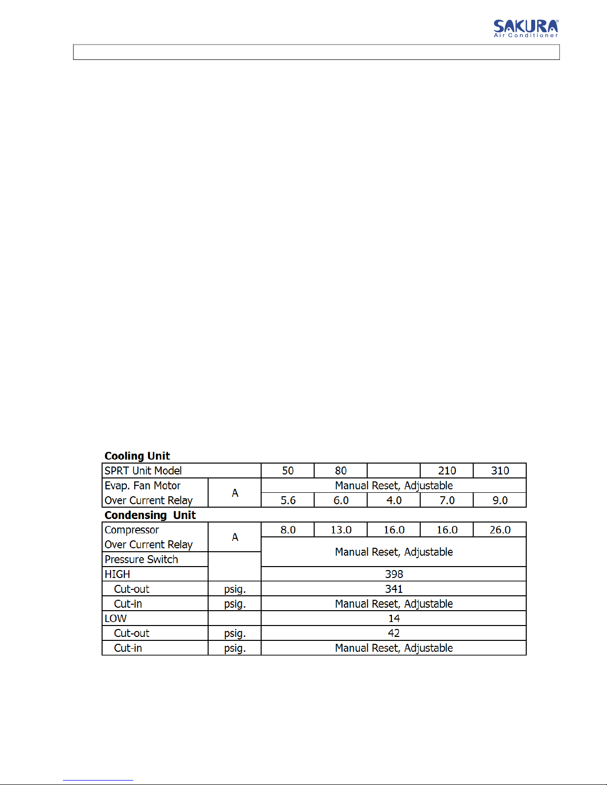
Compressor Protection - The compressor is protected with high pressure switch, an over current relay,
a crankcase heater, an internal thermostat, a reverse phase protection relay and a cycling protection timer
delay for compressor.
Fan motor - The evaporator fan motor and outdoor fan motor are protected with thermal over current
relay.
Condenser and Evaporator Coil - The coil have seamless Inner groove copper tubing mechanically
bonded to high efficiency. Each coil is factory tested at 400 psig. And easily accessible for service.
SAFETY PRECAUTIONS
Before installing the air conditioner unit, please read the following safety precautions carefully.
Warning
•Installation and maintenance should be preformed by qualified persons who are familiar
with local code and regulation, and experienced with this type of appliance.
•All field wiring must be installed in accordance with the national wiring regulation.
•Ensure that the rated voltage of the unit corresponds to that of the name plate before
commencing wiring work according to the wiring diagram.
•The unit must be GROUNDED to prevent possible hazard due to insulation failure.
•All electrical wiring must not touch the refrigerant piping, compressor or any moving parts
of the fan motors.
•Confirm that the unit has been switched OFF before installing or servicing the unit.
•Do not touch the compressor or refrigerant piping without wearing gloves.
Caution
Please take note of the following important points when installing.
-Do not install the unit where leakage of flammable gas may occur.
If gas leaks and accumulates at the surrounding of the unit, it may cause fire ignition.
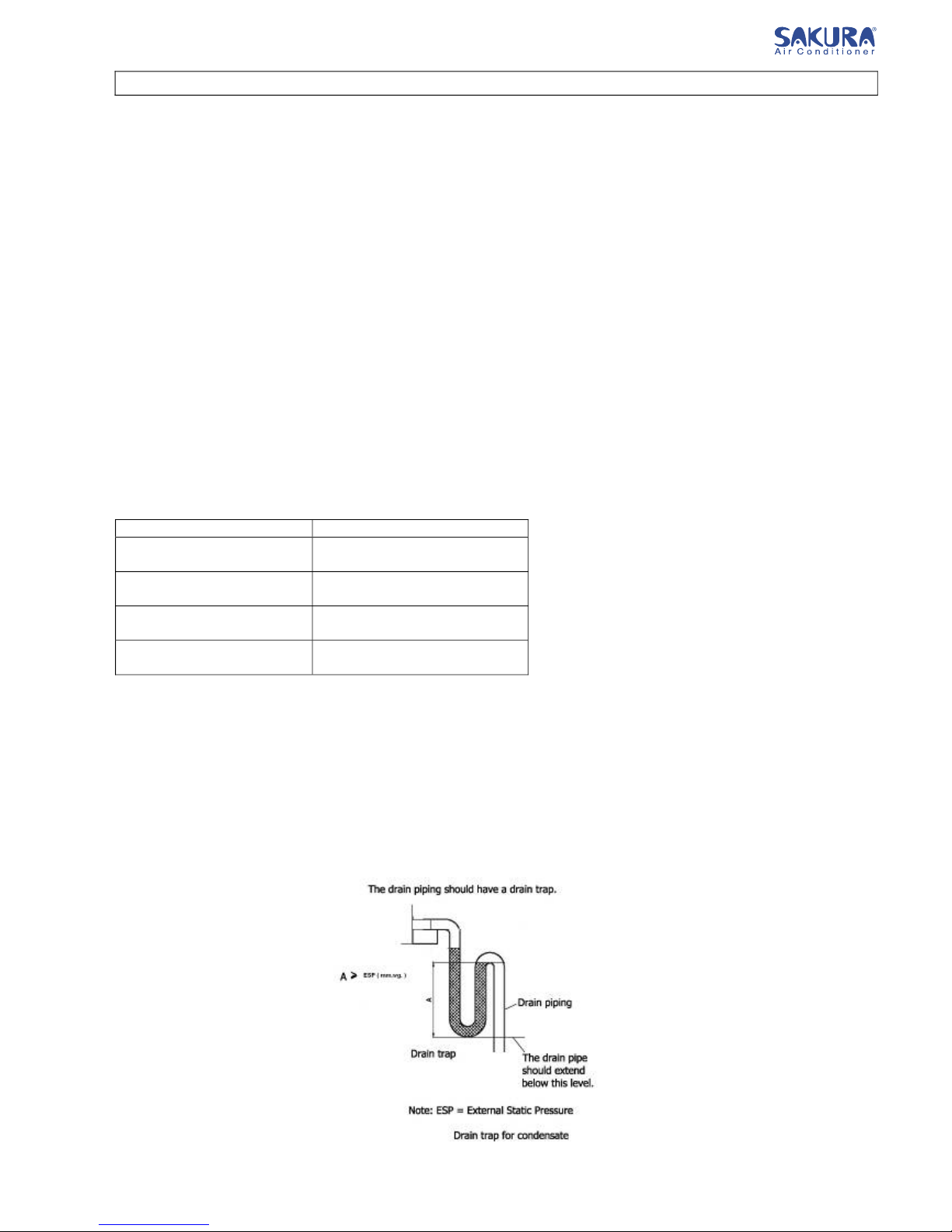
-Ensure that the drainage piping is connected properly.
If the drainage piping is not connected properly, it may cause water leakage.
-Do not overcharge the unit.
This unit is factory full charged. Overcharge will cause over-current or damage to the
compressor.
-Ensure that the unit panel is closed after service or installation.
Unsecured panels will cause the unit to operate noisily.
SAKURA - Total Air Conditioning Solution

SAKURA
100 / 105
2
GENERAL DATA
SAKURA - Total Air Conditioning Solution

3
OUTLINE AND DIMENSIONAL DATA
SAKURA - Total Air Conditioning Solution
SPRT 100 / 105

INSTALLATION OF THE UNIT
Location For Installation
Install the unit in such way that air distributed by the unit cannot be drawn in again (as in the case of
short circuit of discharge air). Allow sufficient space for maintenance around the unit.
Ensure that there are no obstructions of air flow into or out of the unit. Remove obstacles which blocks
air intake or discharge.
The location must be well ventilated, so that the unit can draw and distribute plenty of air.
A place capable of bearing the weight of the outdoor unit and isolating noise and vibration.
A place protected from direct sunlight. Otherwise use an awning for protection, if necessary.
A place where smooth drainage of rain water and water formed by defrosting is acceptable.
A place where the unit will not be buried in snow.
A place where air outlet port is not exposed to strong wind.
A place where the air discharge and operating sound level will not annoy the neighbors.
The location must not be susceptible to dust or oil mist.
Caution
If the condensing unit is operated in an atmosphere containing oils (including machine oils), salt
(coastal area), sulfide gas (near hot spring, oil refinery plant), such substances may lead to failure of
the unit.
Installation Clearance
4
SAKURA - Total Air Conditioning Solution

INSTALLATION OF THE UNIT
Unit Support
1. The figure shows the use of the roof curb available for mounting these units.
2. The curb should be sealed and fixed to the roof by weather stripping. A suggested means of sealing
the unit and roof curb as shown in the left.
Duct construction
-These units are equipped with supply and return air openings. Duct connection to the unit
should be made with duct flanges and secured directly to the air opining with flexible duct
connectors to avoid normal noise transmission.
-To prevent air leakage, all duct seams should be sealed.
-Ducts in the spaces that not air-conditioned, must be insulated.
-Ducts exposed to the outside must be weather proofed.
-Ducts that entering building through the roof, the entering should be sealed with weather
stripping to prevent the rain, sand, dust etc. from entering the building.
-Correct size of filter must be installed at the return air duct.
Refrigerant Charge
The units are full charged in Factory, no additional charge is necessary. The table below shows the
amount charged pre unit.
R-22 Refrigerant Charge amount
Model Charge per circuit (kgs.)
SPRT 80 1 x 4.5
1 x 5.6
SPRT 210 2 x 7.3
SPRT 310 2 x 10
Drain piping
-A 1” FPT condensate drain fitting is provided. The drain pipe can be led out at the front side.
-The drain pipe must be provided with a trap on the outside of the unit and also installed at an
incline for proper drainage, as shown in the right.
-To prevent condensate formation and leakage, provide the drain pipe with insulation to
safeguard against sweating.
-Upon completion of the piping work, check that there is no leakage and that the water drains
off properly.
-
5
SAKURA - Total Air Conditioning Solution
SPRT 100 / 105

Refrigerant Piping
DANGER
- Do not charge oxygen, acetylene or other flammable and poisonous gases into the refrigerant cycle when
performing the leakage test or an air-tight test. These types of gases are extremely dangerous and can
cause an explosion. It is recommended that compressed air, nitrogen or refrigerant be used for these types
of tests.
Evacuation and Refrigerant Charge
Tools and Instruments – Vacuum pump, High and Low Pressure Compound Gauge, refrigerant cylinder
with sufficient R-22, Weighing Scale, Refrigerating Oil (if required), Charging Hose
Preparation – Confirm the required amount of refrigerant, arrange piping connection work for evacuation
and refrigerant charge, as shown in fig. below.
Evacuation Procedures – Before charging refrigerant, the entire refrigeration cycle must be completely
evacuated and dehydrated. Connect the high pressure compound gauge to the high pressure check joint at
the compressor discharge side, and the low pressure compound gauge to the low pressure check joint at
the compressor suction side. Connect the vacuum pump to the service joint of the unit liquid stop valve
1. Operate the vacuum pump to perform primary evacuation of the piping and the unit.
2. Slowly open the liquid outlet stop valve and the gas inlet stop valve. Ensure that the unit is being
evacuated by checking both gauges.
3. Continue vacuum pump operation until the pressure indication on the gauges shows approximately
755 mmHg (0.67 Kpa).
4. Stop the vacuum pump, waited for approximately 5 minutes and confirm that the vacuum pressure
has not increased. Close the vacuum pump connection line.
Refrigerant Charge – change the vacuum pump with the refrigerant charging cylinder on the weighing
scale. 1. Purge air from the refrigerant charging cylinder connection line.
2. charge liquid refrigerant as required into the refrigerant cycle by weighing the refrigerant
charging cylinder.
3. After all evacuation and charging work, tighten the cap nuts for the unit stops valves.
6
SAKURA - Total Air Conditioning Solution

Control System & Electrical Wiring
Protection and Safety Control
Compressor Protection
All units are equipped with the following compressor protection system, in order to provide a perfect
guarding function for the compressor.
High Pressure Switch
Leading the pressures from the compressor discharge lines, this switch cuts out the compressor operation
when the discharge pressure exceeds the setting pressure.
Thermal Overload Relay
Equipped in the magnetic switch box, this relay quickly cuts out the compressor operation when the
current to the compressor exceeds the setting.
Reverse Phase Protection Relay
The reversal phase protection relay is equipped in the unit. If each phase R, S or T of the power source is
incorrectly connected, the compressor does not start due to the activation of the reversal phase protection
relay. Therefore, in order to check the correct wiring connection, the utilization of a phase sequence
indicator is recommended when the unit is started after installation of the units.
Crankcase Heater
Bound around the steel chamber for the hermetic compressor, this heater protects against oil foaming
during cold starting, as it is energized while the compressor is stopped.
Compressor Cycling Protection Timer Relay
Provide in control functions by delaying the compressor restarting period
Other Protection
Over current Relay for Evaporator Fan Motor
This manual reset type thermal over current relay for the evaporator fan motor interlocks system operation.
Safety and Control Device Setting
7
SAKURA - Total Air Conditioning Solution
100 / 105

8
SAKURA - Total Air Conditioning Solution

Control Function
9
SAKURA - Total Air Conditioning Solution

10
SAKURA - Total Air Conditioning Solution

11
SAKURA - Total Air Conditioning Solution

12
SAKURA - Total Air Conditioning Solution

13
SAKURA - Total Air Conditioning Solution

14
SAKURA - Total Air Conditioning Solution

15
SAKURA - Total Air Conditioning Solution

16
SAKURA - Total Air Conditioning Solution

17
SAKURA - Total Air Conditioning Solution

WIRE CONNECTION
- All electrical work must be carried out by qualified electrician and accordance with local supply
requirement and associated regulation.
- The unit is to be wired directly from an electrical distribution board either by a circuit breaker (preferred)
or HRC fuse.
- Fix the power supply wiring to control module. Connect control wiring to control terminal block through
the control box’s hole.
Note: Earth wiring must be connected.
Arrangements of control component and terminal block for controller are shown below.
No. Descriptions
1 Terminal Block for Main Supply
2 Terminal Block for Control
3 Terminal for Earth
4 Magnetic Contactor for Compressor
5 Magnetic Contactor for Evap. Fan Motor
6 Fuse
7 Reverse Phase Protection
8 Controller
Method for connecting electric wire
Before connecting the wire, consult the electric power company of jurisdiction.
The entire wiring diagram of unit.
Wiring connection to unit
Remove the panel and connect the units power supply wires to terminal block, as shown below.
Notes: For all electrical wiring must be comply with local electrical authority regulations.
8
1
2
3
6
5
4 7
18
SAKURA - Total Air Conditioning Solution

Electrical Wiring Diagram
19
SAKURA - Total Air Conditioning Solution
SPRT100 / 105 : 1 STAGE COOLING ONLY
Table of contents
Other Sakura Air Conditioner manuals
Popular Air Conditioner manuals by other brands

Soleus Air
Soleus Air KC-15U owner's manual

Fujitsu
Fujitsu General ASHH30KMTB Service manual

Bestron
Bestron AAC6000 instruction manual

Frigidaire
Frigidaire FAZ12ES2A installation instructions

Gree
Gree GKHD(12)ABND3A2AI Service manual

Mitsubishi Electric
Mitsubishi Electric Mr. Slim PUZ-M200YKA2.UK Service manual