Salda Ptouch User manual

Ragainės g. 100, LT-78109 Šiauliai, Lithuania
Tel. (+370 41) 540415
Fax. (+370 41) 540417
www.salda.lt
Art.-no. PRGPU081
•Remotecontrolpanel
Ptouch
Servicemanual
PRV
PRV_P0098_AZ_0001

1GENERALINFORMATION...................................................................................................... 3
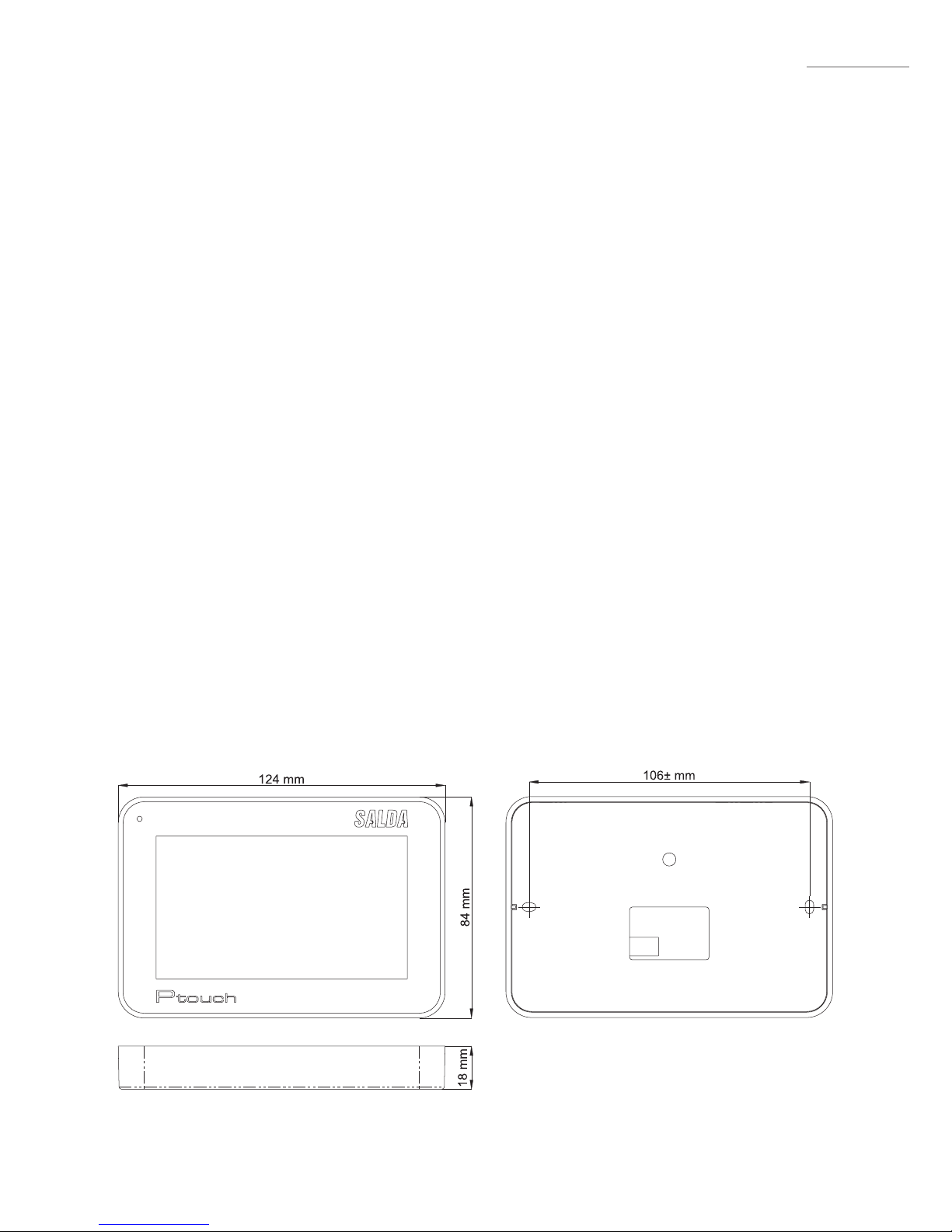
2DIMENSIONS............................................................................................................................. 3
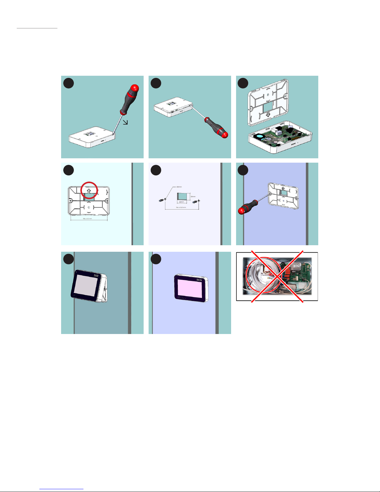
3INSTALLATION.......................................................................................................................... 4
4SERVICE........................................................................................................................................ 5
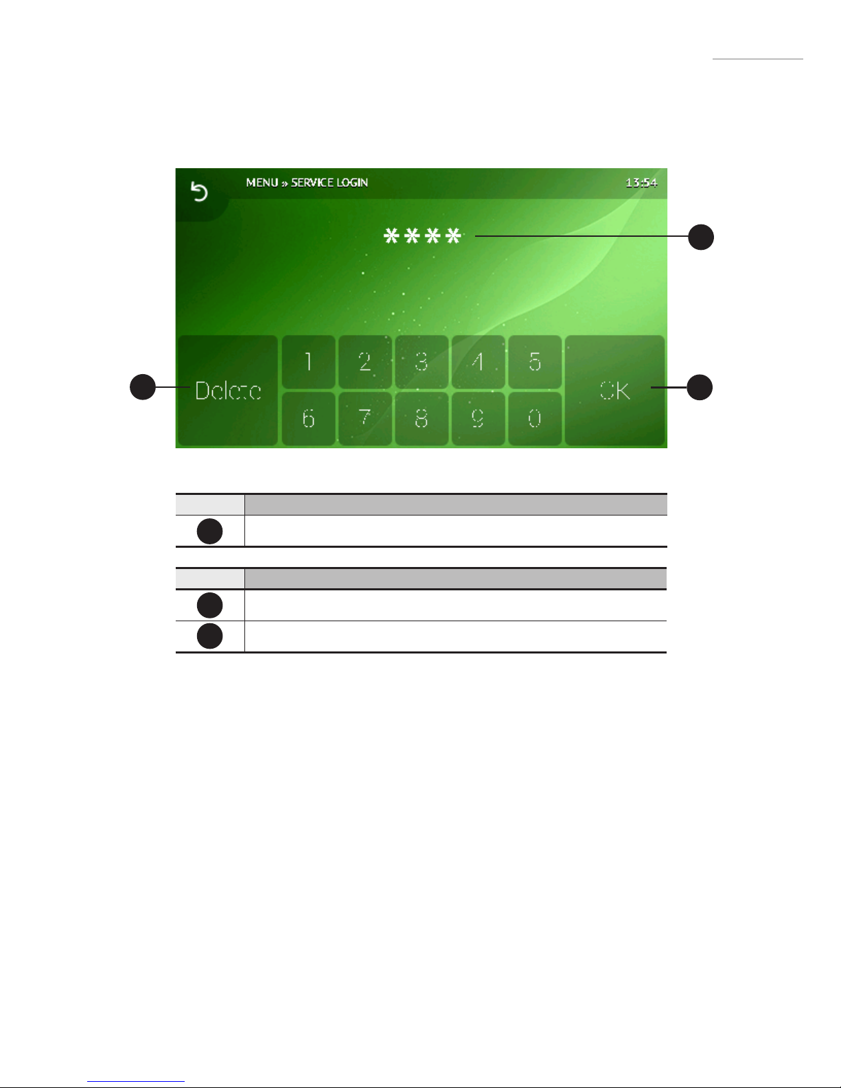
4.1 Service login ...................................................................................................................... 5
4.2 Service menu .................................................................................................................... 6
4.3 Ventilation mode settings ............................................................................................ 7
4.4 Cooling settings ............................................................................................................... 8
4.5 Fan settings menu ........................................................................................................... 8
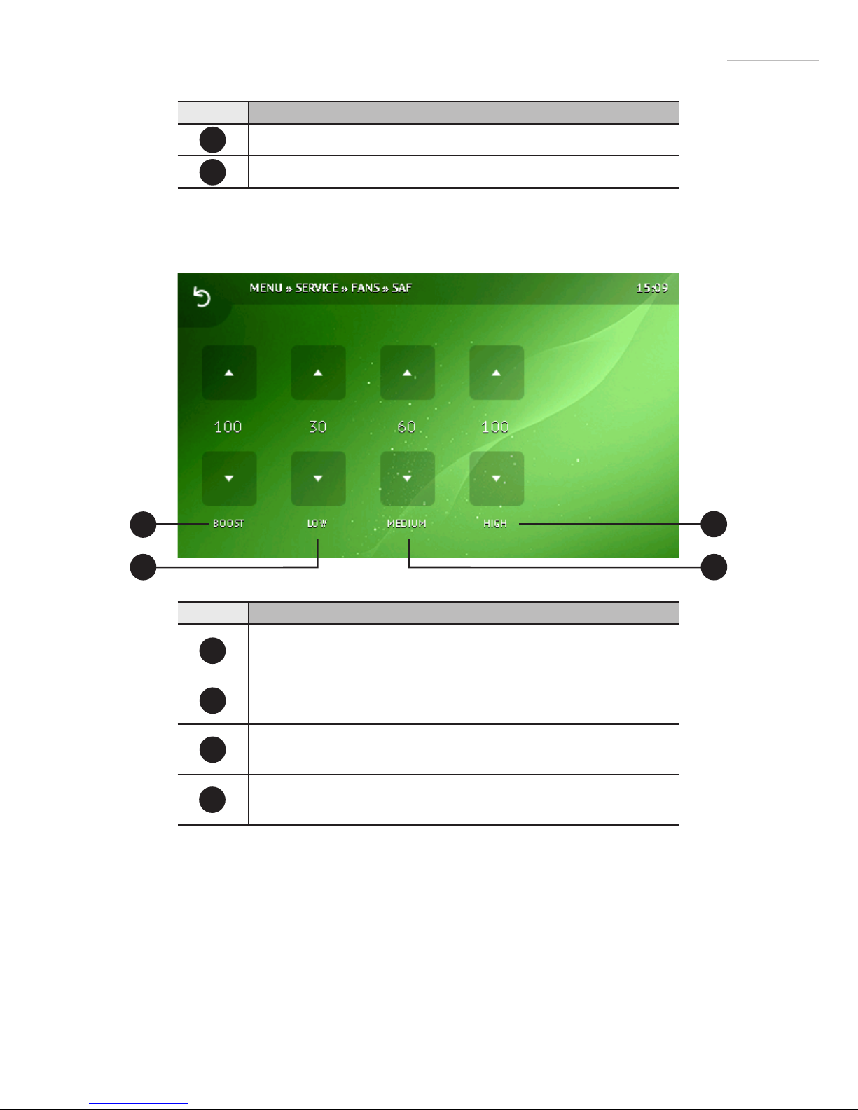
4.5.1 Air supply fan settings ......................................................................................... 9
4.5.2 Air extraction fan settings ................................................................................ 10
4.6 Modbus interface settings ......................................................................................... 11
4.7 System settings ...............................................................................................................12
4.8 Water heater settings ................................................................................................... 13
4.9 Ventilation settings ........................................................................................................14
4.10 PI controller settings................................................................................................... 15
4.10.1 PID adjustment screen ................................................................................... 16
4.11 Pressure sensor settings ............................................................................................17
4.12 CO2 sensor settings ....................................................................................................17
4.13 Anti-freezing settings .................................................................................................18
4.14 Air lter settings .......................................................................................................... 19
4.15 Factory settings ........................................................................................................... 19
TABLE OF
CONTENTS

3
GENERAL INFORMATION
1
Ptouchremotecontrolpanelisdesignedfor:
• SALDA ventilation units and other devices based on PRV, MCB or ECO controllers;
• Modbus-controlled devices.
Remote control panels guarantee optimal comfort of operation, monitoring, maintenance and service. All
operations can be performed using remote panel, which displays the status of the system, fault reports
and service settings.
Features:
• Simple use;
• Surface mounted;
• 4.3 touch-screen;
• Display of functions and set points;
• Acoustic response to touch;
• Maximum fan speed setting for limited time period (BOOST);
• Blocking (locking) - protection from children;
• User menu for fan speed, mode, status, CO2 control settings.
Packageincludes:
• 1x Ptouch control panel;
• 1x Cable;
• 1x Manual;
• 2x Fastening elements (screw 3,9 x 25 DIN 7981 – 2 pcs nylon plug 5x25 – 2 pcs, hammered steel plug
12x30 – 2 pcs).
DIMENSIONS 2
EN

4
3 Ptouchinstallationonaplaster-boardwall:
Ptouchinstallationonaplaster-boardwall:
1-2Turn over the panel. Use a screwdriver to lift the cover as shown in g.2.
3Take the cover apart.
4Put it at desired location on the wall. The arrow must point upwards. Mark the positions of mounting
holes (distance center-to-center is 106 ± 0.5 mm). Also mark the position of the square hole for the cable
(30 x 20 mm).
5Drill two 5 mm holes at the marked positions for nylon plugs and the hole throughout the wall to install
the cable. Insert the nylon plugs.
NOTE:Youcanusespecialmetalplugs(included)insteadofnylonones.
6Use included 2,9x16 DIN7981C screws and mount the panel to the wall as indicated in g. 6.
Connect the included cable to the panel and pass another end of the cable through the square hole in
the wall.
7-8Put the panel on the mounting bracket by aligning the upper identations. Then push the lower part
of the panel.
IMPORTANT:Donotforgettoconnectthecablebeforeattachingthepanel.
1
4
7
IMPORTANT: IT IS FORBID-
DENtoleavetheremaining
remotecontroller’scablein
theAHU’scontrolbox!
2
5
8
3
6
EN

5
B2
B1
I1
4.1Servicelogin
SERVICE 4
EN
Number Function
Entered code (masked) 4444
Number Function
Clear last entered digit
Conrm entered code
I1
B1
B2

6
4
EN
4.2Servicemenu
B2
B10
B6
B1
B9
B5
B13
B3
B11
B12
B4
B7
B8
Number Function
Ventilation mode settings
Cooling settings
Fan settings
Modbus interface settings
System settings
Water heater settings
Ventilation settings
PI controller settings
Pressure sensor settings
CO2 sensor settings
B1
B4
B2
B3
B5
B6
B7
B8
B9
B10

7
4
EN
4.3Ventilationmodesettings
Anti-freezing settings
Filter settings
Factory settings
B11
B12
F1
F2
F4
F3
Number Function
Ventilation mode:
Supply: maintain supplied air temperature;
Room: maintain extracted air temperature;
ByOutDoor: ventilation is controlled by supplied or extracted air tem-
perature depending on OutDoor T.C setting. If outdoor temperature
exceeds OutDoor T.C setting, ventilation is controlled by extracted
air temperature. If outdoor temperature is lower than OutDoor T.C -
ventilation is controlled by supplied air temperature.
Minimum allowed supplied air temperature.
Range: [12-24 °C]
Maximum allowed supplied air temperature.
Range: [25-40 °C]
Summer – winter temperature selection.
Range: [10-30 °C]
F1
F2
F3
F4
B13

8
2.4Coolingsettings
4.5Fansettingsmenu
4
EN
Number Function
Minimum allowed supplied air temperature when cooling.
Range: [0-15 °C]
Freon-based cooling enabling temperature.
Range: [12-24 °C]
Freon-based cooling disabling temperature.
Range: [25-40 °C]
Minimum outside temperature to allow cooling.
Range: [10-30 °C]
F1
F4
F2
F3
F1
F2 F3
B1
F4
B2

9
4
EN
Number Function
Supply fan speed for Boost function.
Range: [0-100 %]
Supply fan speed for 1st mode.
Range: [0-100 %]
Supply fan speed for 2nd mode.
Range: [0-100 %]
Supply fan speed for 3rd mode.
Range: [0-100 %]
F1
F4
F2
F3
Number Function
Air supply fan settings
Air extraction fan settings
B1
B2
4.5.1Airsupplyfansettings
F1
F2
F4
F3

10
4.5.2Airextractionfansettings
4
EN
Number Function
Extract fan speed for Boost function.
Range: [0-100 %]
Extract fan speed for 1st mode.
Range: [0-100 %]
Extract fan speed for 2nd mode.
Range: [0-100 %]
Extract fan speed for 3rd mode.
Range: [0-100 %]
F1
F4
F2
F3
F1
F2
F4
F3

11
4
EN
Number Function
Parity:
None;
Odd;
Even.
Baud rate:
2400; 4800; 9600; 19200; 38400.
Stop bits:
1 stop bit;
2 stop bits.
AHU Control unit Modbus address.
Range: [1-247]
F1
F4
F2
F3
4.6Modbusinterfacesettings
F1
F2
F4
F3

12
4
EN
4.7Systemsettings
Number Function
Heater type:
E_On/O: Relay-controlled electrical heater;
E_0_10: 0-10V signal-controlled electrical heater;
E_ESKM: Triac-controlled electrical heater;
W_VAL+-: 3-way valve actuator for water heating.
W_0_10: 0-10V signal-controlled valve actuator for water heating.
Heat exchanger type:
R_0_10: 0-10V signal-controlled rotary heat exchanger;
R_On/O: Relay-controlled rotary heat exchanger;
B_0_10: 0-10V signal-controlled bypass valve for plate heat
exchanger;
B_DMP: 3-way bypass valve actuator for plate heat exchanger.
AHU type:
TK: Air supply chamber;
RHEC: Re-cooperator with heat exchanger control;
RHEC: Re-cooperator without heat exchanger control;
Fan type:
EC: 0-10V signal-controlled EC motor;
AC: AC motor controlled using three xed voltages;
F1
F4
F2
F3
F1
F2
F4
F3

13
4.8Waterheatersettings 4
EN
F1
F2
F4
F3
Number Function
Threshold to force an increase of a returning water temperature.
Threshold to stop fans.
Maximum idle water pump operation (when there is no need for
heating).
Range: [10-30 minutes]
Interval of water pump prophylactic. In Pump-stopped state, pump
is exercised for „Pump stop minutes“ period.
Range: [0-5 h]
F1
F4
F2
F3

14
4
EN
4.9Ventilationsettings
Number Function
Supplied air fan indication:
Percent: indicate fan state in %;
Pressure: indicate fan state in Pa.
Extracted air fan indication:
Percent: indicate fan state in %;
Pressure: indicate fan state in Pa;
SAF + Pressure: indicate fan state as dierence from supplied air
pressure (in Pa).
Use of extracted air CO2 sensor:
On;
O.
F1
F2
F3
F1
F2 F3

15
EN
4
4.10PIcontrollersettings
B2
B6
B1
B5
B3
B4
Number Function
Adjustments of PI controller used by system to react to heating or
cooling.
Adjustments of PI controller used in the mode of maintaining ex-
tracted air temperature.
Electrical heater PI controller adjustments.
Adjustments of PI controller for bypass valve or rotor heat ex-changer.
Cooler PI controller adjustments.
Pre-heater PI controller adjustments.
B1
B4
B2
B3
B5
B6

16
4
EN
4.10.1PIDadjustmentscreen
Number Function
Proportional coecient.
Range: [0-1000]
Integral coecient.
Range: [0-1000]
F1
F2
F1
F2
Number Function
Current setting indication
I1
I1
NOTE: This screen is applicable for all PID controller adjustments.

17
EN
4.11Pressuresensorsettings
Number Function
Pressure corresponding to 0V input signal.
Range: [0-2000 Pa]
Pressure corresponding to 10V input signal.
Range: [0-2000 Pa]
F1
F2
F1
F2
4.12CO2sensorsettings
F1
F2 F3
4

18
4
EN
Number Function
CO2 level (in ppm) at minimum voltage (0 VDC).
Range: [0-2000 ppm]
CO2 level (in ppm) at maximum voltage (10 VDC).
Range: [0-2000 ppm]
Voltage at 100 ppm CO2 level
Range: [0-10 V*10]
F1
F2
F3
4.13Anti-freezingsettings
Number Function
Anti-freeze protection algorithm:
DewP/PlateT: Dew point and heat exchanger surface temperature
calculation-based;
Toutside: Outside temperature based (DIBT);
TEsetpoint: Exhausted air temperature based;
Heat exchanger anti-freezing diagram-based;
Heat exchanger anti-freezing diagram-based.
Air supply fan speed decrease:
On: allowed;
O: forbidden.
Action on likely-freezing condition:
On: bypass valve is allowed to be opened or rotor is allowed to
be stopped;
O: bypass valve is not allowed to be opened or rotor is not
allowed to be stopped.
F1
F2
F3
F1
F2
F4
F3

19
EN
4
Number Function
Working hours till reminder to replace air lters.
Number Function
F1
F1
F4
Fault alert if too-cold air is supplied longer than allowed period:
On: alert will be shown;
O: alert will be suppressed.
4.14Airltersettings
4.15Factorysettings
F1
F1
Other manuals for Ptouch
3
Table of contents
Other Salda Remote Control manuals