Salto CONLAN CM1000EMV User manual

Publications of CONLAN ApS are protected by copyright and all rights are reserved.
CONLAN ApS publications may not be reproduced in any form or by any means without written permission from the copyright owner
CM1000 EMV
USER MANUAL
CM1000 EMV
CM1000 EMV is a exible keypad and Mifare reader in one unit for
many different applications. This device supports EMV (Europay,
MasterCard, and Visa) cards or mobile wallets as access control
devices (not payment transactions supported).
Mykey - Art. Nr: 480040 (black), 480042 (white)
Classic - Art. Nr.: 482040 (black), 482041 (white)
www.conlan.eu

USER MANUAL - CM1000-ENG-09-22
CONTENT
1. Installation
2. Access
2.1 Using the device
3. Fixed user PIN codes management
3.1. Adding user PIN codes
3.2 Adding NFC tags
3.3 Deleting user PIN codes and NFC tags
3.4 Assigning an Output behavior for a user
3.5 Smart enroll
4. Configuration
4.1 Change User Conguration code
4.2 Change Service Conguration code
4.3 LED’s and Buzzer Feedback Conguration
4.4 Outputs Conguration
4.4.1 Conguring Output activation time
4.4.2 Conguring Output activation ank
4.5 Special functions
4.5.1 Service Conguration Code Timeout
4.5.2 Change User Conguration Code without Service
Conguration Code
4.5.3 Mute
4.5.4 exBuzzer Function
4.5.5 Software Enable High Security Function
4.5.6 Bell Key Function
4.6 High Security
4.7 Backup Card
4.7.1 Cloning
4.7.2 Loading
5. Hardware factory reset
6. REX Input
7. Technical specifications
Page 3
Page 3
Page 3
Page 4
Page 5
Page 5
Page 6
Page 7
Page 9
Page 10
Page 10
Page 11
Page 12
Page 13
Page 14
Page 15
Page 17
Page 17
Page 17
Page 18
Page 18
Page 18
Page 18
Page 19
Page 19
Page 20
Page 20
Page 21
Page 22
Page 22

3
USER MANUAL - CM1000-ENG-09-22
USER MANUAL -CM1000-ENG-09-22
2.1. Using the device
User PIN’s and NFC tags ID’s are allocated in the internal device memory. The CM1000 can retain
up to 190 xed codes from 1 to 8 digits long or NFC tag ID’s. Each individual user has their own
PIN code or NFC tag to operate the lock. This permits also to share one lock between different
users.
1234 is a default xed PIN code congured at position 1 under fabrication and can be used to
test the device. Check ‘3. Fixed User PIN Codes and NFC Tags Management’ section at page 4
to manage the xed PIN’s and NFC Tags.
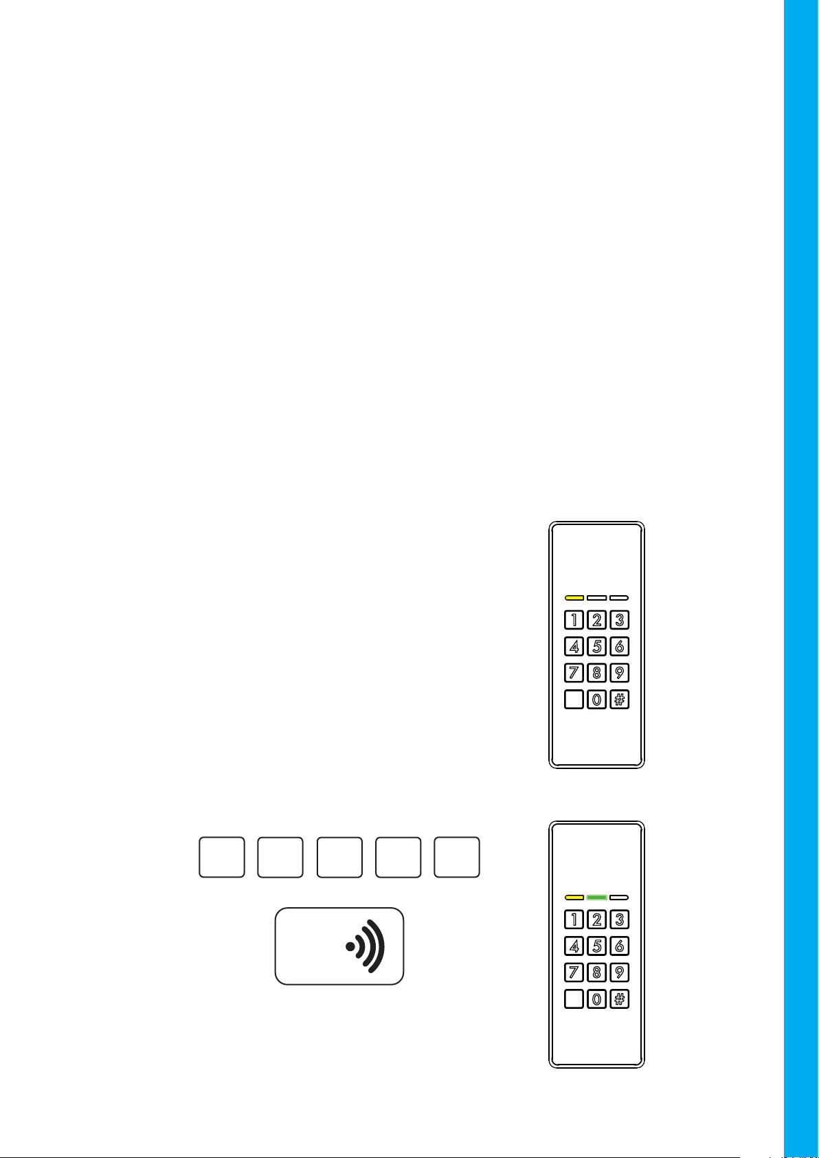
2. ACCESS
The keypad is totally Stand Alone and can grant access to open a lock by inserting a custom user
PIN code or swiping a NFC tag or EMV (Europay, MasterCard, and Visa) cards.
1. INSTALLATION
For instructions on the installation, please check the installation guide.
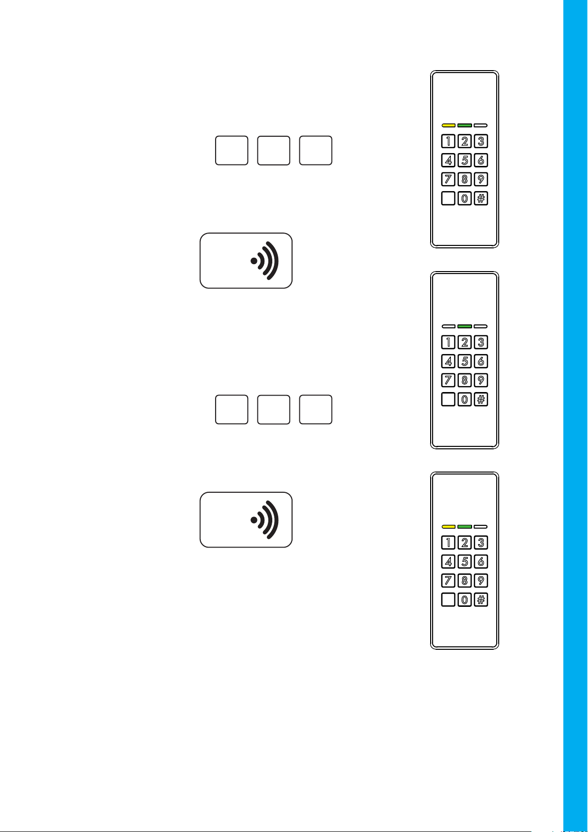
Upon entering a VALID user PIN code, or swiping
a VALID NFC tag, a conrmation beep will sound
and the green LED will blink one time.
Output2 is activated.
#
32 4
1
Example:
Opening and Closing
OR
NFC
Swiping a valid
NFC card
The yellow light is always ON in idle
state, the keypad is waiting for a user
interaction.
Back-lights are OFF as default, but
turns on when a key is touched.
Idle State

4
USER MANUAL - CM1000-ENG-09-22
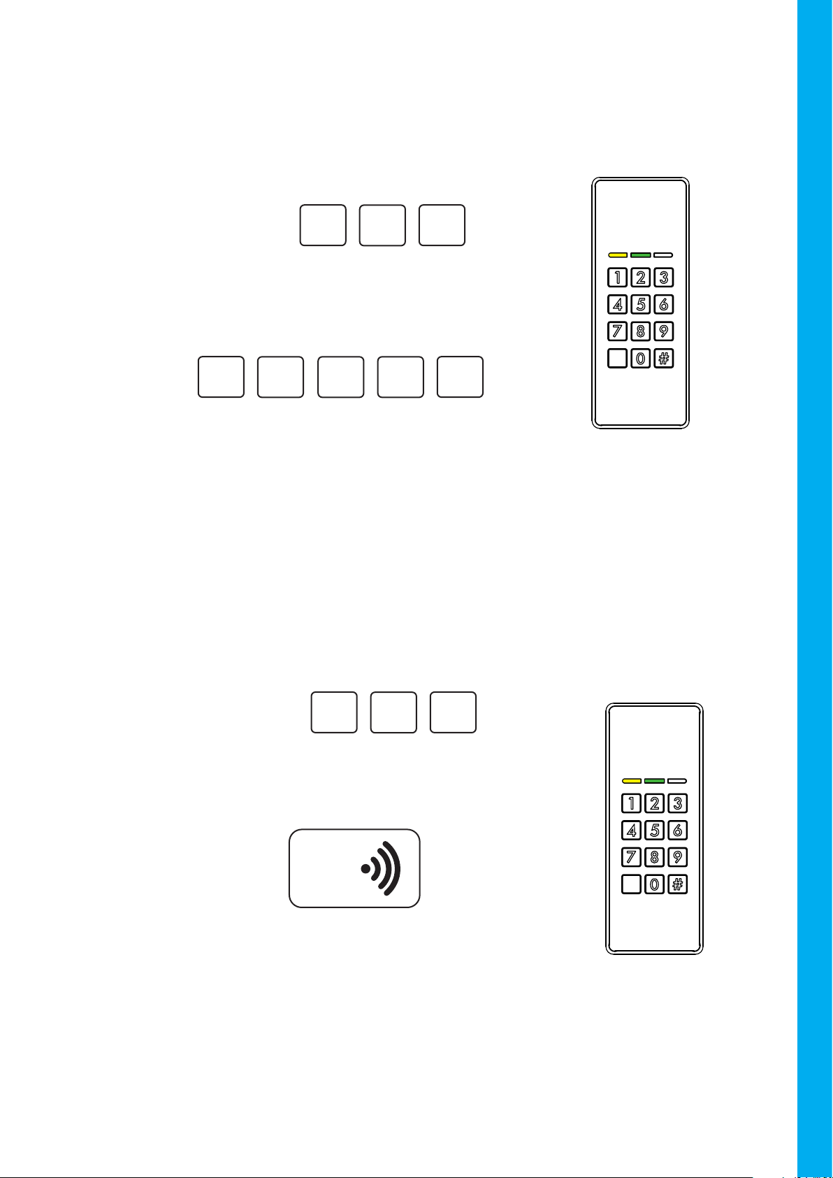
The next sections uses Juan as example to add and delete xed PIN codes on the device.
Position User PIN
1 Carlos 148954
17 Torbjörn 94830132
23 Juan 1111
Example of user tracking:
Example:
3. FIXED USER PIN CODES AND NFC TAGS MANAGEMENT
User PIN codes and NFC tags can be changed, added, and deleted. Each user PIN code or NFC tag
is stored in a specic addressed internal memory position (from 1 to 190). We recommend to keep
a record of the position numbers and user names to future management.
To add or delete user PIN codes or NFC tags, is necessary to access the User Conguration Menu:
After 4 successive wrong tries, the keypad will lockout for 60 seconds.
In case of WRONG code inserted or swiping an
INVALID NFC tag, a rejection beep will sound
and the Red LED will blink one time.
#
00 0
0
Example:
Wrong Code
NFC
OR
Swiping a wrong
NFC card
1#
7 1
4
Insert the User Conguration Code
(4711 is factory default)
The yellow LED will turn OFF and the
green LED will turn ON.
The keypad is ready to add or delete xed
user PIN’s.
User Conguration Menu
Enter:

5
USER MANUAL - CM1000-ENG-09-22
USER MANUAL -CM1000-ENG-09-22
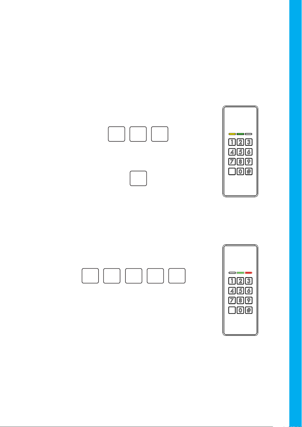
3.2 Adding user NFC tags
3.1 Adding user PIN codes
Note that the rst 9 positions must always be inserted as one digit numbers, without a zero ‘0’
in front. It means, insert ‘1’ not ’01’, insert ‘2’ not ‘02’, etc. Numbers that starts with zero ‘0’ are
reserved to Special functions (check 4.5 Special Functions, page 17).
All positions can be overwritten, so be aware to keep a
register of all the congured PIN codes and their positions.
1#
1 1
1
Example:
If a valid position is inserted, the yellow and green LED’s
will light solid until the xed user PIN code is entered. The
xed user PIN must be a number of 1 to 8 digits.
#
3
2
To add users, rst insert a position to place the new PIN
code (between 1 and 190).
Example:
A conrmation beep will sound, once if a normal Mifare
NFC tag is registered, twice if a EMV (Europay, Master-
Card, and Visa) card is registered.
All positions can be overwritten, so be aware to keep a
register of all the congured PIN codes and their positions.
If a valid position is inserted, the yellow and green LED’s
will light solid until a valid NFC card is swiped in front of
the reader.
#
3
2
To add users, rst insert a position to place the new NFC
tag (between 1 and 190).
Example:
NFC
Swiping a valid
NFC card

6
USER MANUAL - CM1000-ENG-09-22
3.3 Deleting user PIN codes and NFC tags
Deletion is a simple process that can be performed just by knowing the PIN code(s) or NFC tag(s)
position to be deleted.
If a valid position is inserted, the yellow and green LED’s will
light solid until the deletion is conrmed. Push # to cormm
the deletion
Insert the position of the user PIN or NFC tag that you want
to delete (a number between 1 and 190).
Deleting a specic PIN code or NFC tag
#
3
2
Example:
#
Enter:
The keypad go back to User Conguration Menu and is ready
to perform another user PIN handling action.
The red and green LED’s will blink. All the stored PIN codes
are now deleted.
Insert 2500, to clear the user PIN’s memory on the device.
Deleting all user PIN codes and NFC tags
0#
5 0
2
Enter:
The keypad go back to User Conguration Menu and is ready
to perform another user PIN handling action.

7
USER MANUAL - CM1000-ENG-09-22
USER MANUAL -CM1000-ENG-09-22
3.4 Assigning an Output behavior for a user
When adding users to the device, it is possible to specify the corresponding Output be-
havior for every specic PIN code or NFC tag.
There are four congurable Output modes:
Toggling Mode: The inserted PIN code or NFC tag, changes the corresponding Output
state to Active and remains in this state until a new or the same valid PIN code or NFC
tag, congured in Toggling Mode, is used again; the Output then changes state to Inac-
tive. The Output toggles its state every time a PIN code or NFC tag congured as Toggling
Mode is used.
To congure a PIN code or NFC tag with this Output Mode, add the same PIN code or
NFC tag at the same position twice.
Switch Only to Active Mode: The inserted PIN code or NFC tag, changes the corre-
sponding Output state to Active and remains in this state.
To congure a PIN code or NFC tag with this Output Mode, add the same PIN code or
NFC tag at the same position for three times.
Normal Mode: The inserted PIN code or NFC tag, changes the corresponding Output
state to Active and remains in this state until the congured Output Timeout (4.4.1 Cong-
uring Output activation time, page 13) expires. The output then changes its state to Inac-
tive.
All user PIN codes or NFC tags are congured in Normal Mode as default.
Switch Only to Inactive Mode: The inserted PIN code or NFC tag, changes the corre-
sponding Output state to Inactive and remains in this state.
To congure a PIN code or NFC tag with this Output Mode, add the same PIN code or
NFC tag at the same position four times.

8
USER MANUAL - CM1000-ENG-09-22
A conrmation beep will sound, once if a normal Mifare
NFC tag is registered, twice if a EMV (Europay, Master-
Card, and Visa) card is registered.
The keypad go back to User Conguration Menu.
If a valid position is inserted, the yellow and green LED’s
will light solid until a valid NFC card is swiped in front of
the reader.
#
3
2
Example: Conguring a NFC tag to Toggling Mode.
To add users, rst insert a position to place the new NFC
tag (between 1 and 190).
Example:
NFC
Swiping a valid
NFC card
If a valid position is inserted, the yellow and green LED’s
will light solid until a valid NFC card is swiped in front of
the reader.
#
3
2
Insert the same position again.
Example:
NFC
Swiping the same
valid NFC card
again
A conrmation beep will sound, once if a normal Mifare
NFC tag is registered, twice if a EMV (Europay, Master-
Card, and Visa) card is registered.
The keypad go back to User Conguration Menu.
Now, this NFC card Toggles the corresponding Output
every time it is used.

9
USER MANUAL - CM1000-ENG-09-22
USER MANUAL -CM1000-ENG-09-22
3.5 Smart enroll
This function can help when a large number of NFC tags or PIN codes needs to be registered at
the same time.
Smart Enroll allows the PIN code or NFC card registration without specify a memory position for
every enrollment. It means, just an initial position is needed and all the subsequent registrations
are placed automatically at the consecutive next memory position.
The green LED blinks once, the NFC card is registered at
position 23.
If a valid position is inserted, only the yellow LED starts
to blink until a user PIN code is entered or a NFC card
is swiped (the xed user PIN must be a number of 1 to 8
digits).
#
3
2
The yellow LED blinks and the green LED remains ON, the
device is waiting for a start position.
To start users enrolling, rst insert a start position to place
the rst PIN code or NFC tag (between 1 and 190).
Example:
Enter: 5
0#
NFC
Example: Swiping
a valid NFC card
NFC
Example: Swiping
another valid NFC
card
NFC
Example: Swiping
another valid NFC
card
The green LED blinks once, the NFC card is registered at
position 25.
.
.
.
The green LED blinks once, the NFC card is registered at
position 24.

10
USER MANUAL - CM1000-ENG-09-22
4.1 Change User Configuration Code
Once in Service Conguration Menu, the following actions can be performed:
It is possible to access the Service Configuration Menu withing the first
60 seconds after the device has been powered up (connected to a power
supply). After this time, the Service Configuration Menu is inaccessible.
4. CONFIGURATION
The service conguration code is used to authenticate and access the conguration menu,
which is needed to congure the CM1000.
Just after the device has been powered up, insert the Service Con-
guration Code (12347890 is factory default)
The green LED will turn ON.
The keypad is now ready to be congured.
Service Conguration Menu
9#
8 0
7
32 4
1
Enter:
2#
3 1
4
The User Conguration Code has been changed. The keypad
go back to User Conguration Menu and is ready to perform
another Service Conguration action.
The yellow and green LED will light solid. The keypad is
ready to receive a new User Conguration Code. Insert a
code that is between 1 to 8 digits.
Example:
Enter: 0
0#

11
USER MANUAL - CM1000-ENG-09-22
USER MANUAL -CM1000-ENG-09-22
4.2 Change Service Configuration Code
Example:
Example:
The Service Conguration Code has been changed. The keypad go
back to User Conguration Menu and is ready to perform another Ser-
vice Conguration action.
9#
8 0
7
32 4
1
The yellow and green LED will blink until the new Service Conguration
Code is inserted again to conrm the action.
Insert the same code again.
9#
8 0
7
32 4
1
The yellow and green LED will turn ON. The keypad is ready to receive
a new Service Conguration Code. Insert a code that is between 1 to
8 digits.
Enter: 1
0#

12
USER MANUAL - CM1000-ENG-09-22
Light indications can be customized for the following three device states:
4.3 LED’s and Buzzer Feedback Configuration
Idle: Device normal state, nothing to perform, waiting for user interaction. The LED(s) remains
in this state until a user interaction is detected.
Access Granted : Feedback when a valid PIN code or NFC tag is used to grant access. The
LED(s) and buzzer audio indication, remains in this state as long as the Output is Active.
Key Touched: Feedback when a key is touched. Buzzer audio indication and LED(s) remains
in this state (blinks) for 500ms.
To customize a selected state, use the keys 1, 2 and 3 to turn ON or OFF the Yellow, Green and Red
LED’s respectively. Besides, the buzzer behavior can also be customized for the Access Granted
and Key Touched states by using the key 0, if the buzzer is not muted in this state, a constant beep
can be heard.
#
Enter:
The LED indications has been changed. The keypad go back to LED’s and Buzzer
Feedback Conguration menu, and is ready to chose another state to be customized.
All three LEDs will turn ON until a device state to congure
is selected:
To customiz the LED indications rst insert:
Enter: 2
0#
Enter: 1 # to congure Idle user feedback
Enter: 2 # to congure Access Granted user
feedback
Enter: 3 # to congure Key Touched feed-
back
The device shows the selected state LED’s feedback, and
for Access Granted and Key Touched states, also the
Buzzer feedback by a constant beep if it’s not muted.
Now it is posible to customize the state feedback.
LED’s
Values for LED
selection: 1 2 3 0
Use the corresponding key to turn ON or OFF the wanted LED or Buzzer
When the customization is done,
push # to save the conguration

13
USER MANUAL - CM1000-ENG-09-22
USER MANUAL -CM1000-ENG-09-22
4.4 Outputs Configuration
When a valid PIN or NFC tag is used, the corresponding Output (Output1 or Output2) is Activated
(GND) for a dened period of time (5 seconds as default). The Output assigned for a user is de-
ned by a User Output Assignation Array with 190 available positions.
Positions 1 to 100
for Output2
Positions 101 to 150
for Output1
Positions 151 to 190
for both, Output1
and Output2
What this User Output Assignation Array means is:
• If a user PIN or NFC tag is registered in a position between 1 and 100 (as default), Out-
put 2 is activated every time this PIN or NFC tag is used to grant access.
• If a user PIN or NFC tag is registered in a position between 101 and 150 (as default),
Output 1 is activated every time this PIN or NFC tag is used to grant access.
• If a user PIN or NFC tag is registered in a position between 151 and 190 (as default),
both, Output 1 and Output 2 are activated as the same time every time this PIN or NFC
tag is used to grant access.
There are 3 congurable parameters for an output:
Activation time: 5 seconds as default, but congurable up to 61 hours.
Activation Flank: GND as default, the ‘polarity’ which the output changes to when active.
There are only two options:
Idle State Active State
Normal Floating (not connected) GND
Inverted GND Floating (not connected)
User Output Assignation Array: As default this array looks like follows:
To manage all those congurations:
The green and red LED’s will light solid until a parameter to
be congured is inserted
Enter: 3
0#

14
USER MANUAL - CM1000-ENG-09-22
4.4.1 Configuring Output activation time
#
0
Example,
Conguring 0 hours
Activation Time:
The selected Output is congured to remain Active for 15
seconds when a valid PIN code or NFC tag is used to grant
access.
The keypad go back to Outputs Conguration Menu and is
ready to perform another action.
Enter: 1 #
Enter: 2 #
For Output 1
For Output 2
OR
Example,
Conguring 15 seconds
Activation Time: #
5
1
The yellow LED will turn ON and remain in this state until a
time in hours, from 0 to 60, is inserted.
#
0
Example,
Conguring 0 minutes
Activation Time:
The green LED will turn ON and remain in this state until a
time in minutes, from 0 to 60, is inserted.
The red LED will turn ON and remain in this state until a time
in seconds, from 0 to 60, is inserted.

15
USER MANUAL - CM1000-ENG-09-22
USER MANUAL -CM1000-ENG-09-22
4.4.2 Configuring Output activation flank
4.4.3 Configuring User Output Assignation Array
This function uses a User Output Assignation Array to assign a dened Output to a group of user
PIN’s or NFC tags.
We assume the User Output Assignation Array is separated in user groups by two Splitters:
• Splitter1: All users registered at positions behind it, inclusive the Splitter1 itself activates Out-
put2.
• Splitter2: All users registered at positions behind it, inclusive the Splitter2 itself, and back to
the Splitter1, activates Output1. Besides, all users registered at positions in front of the Splitter2
up to the last position of the array (position 190), activates both, Output1 and Output2, at the
same time.
In this example, all users from 0 to 100 activates Output2, all users from 101 to 150 activates Out-
put1 and all users between 151 and 190 activates both, Output1 and Output2.
Note that Splitter2 value must always be greater than Splitter1 value, otherwise, the conguration
will be rejected and an error beep will sound.
Output2 Output1 Output1 and Output2
Splitter1 100 Splitter2 150
0
190
Enter: 5 #
Enter: 1
Enter: 2
To toggle Output1
Activation Flank
OR
THEN
To toggle Output2
Activation Flank
Normal Inverted
The keypad go back to Outputs Conguration Menu and is
ready to perform another action.
#
Enter: When the customization is done
to save the conguration

16
USER MANUAL - CM1000-ENG-09-22
Enter: 3 # For Splitter 2
Example: Conguring users from 1 to 50 to activate Output2, users
from 51 to 100 to activate output1 and the remaining positions to
activate both Output1 and Output2:
Enter: 4 # For Splitter 1
The green LED will turn ON and remains in this
state until Splitter1 position is inserted.
Example: 50 #
The Splitter1 has been set. The keypad go back
to Outputs Conguration menu, the red and green
LED’s turns ON and is ready to chose another pa-
rameter to be customized.
The yellow LED will turn ON and remains in this
state until Splitter2 position is inserted.
The Splitter1 has been set. The keypad goes back
to Outputs Conguration menu.
The User Output Assignation Array has been con-
gured as follows:
Example: 0 0 #
1
Output2 Output1 Output1 and Output2
Splitter1 50 Splitter2 100
0
190

17
USER MANUAL - CM1000-ENG-09-22
USER MANUAL -CM1000-ENG-09-22
4.5 Special functions
Six options can be chosen, every time an option key is touched, the conguration toggles its state
between ON/Active and OFF/Inactive:
4.5.1 Service Configuration Code Timeout
As default, the Service Conguration Menu can be accessed only for the rst 60 seconds after the
device is powered. If this conguration is turned OFF, the timeout is ignored and the Service Con-
guration Menu can be accessed anytime.
4.5.2 Change User Configuration Code without Service Configuration Code
Allows to change the User Conguration Menu Code under User Conguration Menu in stead of
only under Service Conguration Menu.
Enter: 4
0#
Active Inactive
Enter: 1
(Default)
Active Inactive
Enter: 2
(Default)
Example when this option is enabled. First, access User
Conguration Menu
The User Conguration Code has been changed. The keypad
go back to User Conguration Menu and is ready to perform
another Service Conguration action.
The yellow and green LED will light solid. The keypad is
ready to receive a new User Conguration Code. Insert a
code that is between 1 to 8 digits.
2#
3 1
4
Example:
Enter: 0
0#
Insert the User Conguration Code (4711 is factory default)
The yellow LED will turn OFF and the green LED will turn ON.
The keypad is ready to add or delete xed user PIN’s.
1#
7 1
4
Enter:

18
USER MANUAL - CM1000-ENG-09-22
4.5.3 Mute
Used to mute (buzzer OFF) or unmute(buzzer ON) the device.
4.5.4 exBuzzer Function
This wire is used to activate the buzzer on the device externally, by connecting exBuzzer input
(brown wire) to GND. Besides, it can be congured to physically enable or disable a High Security
function (check High Security Function at page 19).
4.5.5 Software Enable High Security Function
Enables the High Security Function as mandatory, it means, independent of exBuzz (brown wire),
(check High Security Function at page 19).
4.5.6 Bell Key Function
When this option is enabled, the Bell Key activates Output1 (no PIN code required).
When disabled, the Bell Key function is just to clear the PIN buffer.
When the customization is done, use # to save the conguration:
Muted Unmuted
Enter: 3
(Default)
Activate High
Security
Activate
Buzzer
Enter: 4
(Default)
Enable Disable
Enter: 5
(Default)
Activate
Output1
Clear PIN
buffer
Enter: 6
(Default)
The keypad go back to Outputs Conguration Menu and is
ready to perform another action.
#
Enter:

19
USER MANUAL - CM1000-ENG-09-22
USER MANUAL -CM1000-ENG-09-22
4.6 High Security
This function improves devices security by requiring 2 authentications before to activate an Out-
put. PIN codes, NFC tags or a combination of both can be used as authentication pair.
This function, also affects the user registration procedure, that is mandatory to register PIN’s or/
and NFC tags to grant a unique user access. The positions used to registration must be al-
ways consecutive for every user:
User Position PIN Code/ NFC tag Case
Carlos
1 148954 Carlos may insert a
PIN code and swipe a
NFC card to grant ac-
cess.
2NFC
Torbjörn
15 94830132 Torbjörn may insert
two PIN codes to grant
access.
16 1111
Juan
101 NFC Juan may swipe two
NFC cards to grant ac-
cess.
102 NFC
This special function can be activated by software, in which case is always mandatory to use two
authentication methods (check 4.5.5 Software Enable High Security Function at page 18). Or by
hardware in which case the exBuzzer input must be connected to GND to activate the function
(check 4.5.4 exBuzzer Function at page 18).
4.7 Backup Card
In case of use the same conguration, user PIN codes and NFC tags, for different devices, is pos-
sible to ‘clone’ a main conguration from one device to another by using a Conlan Backup card
(Art. No.: 480080).
To clone a conguration:
The red LED’s will light solid until an option is chosen.
Enter: 8
0#
Enter: 2 #
For Clone
For Load
OR

20
USER MANUAL - CM1000-ENG-09-22
4.7.1 Cloning
It is possible to clone a CM1000 congurations or all registered users PIN codes and NCF tags, or
both, making a total copy of the original CM1000.
4.7.2 Loading
To load information from a Conlan Backup Card:
Enter: 1 #
The yellow and red LED’s will light solid until an option is
chosen.
For Clone
Enter: 2 #
To Clone ALL
To Clone PIN codes
and NFC tags register
OR
Enter: 1 #
Enter: 2 # To Clone CM1000
congurations
OR
All LED’s will blink until a Conlan Backup Card is held in front
of the reader.
If the information is successfully cloned, a conrmation beep
will sound.
A Conlan Cloning card is made with the current CM1000
reader congurations and/or users register.
Holding a Conlan
Backup Card in front
of the reader.
Enter: 2 # For Load
All LED’s will blink until a Conlan Backup Card is held in front
of the reader.
All the information from the Conlan Backup Card is loaded in
the CM1000, a conrmation beep will sound.
Holding a Conlan
Backup Card in front
of the reader.
NFC
NFC
Other manuals for CONLAN CM1000EMV
1
This manual suits for next models
4
Table of contents
Other Salto Keypad manuals
Popular Keypad manuals by other brands

Balcrank
Balcrank FUSION 3110-013 Operation, installation, maintenance and repair guide

B&D
B&D TRI-TRAN KPX-7 Quick setup guide

Hall Research Technologies
Hall Research Technologies UI-IP8-DP user manual

ACT
ACT ENTRY A10 Operating and installation instructions

Dahua Technology
Dahua Technology DHI-ARK30T-W2 user manual

Arrowhead
Arrowhead EKP1L owner's manual