Saluki SPS8 Series User manual

SPS8 Series Programmable DC Power Supply
User Manual
SPS81X SERIES
SPS85X SERIES
SPS87X SERIES
Saluki Technology Inc.

www.salukitec.com
2
The document applies to DC power supply of the following models:
SPS811 programmable DC power supply (150W, 0-5A, 0-30V)
SPS812 programmable DC power supply (150W, 0-2A, 0-75V)
SPS813 programmable DC power supply (150W, 0-1A, 0-150V)
SPS831 programmable DC power supply (30W, 0-1A, 0-30V)
SPS851 programmable DC power supply (360W, 0-60A, 0-6V)
SPS852 programmable DC power supply (600W, 0-20A, 0-30V)
SPS853 programmable DC power supply (600W, 0-8A, 0-75V)
SPS871 programmable DC power supply (900W, 0-60A, 0-15V)
SPS872 programmable DC power supply (1050W, 0-35A, 0-30V)
SPS873 programmable DC power supply (1125W, 0-15A, 0-75V)
SPS874 programmable DC power supply (1100W, 0-11A, 0-100V)
Options of the SPS8 series DC power supply:
Option No.
Item
Description
M131
RS232 interface communication cable
M132
RS485 interface communication cable
M133
USB interface communication cable
M151
Rack kit (for SPS811)

www.salukitec.com
3
Preface
Thank you for choosing Saluki Technology Products.
We devote ourselves to meeting your demands, providing you high-quality measuring instrument and the best
after-sales service. We persist with “superior quality and considerate service”, and are committed to offering
satisfactory products and service for our clients.
Document No.
SPS8-03-01
Version
Rev01 2022.04
Document Authorization
The information contained in this document is subject to change without notice. The power to interpret the contents
of and terms used in this document rests with Saluki.
Saluki Tech owns the copyright of this document which should not be modified or tampered by any organization or
individual or reproduced or transmitted for the purpose of making profit without its prior permission, otherwise
Saluki will reserve the right to investigate and affix legal liability of infringement.
Product Quality Assurance
The warranty period of the product is 12 months from the date of delivery. The instrument manufacturer will repair
or replace damaged parts according to the actual situation within the warranty period.
Product Quality Certificate
The product meets the indicator requirements of the document at the time of delivery. Calibration and measurement
are completed by the measuring organization with qualifications specified by the state, and relevant data are
provided for reference.
Quality/Settings Management
Research, development, manufacturing and testing of the product comply with the requirements of the quality and
environmental management system.
Contacts
Service Tel:
+886. 909 602 109
Website:
www.salukitec.com
Email:
sales@salukitec.com
Address:
No. 367 Fuxing N Road, Taipei 105, Taiwan (R.O.C.)

www.salukitec.com
4
Content
Chapter 1 Introduction............................................................................................................................. 5
Chapter 2 Technical Specifications.......................................................................................................... 6
2.1 Main Technical Specification............................................................................................................... 6
2.2 Supplemental Characteristics................................................................................................................8
2.3 SPS8 Power Supply Dimension............................................................................................................8
Chapter 3 Quick Start.............................................................................................................................12
3.1 Front Panel and Rear Panel.................................................................................................................12
3.2 Preliminary Checkout......................................................................................................................... 13
3.3 If the Power Supply Does Not Turn On..............................................................................................13
3.4 How to Adjust the Carrying Handle................................................................................................... 14
3.5 How to Rackmount the Instrument.....................................................................................................14
Chapter 4 Panel Operation.....................................................................................................................16
4.1 Key Layout......................................................................................................................................... 16
4.2 Front-panel Operation Overview........................................................................................................ 17
4.3 Constant Voltage Operation................................................................................................................ 17
4.4 Constant Current Operation................................................................................................................18
4.5 Saving and Recalling Operation......................................................................................................... 18
4.6 Menu Operation.................................................................................................................................. 18
4.6.1 Menu Description.........................................................................................................................18
4.6.2 Menu Function............................................................................................................................. 22
4.7 Output On-Off Operation....................................................................................................................25
4.8 Remote Measurement Function.......................................................................................................... 26
4.9 Milliohmmeter Function.....................................................................................................................26
4.10 Voltmeter Function............................................................................................................................27
Chapter 5 Remote Operation Mode.......................................................................................................28
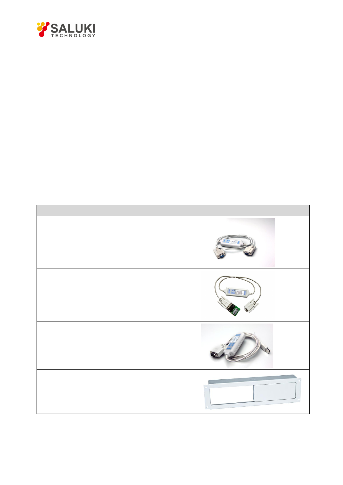
5.1 M131/M132/M133 Communication Cable........................................................................................ 28
5.2 Communication between Power Supply and PC................................................................................ 29
Chapter 6 SCPI Communication Protocal............................................................................................ 31
6.1 SCPI Communication Command Introduction...................................................................................31
6.2 Command Introduction of SPS8 Power Supply................................................................................. 32
6.2.1 Basic command (IEEE-488.2 Common Command Set)..............................................................32
6.2.2 System Command........................................................................................................................ 32
6.2.3 Measurement Command ............................................................................................................. 33
6.2.4 Setting Command ........................................................................................................................34
6.2.5 List Operation Related Command............................................................................................... 37

www.salukitec.com
5
Chapter 1 Introduction
SPS8 series power supply is high performance single-output programmable DC power supply with
communication interface, possessing the character of fast rise time speed (The rise speed of SPS811 power
supply can be less than 10mS and the SPS851 can be less than 20ms). The combination of bench-top and
system features in SPS8 power supplies provides versatile solutions for your design and test requirements. The
SPS8 series can not only be programmed through the keyboard on the panel, but also be functioned as
voltmeter and milliohmmeter, which will bring great convenience to the users. As a regeneration product of
ordinary programmable power supplies, SPS8 series power supply is more cost-effective.
SPS831 power supply, a new generation of programmable linear power supply, are designed with high speed
dynamic programming output (Voltage 0-30V, 1ms rising time), high current accuracy (0.001mA resolution)
and low internal resistance, which can satisfy all the test requirements. Meanwhile, the voltage level switch
works without relay, which will cause the fast switch between high voltage and low voltage. Moreover, SPS831
power supply provides the best solutions for cellphone research, micro-electronics lab, research institute and
special users requiring power supply with low current but high accuracy.
Features
Low ripple and noise
High resolution and accuracy (0.1mV/0.01mA, SPS831 reaches up to 0.001mA)
Built-in a high-accuracy 5 1/2 voltmeter and milliohmmeter
Supporting high-accuracy and dynamic programming output
High-luminance VFD screen and two lines & four ways display
Smart fan will be automatically initiated according to the temperature
Supporting remote voltage compensation and multidata storage
Supporting external trigger input and output
Power-on-self-test, software calibration and standard rack mountable
Supporting RS232/RS485/USB interface

www.salukitec.com
6
Chapter 2 Technical Specifications
2.1 Main Technical Specification
(1) SPS81X series power supply technical specification table
Model
SPS811
SPS812
SPS813
SPS831
Output Rating
Voltage
0-30V
0-75V
0-150V
0-30V
Current
0-5A
0-2A
0-1A
0-1A
Load Regulation
Voltage
<0.01%+0.5mV
<0.01%+0.5mV
<0.01%+0.5mV
<0.01%+0.5mV
Current
<0.01%+0.1mA
<0.01%+0.1mA
<0.01%+0.1mA
<0.01%+0.1mA
Setting Value
Resolution
Voltage
0.5mV
1mV
2mV
0.5mV
Current
0.1mA
0.05mA
0.01mA
0.01mA
Readback Value
Resolution
Voltage
0.1mV
0.1mV
1mV
0.1mV
Current
0.01mA
0.01mA
0.01mA
0.001mA
Setting Value
Accuracy
Voltage
0.01%+2mV
0.01%+5mV
0.01%+10mV
0.01%+2mV
Current
0.05%+1mA
0.05%+0.5mA
0.05%+0.1mA
0.05%+0.1mA
Readback Value
Accuracy
Voltage
0.02%+5mV
0.02%+15mV
0.02%+35mV
0.02%+5mV
Current
0.1%+5mA
0.05%+2mA
0.05%+1mA
0.02%+1mA
Ripple
Voltage
3mvp-p
5mvp-p
10mvp-p
10mvp-p
Current
2mA rms
1mA rms
0.5mA rms
0.5mA rms
Voltmeter
Accuracy
0-12V Accuracy: 0.02%+2mV
0-58V Accuracy: 0.02%+5mV
Milliohmmeter
Accuracy
10W. 0-1000mΩ Accuracy: 0.2%+3mΩ
1000-10000 mΩ Accuracy: 0.2%+6mΩ
Working
Condition
0-40°C, 0-90%RH
Power Required
AC 120V/220V±10%, 50/60Hz
Weight
6.5Kg
Dimension
214mmW ×101.5mmH ×365mmD
(2) SPS85X series power supply technical specification table
Model
SPS851
SPS852
SPS853
Output Rating
Voltage
0-6V
0-30V
0-75V
Current
0-60A
0-20A
0-8A
Load Regulation
Voltage
<0.01%+1mV
<0.01%+1mV
<0.01%+1mV
Current
<0.01%+0.1mA
<0.01%+0.1mA
<0.01%+0.1mA

www.salukitec.com
7
Setting Value
Resolution
Voltage
0.1mV
0.5mV
1mV
Current
1mA
0.5mA
0.2mA
Readback Value
Resolution
Voltage
0.1mV
0.1mV
0.1mV
Current
0.1mA
0.1mA
0.1mA
Setting Value
Accuracy
Voltage
0.01%+1mV
0.01%+5mV
0.01%+10mV
Current
0.05%+6mA
0.05%+2mA
0.05%+1mA
Readback Value
Accuracy
Voltage
0.02%+2mV
0.02%+5mV
0.02%+15mV
Current
0.05%+45mA
0.05%+20mA
0.05%+8mA
Ripple
Voltage
3mvp-p
5mvp-p
7mvp-p
Current
15mA rms
7mA rms
4mA rms
Voltmeter Accuracy
0-12V Accuracy: 0.02%+2mV
0-58V Accuracy: 0.02%+5mV
Milliohmmeter
Accuracy
10W. 0-1000mΩ Accuracy: 0.2%+3mΩ
1000-10000 mΩ Accuracy: 0.2%+6mΩ
Working Condition
0-40°C, 0-90%RH
Power Required
AC 120V/220V+10%, 50/60Hz
Weight
28Kg
Dimension
428mmW ×88mmH ×453.5mmD
(3) SPS87X series power supply technical specification table
Model
SPS871
SPS872
SPS873
SPS874
Output Rating
Voltage
0-15V
0-30V
0-75V
0-100V
Current
0-60A
0-35A
0-15A
0-11A
Load Regulation
Voltage
<0.01%+1mV
<0.01%+1mV
<0.01%+1mV
<0.01%+1mV
Current
<0.01%+0.1mA
<0.01%+0.1mA
<0.01%+0.1mA
<0.01%+0.1mA
Setting Value
Resolution
Voltage
0.1mV
0.5mV
2mV
2mV
Current
1mA
0.5mA
0.2mA
0.2mA
Readback Value
Resolution
Voltage
0.1mV
0.1mV
0.1mV
1mV
Current
0.1mA
0.1mA
0.1mA
0.1mA
Setting Value
Accuracy
Voltage
0.01%+1mV
0.01%+5mV
0.01%+10mV
0.01%+15mV
Current
0.05%+6mA
0.05%+2mA
0.05%+1mA
0.05%+1mA
Readback Value
Accuracy
Voltage
0.03%+3mV
0.03%+5mV
0.03%+15mV
0.03%+25mV
Current
0.05%+45mA
0.05%+25mA
0.05%+12mA
0.05%+10mA
Ripple
Voltage
4mvp-p
5mvp-p
6mvp-p
8mvp-p

www.salukitec.com
8
Current
15mA rms
8mA rms
3mA rms
2.5mA rms
Voltmeter Accuracy
0-12V Accuracy: 0.02%+2mV
0-58V Accuracy: 0.02%+5mV
Milliohmmeter
Accuracy
10W. 0-1000mΩ Accuracy: 0.2%+3mΩ
1000-10000 mΩ Accuracy: 0.2%+6mΩ
Working Condition
0-40°C, 0-90%RH
Power Required
AC 125V/220V+10%, 50/60Hz
Weight
45Kg
Dimension
482mmW ×184.5mmH ×531mmD
2.2 Supplemental Characteristics
State storage memory: 50 user-configurable stored states
Recommended calibration interval: 1 year
AC input ratings (selectable via switch on the rear panel)
Option Opt.01: 220VAC ± 10%, 47 to 63 Hz
Option Opt.02: 110VAC ± 10%, 47 to 63 Hz
Cooling: forced cooling
Operating temperature: 0 to 40 °C
Storage temperature: -20 to 70 °C
Environmental conditions: designed for indoor use installation categoryⅡ, pollution degree 2
environment. Designed to operate at maximum relative humidity of 90%
2.3 SPS8 Power Supply Dimension
The dimension of SPS81X/SPS831 series is 214mm W ×101.5mm H ×365mm D.

www.salukitec.com
12
Chapter 3 Quick Start
This chapter mainly focuses on the brief introduction of the surface appearance and basic functions of SPS8
series power supply so that both experienced and inexperienced users can be acquainted with the new products
quickly. Meanwhile, the chapter also clarifies some preliminary checkout that should be made prior to
operation to make sure the normal running of the products.
3.1 Front Panel and Rear Panel
The front panel layout of SPS81X series power supply is as follows:
Diagram 3.1 Front Panel of SPS81X Series Power Supply
The upper half is black VFD display screen and knob
The bottom half, left side to right side, is numberic keys 0-9, esc key, function keys, up-down keys,
enter key, input terminall and output terminal
The rear panel layout of SPS81X is as follows:
Diagram 3.2 Rear Panel of SPS81X Series Power Supply
①cooling window
②multifunction connector (remote sensing connector, trigger connector and GND connector)

www.salukitec.com
13
③9-pin serial port interface connector
④line voltage selection switch (110 VAC or 220 VAC)
⑤AC input connector
3.2 Preliminary Checkout
The following steps help you verify that the power supply is ready for use.
1. Check the list of supplied items
Verify that you have received the following items with your power supply. If anything is missing, contact your
nearest sales office.
One power cord for your location
One CD (only when you have bought communication accessories)
One communication cable (only when you have bought communication accessories)
One test line (only SPS811 ,SPS812 ,SPS813, SPS831 have the test line)
2.Connect the power cord and turn on the power supply
When you turn on the power supply, the VFD display screen will light up briefly and the power supply
performs its power-on self-test. Please check if there is any stroke loss on VFD display.
Warning:Your power supply is equipped with a 3-wire grounding type power cord. The power
supply is grounded only when the power-line cord is plugged into an appropriate receptacle. Do not
operate your power supply without adequate cabinet ground connection.
3.3 If the Power Supply Does Not Turn On
Use the following steps to help solve problems you might encounter when turning on the instrument.
1.Verify that there is AC power to the power supply.
First, verify that the power cord is firmly plugged into the power receptacle on the rear panel of the power
supply. You should also make sure that the power source you plugged the power supply into is energized. Then,
verify that the power supply is turned on.
2. Verify the power-line voltage setting.
The line voltage is set to the proper value for your country (110VAC or 220VAC) when the power supply is
shipped from the factory. Change the voltage setting if it’s not correct.
3. Verify that the correct power-line fuse is installed.
If the fuse was damaged, please see the table below to replace the fuse for your power supply.

www.salukitec.com
14
Model
Fuse Description (110VAC)
Fuse Description (220VAC)
SPS811
T5A 250V
T3.15A 250V
SPS812
T5A 250V
T3.15A 250V
SPS813
T5A 250V
T3.15A 250V
SPS831
T5A 250V
T3.15A 250V
SPS851
T10A 250V
T6.3A 250V
SPS852
T10A 250V
T6.3A 250V
SPS853
T10A 250V
T6.3A 250V
SPS871
T15A 250V
T10A 250V
SPS872
T15A 250V
T10A 250V
SPS873
T15A 250V
T10A 250V
SPS874
T15A 250V
T10A 250V
4. How to replace the power-line fuse
Open the plastic cover which locates at below the power input socket in the rear panel of the power supply by
screwdriver, then you will see the fuse. Please replace the damaged fuse with the matched fuse.
3.4 How to Adjust the Carrying Handle
To adjust the position, grasp the handle by the sides and pull outward. Then, rotate the handle to the desired
position. There are following three positions for you to choose:
Diagram 3.3 SPS8 series Power Supply Viewing Positions
3.5 How to Rackmount the Instrument
The power supply can be mounted in a standard 19-inch rack cabinet and be easily applied to your testing
system. If you want to rackmount the SPS8 series, please buy M151 rack kit.

www.salukitec.com
16
Chapter 4 Panel Operation
This chapter mainly introduces the front-panel operation in detail from the following parts:
Key Layout
The Front Panel Operation Overview
Voltage Set Operation
Current Set Operation
Saving and Recalling Operation
Menu Operation
Output ON/OFF Operation
Remote Measurement Function
Milliohmmeter Function
Voltmeter Function
4.1 Key Layout
Diagram 4.1 Operation Panel
Multifunction Keys Description
0-9
Numberic keys
Menu
Menu operation key
List
List output operation
Trigger
Trigger key
V/mΩ
Voltmeter and milliohmmeter switch button
0.1W
Choose 0.1W power output operation when the instrument is used as an milliohmmeter
1W
Choose 1W power output when the instrument is used as an milliohmmeter
10W
Choose 10W power output when the instrument is used as an milliohmmeter
Local
Local operation
Multifunction Keys
Function Keys

www.salukitec.com
17
Esc
Esc key (can be exited from any working condition)
Function Keys Description
Set the voltage value
Set the current value
Save the current settings to a specified storage location
Recall the saved settings from a specified storage location
Menu operation: set the parameter of the power supply
Control the output on/off state
Used together with the multifunction keys to perform diversity functions and applications(for
example: shift+Menu can perform menu function)
▲
Up-key: choose menu item in menu operation or to increase the output voltage
▼
Down-key: choose menu item in menu operation or to reduce the output voltage
Enter the selected value or setting
4.2 Front-panel Operation Overview
The following section describes an overview of the front-panel keys before operating your power supply.
The power supply is shipped from the factory configured in the front-panel operation mode. At power-on,
the power supply is automatically set to operate in the front-panel operation mode. When in this mode, the
front panel keys can be used.
When the power supply is in remote operation mode, you cannot use the front-panel. A change between
front-panel and remote operation modes will not result in any change in the output parameters. You can
change the front-panel and remote operation modes by PC.
The output of the power supply can be enabled or disabled from the front panel by pressing the key
.
The VFD display shows the current operating status of the power supply with annunciators. When it is
powered on, the VFD will display two lines of data. The first line shows the actual voltage value, actual
current value and power supply’s status while the second line shows the voltage value that can be
measured by voltmeter and output setting value of the power supply.
4.3 Constant Voltage Operation
The constant voltage range is from 0V to the maximum voltage value of each model. It is very easy for you to
set the constant voltage output. You have 2 solutions to set the constant voltage value.
Solution 1:
Press the ▲ and ▼ keys to change the value when the SPS8 series power supply is powered on.
Solution 2:
Step1. Power on the SPS8 series instrument
V-set
I-set
Save
Recall
Menu
Enter

www.salukitec.com
18
Step2. Press key
Step3. Press the numeric keys to to enter the voltage value you wanted
Step4. Press to confirm the value
When you close Knob Lock function in Config menu, the following two operations also can be used:
1) Use upper revolving encoder directly to adjust voltage;
2) Press key then use upper revolving encoder to adjust voltage
4.4 Constant Current Operation
The constant current output range is from 0 A to the maximum current value of each type. It is very easy for
you to set the constant current output.
Step1. Power on the SPS8 series instrument
Step2. Press key
Step3. Use the numeric keys to to enter the voltage value you wanted
Step4. Press key to confirm the value
If you close knob lock function in config menu, please use following operation:
Press key then use upper revolving encoder to adjust voltage
4.5 Saving and Recalling Operation
You can store up to 50 different output states in storage register locations(0~49) so that you can recall the saved
settings quickly. This kind of store operation can be performed by the keys and located in
the front panel. When the fast recalling is activated, you can press the numberic keys to to invoke
the corresponding data.
Each output state includes: 1. Constant voltage value, 2. Constant current value, 3. Maximun voltage setting
value, 4. Step voltage value.
After you setting an output state (CV value, CC value and Maximum voltage), press the key
and the numeric keys to to store the output value in a specified memory location.
Press the key and the numeric keys to to recall the output value from a specified memory
location.
4.6 Menu Operation
4.6.1 Menu Description
Press the key to access to the menu function and at the moment the VFD display screen shows the
menu items. You can select the menu items by pressing the ▲ and ▼ keys or by rotating the knob, and then
press the key to enter in the menu item you wanted. Or you can press the key to get back to
the higher level menu.
The first level menu includes:
V-Set
Enter
0
Enter
I-Set
0
Save
Recall
0
0
V-Set
I-Set
0

www.salukitec.com
19
Config: set the function of power supply
System set: set the system parameter
List Set: set list operation
Auto test: set auto test operation
Output Timer: set the duation of output
SN: the serial number of the power supply
Exit: exit the first-level menu
When accessing to Config item, the following menu items will be displayed on the VFD display screen by
pressing the keys ▲ and ▼.
Init: set all settings to factory default set
Out Memory: set the power supply’s output state when it is powered on
TRI KeepOut: set TRI as preseved output port
Fast Recall: set key shortcut function
Key Sound: set the key sound
Knob Lock: set the knob lock state
On
Setting the same state as last time you turned off the
power supply.
Off(Default)
Setting the output to OFF state when the power
supply is powered on.
On
When TRI is in low voltage level, the output state of
power supply is ON.
When TRI is in high voltage level, the output state
of power supply is OFF.
When the TRI KeepOut is enabled, the ON/OFF on
the front panel is invalid.
The TRI Keepout is only valid to ordinary operation
mode. It is invaid to list opeartion and auto test
mode.
Off(Default)
Disabled
On
In the main interface (not enter any menu of the
power supply), press the key 0~9 to recall
the parameters set by Save function
Off(Default)
Disabled
On(Default)
The buzzer will sound when any key was pressed.
Off
The buzzer will not sound when any key was
pressed
On
The knob is locked and rotating the knob will not
cause any change of the setting value.
Off(Default)
The knob is unlocked and rotating the knob will
cause change of the setting value.

www.salukitec.com
20
Remote Sense: set the remote sense mode
Curr Unit: set the unit of current
Match Power: set the matching power
50 HZ(Default)
Match 50HZ
60 HZ
Match 60HZ
Baudrate Set: set the baud rate
4800
Setting the baudrate as 4800bps
9600(Default)
Setting the baudrate as 9600bps
19200
Setting the baudrate as 19200bps
38400
Setting the baudrate as 38400bps
Comm. Parity: set the communication parity
None(Default)
Setting no parity bit
Even
Setting comm. parity as even parity bit
Odd
Setting comm. parity as odd parity bit
Key Lock Set: set the key lock and password function
Password=
When set the password as 0 or pressing the key
Enter directly, the Key Lock Set is disable.
When the Key Lock Set is enable, the Key Lock
Set get locked if no keyboard operation within 60
seconds, the Key Lock Set gets enable only if
you input the correct password.
Exit: exit from the current menu
When accessing to System Set item,the following menu items will be displayed on the VFD display screen by
pressing the keys ▲ and ▼.
Max Volt: set the maximum voltage of the power supply
Max Volt=
Setting the maximum voltage
Step Volt: set the step voltage
Step=
After the step voltage set, the voltage value
increases or discreases equal to each step voltage
by pressing the key ▲ or ▼ once.
On
Activating the remote sense mode ( Rear-panel
measurement mode)
Off(Default)
Activating the front-panel measurement mode
mA
Set the unit of current is mA
A(Default)
Set the unit of current is A
This manual suits for next models
14
Table of contents
Popular Power Supply manuals by other brands

Altronix
Altronix AL176UL installation instructions

Techly
Techly IPW-12DC15A manual

Unitek
Unitek UNIBOND II Operation, maintenance and service manual

Calira
Calira EVS 36/20-DS/IU Operating and installation instructions

Puls
Puls FPH500.245-047-104 manual

Huawei
Huawei Telecom Power TP48200A-HT19C3 user manual