Samlex Europe BBM1224i User manual

www.samlex.com
www.samlex-solar.com
BBM1224i
Model No.
BATTERY BACKUP MODULE
Please read thismanual before installing your backup module
BATTERY BACKUP MODULE 12/24
Gebruiksaanwijzing/Owners Manual
Gebrauchsanweisung/Mode d’emploi

Read the owners manual carefully before installing the BBM1224i!
Features
Automatic 12 V / 14 V detection Simple installation
Purpose
The BBM1224i has to functions:
1. To ensure that the connected devices is always supplied with sufficient current and voltage.
2. To ensure that the battery is not discharged too much.
Wiring diagram
Installation
1. Connect the plus (+) of the load to the OUT+ of the BBM1224i.
2. Connect the minus (-) of the load to a minus (-) of the BBM1224i.
3. Connect the plus (+) of the battery to the BAT+ of the BBM1224i.
4. Connect the minus (-) of the battery to a minus (-) of the BBM1224i.
5. Connect the plus (+) of the power supply to the PS+ of the BBM1224i.
6. Connect the minus (-) of the power supply to a minus (-) of the BBM1224i.
Warnings:
The product should only be connected by skilled fitters/mechanics who are aware of the regulations for working with high battery voltages.
The use of poor quality connection materials and/or excessively thin cables may result in damage to the product.
A short circuit between the positive and negative terminals of the battery may cause severe damage to your system.
Do not locate the product close to combustible and highly flammable materials.
Always use fuses.
Operation
New from the box the relay will connect the battery to the load. Once the BBM1224i is connected to the power supply, the relay will switch on whereby the
power is connected to the load and the battery. The moment the power supply no longer delivers energy to the product – because it is, for example,
disconnected or broken – the load will immediately receive its power from the battery. In order to make an as efficient as possible system, after 100 ms the
relay will switch over so that current no longer passes through the internal diodes but via the relay to the load.
If the power supply is then connected to the product once more, the relay will again switch on after 3 seconds in order to supply the load with power from the
power supply and to also charge the battery again.
Charging current setting
If the blade fuse – which is visible on the rear of the housing – is removed, the maximum charging current for a 12 V system is 2 A and for a 24 V system is 4
A.
Note!
It is important that the connected power supply can deliver at least as much power as the connected load requires. If a weaker power supply is connected, the
relay will constantly switch on and off.
Technical details
12V system 24V system
Input voltage 13.8 V 27.6 V
Maximum input current (PS) 35 A
Current to load (Out) to 31 A to 27 A
Current to battery (Bat) to 4 A to 8 A
Current consumption (without load) 140 mA @ 13.8V
74 mA @ 27.6 V
Voltage loss from power supply (PS) or battery (Bat) to load (Out) ±50 mV @ 20 A
No power failure when switching from the power supply (PS) to the battery (Bat), and vice versa.
Owners Manual BBM1224i EN_DU_FR_NL 140710

Lesen S ie die Gebrauchsanweisung zuerst aufmerksam durch, bevor Sie den BBM1224i anschließen!
Eigenschaften
Automatische 12V / 24V Detektion Einfache Installation
Zweck
Der BBM1224i hat zwei Funktionen:
1. 1. Dafür sorgen, dass die angeschlossenen Geräte immer mit ausreichend Strom und ausreichender Spannung versehen werden.
2. 2. Dafür sorgen, dass die Batterie nicht zu weit entladen wird.
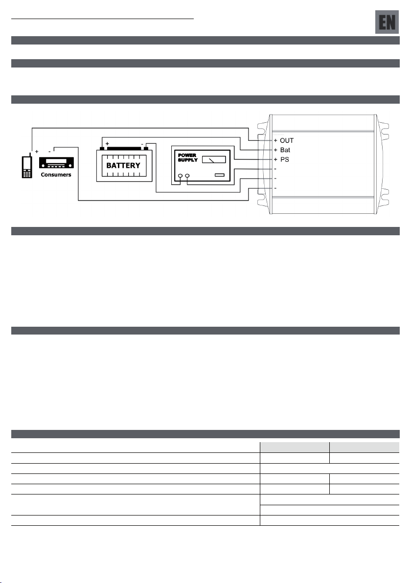
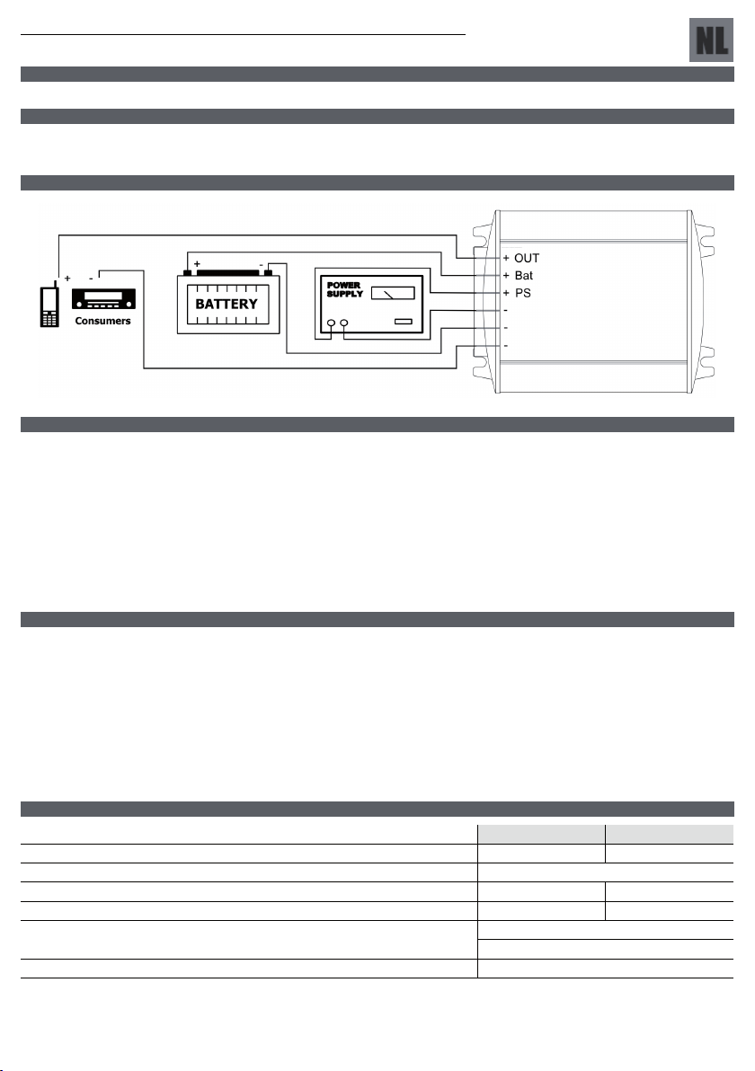
Schaltplan
Installation
1. Den Pluspol (+) des Stromabnehmers an OUT+ des BBM1224i anschließen.
2. Den Minuspol (–) des Stromabnehmers an den Minuspol (-) des BBM1224i anschließen.
3. Den Pluspol (+) der Batterie an BAT+ des BBM1224i anschließen.
4. Den Minuspol (-) der Batterie an einen Minuspol (-) des BBM1224i anschließen.
5. Den Pluspol (+) der Speisung an den PS+ des BBM1224i anschließen.
6. Den Minuspol (-) der Speisung an einen Minuspol (-) des BBM1224i anschließen.
Warnhinweise:
Das Produkt darf nur von fachkundigen Installateuren / Monteuren angeschlossen werden, die die Vorschriften für das Arbeiten mit hohen
Batteriespannungen kennen.
Bei Gebrauch von schlechtem Anschlussmaterial und / oder zu dünnen Drähten kann das Produkt beschädigt werden.
Kurzschluss zwischen dem Plus- und Minusanschluss der Batterie kann Ihr System schwer beschädigen.
Stellen Sie das Produkt nicht zu nahe an brennbare und leicht entflammbare Materialien
Gebrauchen Sie immer Sicherungen.
Funktion
Direkt nach dem Auspacken wird das Relais die Batterie mit dem Stromabnehmer verbinden. Sobald der BBM1224i an die Speisung angeschlossen wird, wird
sich das Relais einschalten, wodurch die Speisung mit dem Stromabnehmer und der Batterie verbunden wird. In dem Moment wenn die Speisung dem Produkt
keine Energie mehr liefert – beispielsweise weil es abgekoppelt oder defekt ist – wird der Stromabnehmer unverzüglich aus der Batterie gespeist werden. Um
das System so sparsam wie möglich zu machen, wird nach 100ms das Relais umschalten, sodass Strom nicht mehr durch die internen Dioden läuft, sondern
über das Relais zum Stromabnehmer geht.
Wenn danach die Speisung wieder an das Produkt angeschlossen wird, wird sich das Relais nach 3 Sekunden wieder einschalten, um den Stromabnehmer
wieder aus der Speisung zu speisen und auch die Batterie wieder aufzuladen.
Einstellung Ladestrom
Falls die Stecksicherung – die an der Rückseite des Gehäuses sichtbar ist – entfernt wird, wird der maximale Ladestrom für ein 12V System 2A sein und für ein
24V System 4A.
Achtung!
Es ist wichtig, dass die angeschlossene Speisung genauso viel Strom liefern kann, wie der angeschlossene Stromabnehmer benötigt. Falls eine schwächere
Speisung angeschlossen wird, wird sich das Relais immer ein- und ausschalten.
Technische Daten
12V System 24V System
Eingangsspannung 13,8V 27,6V
Maximaler Eingangsstrom (PS) 35A
Strom zum Stromabnehmer (Out) bis 31A bis 27A
Strom zur Batterie (Bat) bis 4A bis 8A
Stromaufnahme (ohne Stromabnehmer) 140mA @ 13,8V
74mA @ 27,6V
Spannungsverlust der Speisung (PS) oder Batterie zum Stromabnehmer (Out) ±50mV @ 20A
Kein Spannungsausfall beim Umschalten von der Speisung (PS) zur Batterie (Bat) und umgekehrt.
Owners Manual BBM1224i EN_DU_FR_NL 140710

Veuillez lire attentivement le mode d'emploi avant de brancher le BBM1224i!
Propriétés
Auto détection 12 V / 24 V Installation facile
Objectif
Le BBM1224i a deux fonctions::
1. Faire en sorte que l'appareillage branché soit toujours pourvu de façon suffisante en électricité et en tension.
2. Faire en sorte que la batterie ne se décharge pas de façon trop importante.
Schéma des connexions
Installation
1. Raccorder le plus (+) de la charge sur OUT+ du BBM1224i.
2. Raccorder le moins (–) de la charge sur un moins (-) du BBM1224i.
3. Raccorder le plus (+) de la batterie sur BAT+ du BBM1224i.
4. Raccorder le moins (-) de la batterie sur un moins (-) du BBM1224i.
5. Raccorder le plus (+) de l'alimentation sur PS+ du BBM1224i.
6. Raccorder le moins (-) de l'alimentation sur un moins (-) du BBM1224i.
Avertissements:
Le produit ne doit être mis en place que par des installateurs / monteurs qualifiés, informés des prescriptions relatives au travail avec des dispositifs
de haute tension.
L'utilisation de matériaux de connexion de mauvaise qualité et/ou de câbles trop fins peut endommager le produit.
Un court-circuit entre le raccord négatif et le raccord positif de la batterie peut gravement endommager votre système.
Ne pas placer le produit à proximité de matériaux combustibles et facilement inflammables.
Toujours utiliser des fusibles.
Fonctionnement
Sorti de sa boîte, le relais reliera la batterie à la charge. Dès que le BBM1124i est branché sur l'alimentation, le relais établira le circuit, ce qui reliera
l'alimentation à la charge et à la batterie. Dès que l'alimentation ne fournit plus d'énergie au produit – par exemple parce qu'il est débranché ou en panne – la
charge est immédiatement alimentée par la batterie. Afin de créer un système aussi économe que possible, le relais s'inverse après 100 ms afin que le courant
ne passe plus par les diodes internes mais alimente la charge par la voie du relais.
Si ensuite l'alimentation est de nouveau raccordée au produit, le relais rétablira le circuit après 3 s afin de nouveau d'alimenter la charge par l'alimentation et de
recharger également la batterie.
Réglage du courant de charge
Si le fusible à broche – qui est visible à l'arrière du boîtier – est retiré, le courant de charge maximum sera de 2 A pour un système de 12 V et de 4 A pour un
système de 24 V.
Attention!
Il est important que l'alimentation branchée puisse fournir au moins autant de courant que nécessaire à la charge. Si une alimentation plus faible est branchée,
le relais ne cessera d'établir et de couper le circuit.
Spécifications techniques
Système 12 V Système 24 V
Tension d'entrée 13,8 V 27,6 V
Courant d'entrée maximum (PS) 35 A
Courant vers la charge (Out) jusque 31 A jusque 27 A
Courant vers la batterie (Bat) jusque 4 A jusque 8 A
Courant absorbé (sans charge) 140 mA @ 13,8 V
74 mA @ 27,6 V
Perte de tension de l'alimentation (PS) ou de la batterie (Bat) vers la charge (Out) ±50 mV @ 20 A
Pas de chute de tension lors de la commutation de l'alimentation (PS) vers la batterie (Bat) et vice-versa.
Owners Manual BBM1224i EN_DU_FR_NL 140710

Lees de gebruiksaanwijzing eerst aandachtig door alvorens de BBM1224i aan te sluiten!
Eigenschappen
Automatische 12V / 24V detectie Eenvoudige installatie
Doel
De BBM1224i heeft twee functies:
1. Er voor zorgen dat de aangesloten apparatuur altijd is voorzien van voldoende stroom en spanning.
2. Er voor zorgen dat de batterij niet te ver ontladen wordt.
Aansluitschema
Installatie
1. De plus (+) van de belasting aansluiten op de OUT+ van de BBM1224i.
2. De min (–) van de belasting aansluiten op een min (-) van de BBM1224i.
3. De plus (+) van de batterij aansluiten op de BAT+ van de BBM1224i.
4. De min (-) van de batterij aansluiten op een min (-) van de BBM1224i.
5. De plus (+) van de voeding aansluiten op de PS+ van de BBM1224i.
6. De min (-) van de voeding aansluiten op een min (-) van de BBM1224i.
Waarschuwingen:
Het product mag alleen door vakbekwame installateurs / monteurs die op de hoogte zijn van de voorschriften voor het werken met hoge accu
spanningen worden aangesloten.
Bij gebruik van slecht aansluitmateriaal en / of te dunne draden kan het product beschadigen.
Kortsluiting tussen de plus en min aansluiting van de accu kan uw systeem zwaar beschadigen.
Plaats het product niet dicht bij brandbare en licht ontvlambare materialen.
Gebruik altijd zekeringen.
Werking
Nieuw uit de doos zal het relais de batterij doorverbinden met de belasting. Zodra de BBM1224i aangesloten wordt op de voeding, zal het relais inschakelen
waardoor de voeding verbonden wordt met de belasting en de batterij. Op het moment dat de voeding geen energie meer levert aan het product – omdat hij
bijvoorbeeld losgekoppeld of stuk is – zal de belasting onmiddellijk uit de batterij gevoed worden. Om een zo zuinig mogelijk systeem te maken zal na 100ms
het relais omschakelen zodat stroom niet meer door de interne diodes loopt maar via het relais naar de belasting gaat.
Als vervolgens de voeding weer wordt aangesloten op het product, zal het relais na 3 sec. weer inschakelen om de belasting weer te voeden uit de voeding en
ook de batterij weer op te laden.
Laadstroom instelling
Indien de steekzekering – die zichtbaar is aan de achterkant van de behuizing – verwijdert wordt, zal de maximale laadstroom voor een 12V systeem 2A zijn en
voor een 24V systeem 4A.
Let op!
Het is belangrijk dat de aangesloten voeding minstens net zoveel stroom kan leveren als de aangesloten belasting nodig heeft. Indien een zwakkere voeding
aangesloten wordt, zal het relais steeds in- en uitschakelen.
Technische gegevens
12V systeem 24V systeem
Ingangsspanning 13,8V 2 7,6V
Maximale ingangsstroom (PS) 35A
Stroom naar belasting (Out) tot 31A tot 27A
Stroom naar batterij (Bat) tot 4A tot 8A
Opgenomen stroom (zonder belasting) 140mA @ 13,8V
74mA @ 27,6V
Spanningsverlies van voeding (PS) of batterij (Bat) naar belasting (Out) ±50mV @ 20A
Geen spanningsuitval bij omschakeling van de voeding (PS) naar de batterij (Bat), en omgekeerd.
Owners Manual BBM1224i EN_DU_FR_NL 140710

www.samlex.com
www.samlex-solar.com
BBM1224i
Model No.
BATTERY BACKUP MODULE
Please read thismanual before installing your backup module
BATTERY BACKUP MODULE 12/24
Gebruiksaanwijzing/Owners Manual
Gebrauchsanweisung/Mode d’emploi
Table of contents
Languages:
Popular Control Unit manuals by other brands

Enclustra
Enclustra Mercury+ XU8 user manual

Neoway
Neoway N75-NA user manual

Enerpac
Enerpac VM43-LPS instruction sheet

ALT
ALT AquaBrass ThermOne 61264 installation guide

Telit Wireless Solutions
Telit Wireless Solutions ME50-868 user guide

Steady State Fate
Steady State Fate Mixmode Control and function reference guide