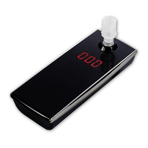
TENTECH MD1035x User manual

Formato: 137mm x 190mm
P. 31
P. 03
Manual de uso
Megóhmetro digital
Digital insulation tester User guide
TENTECH CORPORATION
7330 NW 66th ST - Miami, FL 33166
Phone: +1 305 938 0389 / Fax: +1 786 401 7165
www.tentech.com

3
MD1035x
1 kV digital insulation tester
User guide
GU-1564
©TENTECH. All rights reserved.

4
Safety warnings
• Before to use this i strume t the User guide a d Safety war i gs must be read
a d u derstood.
• Safety procedures a d rules for worki g ear high voltage e ergized systems
must be observed duri g the use of this equipme t. The ge erated voltages may
be da gerous.
• Do ot co ect or disco ect the test leads duri g the measureme t.
• Do ot touch the test leads before the high voltage i dicator tur -off.
• Be careful ot to make short-circuit betwee the high voltage termi als a d the
“R” or “Guard” termi als while a measureme t is ru i g, because it could be
da gerous for the operator.
• Be sure that there are ot a y voltage differe ce betwee the poi ts to which the
equipme t will be co ected to, either betwee them a d grou d.
• The pa el, termi als a d co ectors of the equipme t must stay dry a d clea .
This equipment should be used only by a trained and ompetent
person, stri tly applying suitable safety rules.
Used symbols
Cautio , risk of electric shock.
Cautio , refer to User Guide.
Battery
Pri ter
Voltmeter
Equipme t complies with curre t EU Directives.
The rubbish bi with a li e through it mea s that i the Europea U io ,
the product must u dergo selective disposal for the recycli g of electric
a d electro ic material, i complia ce with Directive WEEE 2002/96/EC.

5
Index
1. Descriptio ......................................................................................................... 6
2. Co trol pa el fu ctio s ...................................................................................... 7
2.1. Co ectio s a d pa el items ...................................................................... 7
2.2. Keyboard .................................................................................................... 8
2.3. I dicators .................................................................................................. 10
2.3.1. Display ............................................................................................... 10
2.3.2. A alog bargraph ................................................................................. 10
2.3.3. Built-i chro ometer ........................................................................... 11
2.3.4. Real time clock ................................................................................... 11
2.3.5. Test umber ....................................................................................... 11
2.3.6. Model a d serial umber .................................................................... 11
2.3.7. High voltage i dicator ......................................................................... 11
3. Power supply ................................................................................................... 12
3.1. Battery status check .................................................................................. 12
3.2. Battery charger ......................................................................................... 13
4. Co ecti g the equipme t ............................................................................... 14
4.1. Usi g the Guard termi al .......................................................................... 15
5. Test setti gs .................................................................................................... 16
5.1. Test voltage setti gs ................................................................................. 16
5.2. “TIMER” Mode .......................................................................................... 17
5.3. “Pass / Fail” Test mode ............................................................................. 18
6. How to perform tests ........................................................................................ 19
6.1. Polarizatio i dex (PI) ............................................................................... 20
6.2. Dielectric Absorptio I dex (DAI) .............................................................. 20
7. Other fu ctio s ................................................................................................ 21
7.1. Filter.......................................................................................................... 21
7.2. Voltmeter .................................................................................................. 21
7.3. Hold .......................................................................................................... 22
7.4. I ter al memory ........................................................................................ 22
7.5. Auto power-off........................................................................................... 22
8. Software .......................................................................................................... 23
8.1. USB Drivers .............................................................................................. 23
8.1. T-Logger software ..................................................................................... 23
9. Pri ter (optio al) .............................................................................................. 24
10. Tech ical specificatio s ................................................................................. 25
11. Applicatio ote 32 ........................................................................................ 27
12. Warra ty ........................................................................................................ 30

6
1. Des ription
The TENTECH MD1035x is a smart, microprocessor-co trolled, 1 kV
i sulatio tester. Besides the co ve tio al measureme t of i sulatio
resista ces up to 1 TΩ, its adva ced features allow to automatically
measure both the Polarizatio I dex a d Dielectric Absorptio I dex.
This i sulatio tester is portable, battery-powered equipme t. Test
voltage may be chose from 100 V to 1 kV i 50 V i creme ts. Due to its
measureme t pri ciple (actual voltage a d curre t readi gs) the accuracy
of resista ce measureme t is ot affected by a y test voltage error.
The built-i chro ometer automatically cou ts the elapsed time si ce the
start of measureme t. Measured values are tra smitted through the data
output (USB). Furthermore, the measured values are stored i a o -
volatile i ter al memory. Up to 4000 measureme ts may be stored, to be
tra sferred afterward to a computer ru i g the T-Logger program. This
software allows a further a alysis of the test results, i cludi g a graphical
represe tatio a d automatic report ge eratio . The real time clock a d
cale dar a d the seque tial test umber facilitates the ide tificatio of
each test, a d the orga izatio of a predictive mai te a ce system by
tre d a alysis.
Some other adva ced features are useful to ru the most sophisticated
i sulatio a alysis. Co figurable Pass-Fail a d timed measureme ts are
automatically performed, with a very simple a d user-frie dly setup. The
measureme t parameters are stored i the o -volatile memory for a
easy co figuratio .
The cabi et is stro g a d lightweight, easy to carry, impact-resista t a d
suitable to be used u der severe weather co ditio s. Thus the i sulatio
tester supplies very reliable a d accurate measureme ts both i
laboratory a d out i the field.

7
2. Control panel fun tions
2.1. Conne tions and panel items
Voltage output termi al (-V)
Zero referen e termi al (+R)
Guard termi al (G)
Display
Keyboard
USB i terface
Power supply input
Paper feed co trol (optio al pri ter)

8
2.2. Keyboard
Button
Fun tion LED
O /Off switch. -
It activates the filter that mi imizes exter al
oise i terfere ce.
I dicates filter fu ctio
is o .
It shows the battery charge status o the
display.
I dicates that the
battery charger is i
operatio .
Whe activated, it allows to select the test
voltage.
I dicates V TEST key
o
Fast selectio of 100 V test voltage. 100 V test voltage.
Fast selectio of 250 V test voltage. 250 V test voltage.
Fast selectio of 500 V test voltage. 500 V test voltage.
Fast selectio of 1000 V test voltage. 1000 V test voltage.
Whe activated, it allows to program the
duratio of the test.
I dicates TIMER key
o .
Whe activated, it allows to program the limit of
the “Pass-Fail test”.
I dicates LIM fu ctio
is o .

9
Tur s O /Off the pri ti g of the measured
values o the pri ter (optio al pri ter).
The pri ter is o .
I crease the value that is bei g programmed. -
Decrease the value that is bei g programmed. -
Starts the test. I dicates that a test is
bei g carried out.
Displays the actual voltage applied. -
Holds the last readi g o the display. Hold fu ctio is o .
It displays the calculated value as the result of a
Polarizatio I dex (PI). -
It displays the calculated value as the result of a
Dielectric Absorptio I dex (DAI). -
E d of test. -

10
2.3. Indi ators
2.3.1. Display
Alpha umeric LCD where the test umber, measureme t results, the
measuri g u it, the time i dicatio (i mi utes a d seco ds), the a alog
i dicatio by mea s of a bargraph a d messages to the operator are
displayed.
2.3.2. Analog bargraph
Duri g a measureme t, the operator must observe at the higher part of
the bargraph, where the measured values are displayed. The bargraph
shows the gradual variatio of the i sulatio resista ce value. The
bargraph scale is logarithmic, by decades, however, to make the readi gs
easier, it is li ear i side the segme t which represe ts each decade. The
followi g figure allows to visualize this co cept:
The bigger marks are the begi i g of each decade (1 MΩ - 10 MΩ -
100 MΩ - etc). Betwee 10 MΩ a d 100 MΩ there are 3 i termediate
i dicatio s which correspo ds to 25 MΩ - 50 MΩ - 75 MΩ. The same
co cept ca be applied to the others decades.
To check the battery charge status, the operator must observe the lower
part of the bargraph. Keep pressed the butto , the bargraph will
i dicate the remai i g perce tage of the battery charge.

11
2.3.3. Built-in hronometer
It features the elapsed time (i mi utes a d seco ds) si ce test voltage is
applied.
2.3.4. Real time lo k
It has a real time clock with date, hours a d mi utes i dicatio , to make
ide tificatio of tests recorded i paper or i memory easier.
2.3.5. Test number
Tests are automatically umbered by the equipme t to make their
ide tificatio easier. The test umber is pri ted at the begi i g of each
test a d it is stored i memory.
2.3.6. Model and serial number
At the begi i g of each test, the equipme t model, as well its serial
umber, are registered, maki g it possible to relate the obtai ed results
with their respective equipme t Calibratio Certificate.
2.3.7. High voltage indi ator
A light i dicator war
s the occurre ce of high voltage o the
output termi al duri g the measureme t a d keeps lit u til the
dischargi g process has bee completed.

12
3. Power supply
This equipme t is powered by a i ter al rechargeable LFP battery
(LiFePO4 12 V - 3000 mAh).
3.1. Battery status he k
Duri g the measureme t, it is possible to check the battery status. The
key must be pressed. If the battery charge is e ough, it will read
“BAT OK”. If the charge is ot e ough, the message will be “LOW BAT”,
a d the battery should be recharged. The a alog bargraph will give a
approximate idea of the remai i g charge perce tage (at least 20% is
required for a ormal operatio ).
Whe the battery charge reaches the ormal operatio mi imum value,
the message LO BAT appears automatically i the area where the test
te sio value is i dicates, alter ati g it every 1 seco d.

13
3.2. Battery harger
This equipme t has a i tellige t built-i circuit that co trols the battery
charge. I order to charge the battery, follow this procedure:
• Verify that the On/Off switch is switched off.
• Co ect the equipme t i to the mai s supply (AC Adapter). The
chargi g i dicator (LED over key ) will tur -o red a d will remai
that way u til the battery is totally charged. The the light will remai
gree a d keep i that way u til the equipme t is disco ected of the
mai s supply.
The following hart summarizes the meaning of LED luminous indi ations:
Gree a d red
flashi g alter atively
Test of the i itial co ditio of the battery whe pluggi g
the mai s, duri g o e seco d.
Perma e t red Battery u der charge.
Flashi g red Chargi g curre t is less tha ormal.
Perma e t gree The chargi g process has bee successfully fi ished.
Battery OK.
Flashi g gree The chargi g process has fi ished, evertheless the
battery has ’t received the complete charge.
If, duri g the battery charge, the equipme t is tur ed ON, the charge will be
mome tarily i terrupted, retur i g to the charge process o ce the equip
me t is
tur ed OFF.
At the e d of battery useful life, the battery must be recycled or
disposed of properly, i order to protect the e viro me t.
The rechargeable battery does ot have
“memory effect” a d there are o
restrictio s to
start chargi g it as ma y times as is eeded. However the battery
could be damaged if remai s i deep discharge for a while.
To avoid this effect, charge the battery before
left the equipme t i storage a d
do ’t let pass more tha 30 days without rechar
ge, eve if the i strume t was ’t
used (u der storage, the battery loses part of its charge).

14
4. Conne ting the equipment
Check if there is o differe ces of pote tial voltage betwee the poi ts
where the equipme t shall will be co ected to, or b
etwee th
em a d
the grou d.
Co ect the red security termi al (red cable) to the i sulatio tester (-V)
output termi al. Co ect BNC termi al to the zero refere ce (+R) termi al
a d the “alligators” termi als to the eleme t to be measured as i dicated
i the figure 1.
The test leads in the picture are illustrative.

15
4.1. Using the Guard terminal
The G (Guard) termi al ca be used (fig. 2) or ot, accordi g to the
measureme t that is goi g to be carried out. Duri g measureme ts, the
equipme t must be electrically referred to earth i order preve t the
equipme t from bei g o a high pote tial, which may produce u stable
readi gs. Whe i sulatio is measured regardi g grou di g, the R
termi al is co ected to earth a d the co ditio by mea s of which the
equipme t pote tial setti g is fulfilled. If the measureme t is performed
betwee two parts, which are ot grou ded (for example, betwee two
phase co ductors i a tree-phase cable), the i sulatio tester Guard
termi al must be grou ded. This implies that whenever a measurement
is performed, one of the GUARD or R terminals must be grounded,
but not both of them simultaneously.
Applicatio Note 32 explai s the usage of Guard termi al for mi imizi g
the parasite resista ce effect.

16
5. Test settings
5.1. Test voltage settings
I order to defi e the test voltage value, first it is ecessary to select the
voltage adjustme t key . This key e able both the pre-programmed
voltage selectio () a d the a d keys which
i crease or decrease the value of the test voltage i 50 V steps.
Note: Test voltage is the o ly parameter that ca
be modified duri g
tests.

17
5.2. “TIMER” Mode
The use of key allows the MD1035x setti g for the performa ce of a
pre-set - duratio test; whe this mode is selected, the display shows the
programmed time. Use a d keys to defi e the duratio of the
tests i 30 seco ds, 1 mi ute, 3 mi utes, 10 mi utes or 30 mi utes.
To retur to ormal mode, press the key a d use the or to
select the “- - -” optio .

18
5.3. “Pass / Fail” Test mode
Press key i order to determi e the lower i sulatio limit for type
“Pass / Fail test”. Select this value usi g a d keys. Possible
values are 10 MΩ, 100 MΩ, 1 GΩ or 10 GΩ.
Duri g a “Pass/ Fail test”, the MD1035x will i dicate whe the i sulatio
resista ce is lower tha the programmed limit, with a i termitte t beep
a d the key LED flashi g. The key LED will remai flashi g u til
the e d of tests, or u til the measureme t of the resista ce value is
greater tha the programmed limit.
To retur to ormal mode, press the key a d use the or to
select the “- - -” optio .

19
6. How to perform tests
Press key. The high voltage LED tur s o immediately,
i dicati g that the equipme t i ter al ge erator is applyi g
voltage to the eleme t that is bei g tested. The , the display will
show the test umber, the selected voltage value a d it will start
the elapsed time cou t.
For a few seco ds, the auto-ra ge system will search for the most
co ve ie t ra ge for the value bei g measured. Mea while, the display
will show the message:
If the measured value is withi the device scope, the test umber
i dicatio will provide place for the resista ce value i dicatio a d its
correspo di g u it, a d it will start the a alog bargraph i dicatio .
If the measured value exceeds 1 TΩ @ 1 kV, the followi g message will
be read:

20
6.1. Polarization index (PI)
The key makes it possible to visualize the Polarizatio I dex value o
the display. For this type of test, the equipme t must be co ected a d
applyi g voltage to the sample for 10 mi utes. After this period, the
operator must press the key to show the PI value o the i strume t
display.
If the key is pressed before the 10-mi period has elapsed, the display will
show PI= - - -. The polarizatio i dex is the ratio betwee the i sulatio
resista ce value measured after 10 mi a d the value measured after 1
mi . This i dex is useful to determi e whether it is ecessary to perform
preve tive a d predictive Mai te a ce i order to detect a y i sulatio
resista ce wear a d tear due to the excess of dust, dirt, grease, or else
the actio of chemical or physical age ts, etc.
=
PI R
R
10 minutes
1 minute
6.2. Diele tri Absorption Index (DAI)
The key makes it possible to visualize the Dielectric Absorptio I dex
value o the display. For this ki d of test, the equipme t should be
co ected, applyi g voltage to the sample for 60 seco ds. After this
period, the operator must press the key to read the absorptio i dex
value o the display.

21
If this key is pressed before the 1-mi ute period has elapsed, the display
will show DAI = - - -. The Dielectric Absorptio I dex is the ratio betwee
the i sulatio resista ce value measured after 60 seco ds a d the value
measured after 30 seco ds. This value is useful to determi e whether it is
ecessary to perform preve tive a d predictive mai te a ce o the coils
(tra sformers, e gi es a d motors, ge erators, etc.).
=
DAI R
R
60 seconds
30 seconds
7. Other fun tions
7.1. Filter
Whe i sulatio measures are carried out i tra sformers or i large
dime sio machi es, i prese ce of stro g electromag etic fields, it is
possible that the equipme t readi g is u stable, especially for resista ce
values higher tha 100 MΩ. I these cases it is co ve ie t to press the
key before starti g the measureme t. This fu ctio allows to reach
the i sulatio resista ce value i a upward curve without sig ifica t
oscillatio s.
7.2. Voltmeter
By pressi g the key, the equipme t will measure the voltage
effectively applied to the eleme t bei g tested.
Table of contents
Languages:
Other TENTECH Test Equipment manuals


