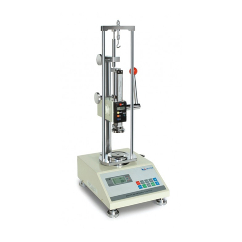
sauter SD Series User manual

SD-BA-e-2121
Sauter GmbH
Ziegelei 1
D-72336 Balingen
e-mail: info@kern-sohn.com
Phone : +49-[0]7433- 9933-0
Fax: +49-[0]7433-9933-149
Internet: www.sauter.eu
Instruction manual spring testing
system
SAUTER SD
Version 2.1
11/2021
GB
PROFESSIONAL MEASURING

2 SD-BA-e-2121
GB
SAUTER SD
V. 2.1 11/2021
Instruction manual spring testing system
Congratulations on your purchase of the SAUTER SD spring test bench. We hope you
enjoy your quality measurement system with its wide range of functions and high
reproducibility. If operated correctly, this high-quality product will give you many years
of use.
For questions, wishes or suggestions we are always at your disposal.
Table of contents:
Scope of delivery...................................................................................................... 3
1Weight and dimensions................................................................................. 3
2Check before use........................................................................................... 3
3Technical data................................................................................................ 3
4Operation........................................................................................................ 4
4.1 Display....................................................................................................................................... 4
4.2 Control keys.............................................................................................................................. 4
4.3 Limit value display good / bad................................................................................................ 6
4.4 Simple measurement (track mode)......................................................................................... 6
4.5 Peak hold function (peak mode)............................................................................................. 6
4.6 Auto Peak Hold Mode (Auto Peak Mode)............................................................................... 6
4.7 Minimum limit value function to activate the measured value storage.............................. 6
4.8 Storage of peak values and calculation of average values from up to 10 values ............. 7
4.9 Reset key................................................................................................................................... 7
5Thread of the fine adjustment screw............................................................ 7
6Printout to printer or PC................................................................................ 7
7General safety instructions........................................................................... 9

SD-BA-e-2121 3
Scope of delivery
-SAUTER SD
-Power cord
-Instruction manual
-Additional descriptions
1 Weight and dimensions
Test bench
SD 50N100
SD 100N100
SD 200N100
SD 500N100
Dimensions
(LxWxH)
300x235x620mm
Weight
21kg
2 Check before use
After receipt of the test stand, it should be checked in advance whether no transport
damage has occurred, whether the outer packaging, the metal housing, other parts
or even the test stand itself have been damaged. If any damage is evident, please
notify SAUTER GmbH immediately.
3 Technical data
Test bench
SD
50N100
SD
100N100
SD
200N100
SD
500N100
Maximum force
50 N
100 N
200 N
500N
Readability
0,01N
0,02N
0,05N
0,1N
Maximum stroke
length
100mm
Maximum
measuring room
height
100mm
Working
temperature
20±10°C
Storage and
transport temp.
-5°C~40°C
Relative air
humidity
15%~80%

4 SD-BA-e-2121
4 Operation
4.1 Display
(1) Measurement result
(2) Display unit of the measurement result
(3) PEAK indicates that peak hold mode is activated AUTO PEAK keeps the peak
value in the display only for a defined time (see 2.4)
(4) Display of the direction of force
(5) Assignment of the memory locations
(6) Average value or individual peak value
4.2 Control keys
ON / OFF:
On / Off button
(press the key for approx. 1 second)
UNIT: Measuring units
- Press the key briefly: Selection between N, kg and lb
ZERO: Zero position
Assignment with three functions:
- Zero setting of the display (tare function)
- Zeroing of the peak value (Peak)
- Saving a setting (in SET mode)
1
2
3
4
5
6

SD-BA-e-2121 5
SET:
Press once: Upper limit [HidT]. Press to change it: ▲ or ▼ (see 2.3)
Press once: Lower limit value [LodT]. Press to change it: ▲ or ▼(see 2.3)
Press once: Lower limit value to activate the memory function at
Peak value measurements (peak). [LE.SET / Lo Pe]. See also section 2.7.
Minimum limit function To change: ▲ or ▼ (Only in "Peak Mode")
activated) (see 2.7.)
Press once: Auto-Off function, switch off when not in use after
Adjustable time interval in seconds [P.OFF]. To change: ▲ or ▼
(Only activated in battery mode)
PEAK: (peak value)
Assignment with three functions:
- continuous measurement
- Peak (peak value recording)
- Auto-Peak, like Peak function, but without minimum limit function
(see section 2.6)
MEMORY: (memory function)
Saves the peak values for calculating the average of the measurement results (see
section - Saving)
Hi dT
Lo dT
LE.SET
P.OFF
F
R.PE

6 SD-BA-e-2121
DELETE FUNCTION:
of memory values (only in "Memory" mode)
PRINT: (print function)
Output of the memory contents to PC or printer (see section 7.)
4.3 Limit value display good / bad
▲ HI Exceeding the upper limit value ( LED lights up red )
◘ OKMeasured value in GOOD area ( LED lights green )
▼ LOOutrunning the lower limit value (LED lights up red )
An upper and a lower limit value can be programmed. The measuring device compares
the measurement result with the limit values and outputs the result in red or green light
diodes and with an acoustic signal.
For setting the limit values see SET menu under "Keys
4.4 Simple measurement (track mode)
Display of the currently acting force and direction of force (arrow)
Zero position through:
4.5 Peak hold function (peak mode)
Switch over by:
4.6 Auto Peak Hold Mode (Auto Peak Mode)
Switch over by:
4.7 Minimum limit value function to activate the measured value storage

SD-BA-e-2121 7
This function is used for measurements where unwanted "pre-peaks" occur which are
below the peak value (Fp) being searched for. The adjustable limit value (Fo) prevents
the measuring instrument from storing the "pre-peaks".
Minimum limit function is only possible in "Peak Mode
Setting the minimum limit value function see SET menu under "Keys
4.8 Storage of peak values and calculation of average values from up to 10
values
- Storage of the peak values in the measuring device
- Activation of the "AUTO PEAK function" via the PEAK key
- Now all peak values are automatically transferred to the device memory. (From the
11th value onwards, the oldest entry is automatically overwritten)
- Individual peak values can be recalled using the arrow keys (shown in the upper
display segment)
- Press the MEMORY key to call up the average value (visible in the upper display
segment)
- Deleting the memory contents by pressing the ▼ key in AVERAGE mode
4.9 Reset key
This is located on the right side of the housing.
It is used to restart the unit after an operating error. Memory values and settings are
deleted.
5 Thread of the fine adjustment screw
This applies to the following SD's: SD 50, 100, 200, 300, 500
The thread of the fine adjustment screw is a DIN M6 thread, according to this DIN is
also the pitch.
It corresponds to approx. 1mm per turn of the knurled nut.
6 Printout to printer or PC
Below are two photographs:
The picture below shows the closed compartment for the printer's paper roll, which is
located on the side of the spring tester. A piece of paper with the printed measurement
results can be seen from the outside. It leaves the paper roll compartment through a

8 SD-BA-e-2121
narrow guide slot during printing. On the right side of this tray is a small button which
must be pressed to open it, e.g. when a new paper roll has to be inserted.
The next figure shows the open paper tray. It shows how to correctly load the paper
roll in the paper roll compartment to make subsequent prints.
To close this tray, press and hold the button on the right while closing the paper roll
compartment. A small piece of paper should still be sticking out.
The following is a printout of such a printout with all the necessary information:

SD-BA-e-2121 9
7 General safety instructions
WARNING
Risk of injury due to overridden functions of the protective devices!
Overloaded functions of the protective devices can lead to severe
Injuries lead.
● Never override the functions of the protective devices, either yourself or by third parties.
● Never test with protective devices disabled.
● Never tamper with protective devices.
● Comply with all safety instructions.
WARNING
Risk of injury from falling parts!
Falling parts can cause serious injuries.
● Only use suitable and technically flawless lifting gear.
● Use lifting equipment with sufficient lifting capacity.
● Carefully fasten individual parts and larger assemblies with lifting gear.
● Secure individual parts and larger assemblies with lifting gear.
● Make sure that there is no danger from the hoist.
● Lift individual parts and larger assemblies slowly.
WARNING
Risk of injury from rotating components!
The drive can start automatically. Rotating components such as spindles on the drive
of the crosshead or the extensometer can catch long hair, loose clothing as well as sleeves or jewelry.
This can lead to serious injuries.
● Work only in clothing with tight-fitting sleeves.
● Wearing jewelry while working on the test system is prohibited.
● Use hairnet if necessary.
● Wear suitable protective equipment
WARNING
Risk of injury when handling in the test room!
When handling in the test room during the
operation of the test system, there are
Risk of injury. Your hands and arms can be
pinched and crushed.
● Never handle in the test room while the test
system is running.
● Never handle anything in the test room during
a test.

10 SD-BA-e-2121
WARNING
Risk of injury from electric shock!
There is a risk of injury when cleaning the
electrical system with wet cloths.
by electric shock.
● Turn off the power supply with the main switch.
● Unplug the power cord.
● Do not use wet cleaning cloths.
● Always use only dry or moistened cloths.
CAUTION
Risk of injury!
There is a risk of injury when working on/with the test system.
● Comply with the applicable and binding national regulations on the
accident prevention.
Comply with the recognized technical rules for safety and
professional work.
Comply with the regulations on health and safety at work.
Provision of work equipment and its use.
● Observe company regulations such as supervision and reporting requirements.
● Read the operating instructions completely.
● Read the operating instructions and data sheets of external components
all the way through.
● Observe all safety instructions in the operating instructions.
● Observe all safety signs attached to the test system.
● Always wear appropriate safety equipment.
NOTE
Work on the test system may only be carried out by specialists qualified for this work.
be carried out.
NOTE
Only one operator may work on the test system at a time.
- During operation, the operator's workplace is located in front of the
Other manuals for SD Series
1
This manual suits for next models
4
Table of contents
Other sauter Test Equipment manuals

sauter
sauter HK-D User manual

sauter
sauter TVL User manual

sauter
sauter HK-D User manual
sauter
sauter TVL User manual

sauter
sauter SD 50N100 User manual

sauter
sauter SD Series User manual

sauter
sauter SAUTER HMO User manual

sauter
sauter TVL-XL User manual

sauter
sauter TB-US User manual
sauter
sauter HMR User manual