manuals.online logo
Brands
  1. Home
  2. •
  3. Brands
  4. •
  5. Samson
  6. •
  7. Recording Equipment
  8. •
  9. Samson S COM PLUS User manual

Samson S COM PLUS User manual

PRO
PRODUCT SPECIFICATION SHEET
PROCESSORS
TYPE:
SIGNAL
PROCESSORS
PRODUCT DESCRIPTION
S•COM PLUS STEREO COMPRESSOR/LIMITER
SERIES CATEGORY
S•CLASS SIGNAL PROCESSING
EXPANDER/GATE COMPRESSOR / LIMITER
GAIN REDUCTION dB INPUT / OUTPUT LEVEL dB
30 24 2127 18 15 9 612 4 2 1 -30 -18 -12-24 -6 -3 +3 +60 +9 +12 +18
DE-ESSER LEVEL dB
-3 -60 -9 -12
LIMIT
CH 1
RELEASE AUTO I/O METER IN/OUT
dB
OFF +10
050
20
TRIGGER
GATE
10
-30
+20-40
+10
-10
THRESHOLD
dB
ENHANCER
62
1
RATIO
dB
4:1
KEY
ATTACK
mSec
.3 300
20015
50
.05 5
3.15
1
RELEASE
Sec
-10
+20-20
+10
0
OUTPUT
dB
0 10
73
LEVEL
dB
5
0 OFF
16
+5
LIMITER
dB
+12
IN/OUT 1
STEREO LINK
IN/OUT 2
EXPANDER/GATE COMPRESSOR / LIMITER
GAIN REDUCTION dB INPUT / OUTPUT LEVEL dB
30 24 2127 18 15 9 612 4 2 1 -30 -18 -12-24 -6 -3 +3 +60 +9 +12 +18
DE-ESSER LEVEL dB
-3 -60 -9 -12
LIMIT
CH 2
RELEASE AUTO I/O METER IN/OUT
dB
OFF +10
050
20
TRIGGER
GATE
10
-30
+20-40
+10
-10
THRESHOLD
dB
ENHANCER
62
1
RATIO
dB
4:1
KEY
ATTACK
mSec
.3 300
20015
50
.05 5
3.15
1
RELEASE
Sec
-10
+20-20
+10
0
OUTPUT
dB
0 10
73
LEVEL
dB
5
0 OFF
16
+5
LIMITER
dB
+12
POWER
STEREO
COMPRESSOR
LIMITER
DE-ESSER
DE-ESSER
BALANCED
OUTPUT
BALANCED
INPUTINPUT OUTPUT
KEY
CHANNEL 2
LEVEL
+4
-10
BALANCED
OUTPUT
BALANCED
INPUTINPUT OUTPUT
KEY
CHANNEL 1
LEVEL
+4
-10
STEREO
COMPRESSOR
LIMITER
FRONT PANEL
BACK PANEL
GENERAL DESCRIPTION
The Samson S•Com plus is a one rack space, dual
channel dynamics processor optimized for recording,
live sound reinforcement systems, DJ set-ups and
commercial installations. The S•Com plus is a complete
dynamics processing solution offering two channels
of full function Compressor, Expander/Gate, Limiter
and De-Esser. S•Com plus’ convenient meters provide
instant status of important gain management settings.
FEATURES
> Full featured, dual channel dynamics processor
including Compressor/Limiter, Expander/Gate, De-
Esser and Peak Limiter.
> SKD (Smart Knee Detector) switches from soft to
hard knee based on the level of input signal.
> AEG (Automatic Envelope Generator) mode constantly
adjusts the Compressor’s Attack and Release times
based on input signal. Manual adjustment of Attack
and Release time is also facilitated.
> 12 Segment LED Input/Output Meter, plus 12
Segment LED Gain Reduction Meter.
> External Keying with Key Switch available on front panel.
> Adjustable De-Esser with independent LED meter for
reducing sibilance from recorded tracks.
> Expander/Gate with variable Trigger control and
switchable Fast and Slow Release time.
> Gate function can be switched from hard off to light
Downward Expander.
> Gate Open and Closed LED's.
> Peak Limiter with independent threshold control and Limit LED.
> Advanced circuit design, utilizing low noise operational
amplifiers and high quality VCAs.
> Stereo Link Switch.
> Servo balanced inputs and outputs on XLR and 1/4” connectors.
> Switchable +4 and –10 operating levels.
> High quality, 41 position detent pots and backlit switches.
> Three-year extended warranty.
ARCHITECT’S & ENGINEER’S SPECIFICATIONS
The S•Com plus shall be a 2 channel compressor/limiter. It
shall have XLR and 1/4 inch inputs and outputs with a +4 /
-10 operation output level switch. Each channel shall have
a 1/4 inch key input and 1/4 inch key output. A Key enable
switch will also be available on the front panel. Each channel
shall have an expander/gate with a switchable Release time,
variable Trigger control, and gate open/close indicator.
The compressor controls shall be Threshold, Ratio, Attack,
Release, and Output level. An Auto switch will be available
for automatic automatic attack and release time settings on
the compressor. An independant limiter circuit and variable
continues»
©2006 Samson v1.0 5/06
430mm
430mm 44mm
482.6mm
188.1mm
TOP
FRONT
S•COM PLUS
PRODUCT SPECIFICATION SHEET
SERIES DESCRIP TION CATEGORY
S•CLASS MULTI-ZONE STEREO MIXER SIGNAL PROCESSING
S•COM PLUS SPECIFICATIONS
System Specifications
Frequency Response ........... <10Hz to 20kHz +0 / -0.1 dB
effect out, -0.4 @ 100kHz,
<10Hz to 20kHz +0 / -0.1 dB
effect in, -3dB @ >100kHz
Dynamic range .................... 116 dB, un-weighted, 22 Hz
to 22 kHz
THD .................................. 0.008 % typ. @ +4 dBu, 1 kHz
Effect out, 0.016% effect in
Crosstalk ............................ >100dB, 22 Hz to 22 kHz
Operating Level .................. Selectable +4dBu / -10 dBV
Max. Input Level ................. +21dBu, balanced
CMRR ................................ Min. 40dB, >50dB @ 1kHz
Max. Output Level ............... +21dBu, balanced
Signal Input
Connectors ......................... XLR and 1/4" TRS jack
Impedance ......................... >20K Ohms balanced or
>10K unbalanced
Signal Output
Connectors ......................... XLR and 1/4" TRS jack
Impedance ......................... 60 Ohms balanced or 30
unbalanced
Key Input
Connector .......................... 1/4" jack
Impedance ......................... 10 k Ohm
Max. Input Level ................. +21 dBu
Key Output
Connector .......................... 1/4" jack
Impedance ......................... 47 Ohms
Max. Output Level ............... +21 dBu
Expander/Gate
Trigger range ...................... Variable (Off to +10 dB)
Attack ................................ <1 ms per 50 dB
Release .............................. Variable (Slow:100 ms / 1dB,
Fast:100 ms / 100 dB)
Ratio ................................. Expander 2:1, Gate 16:1
Compressor Section
Detector ............................. RMS
Threshold ........................... -40 dB to +20 dB
Ratio ................................. Variable (1:1 to infinity : 1)
Manual Attack Time ............ Variable (0.3 ms / 20 dB to
300 ms / 20dB)
Manual Release Time .......... Variable (0.05 to 5 Sec)
Output gain ........................ Variable (-20 to +20 dB)
Peak Limiter Section
Threshold ........................... Variable 0dB to Off
Ratio ................................. Preset
Limiter ............................... Ceiling type
Attack ................................ <5 ms
Release .............................. Typ. 20dB/s
De-Esser
Level range ........................ variable (0 to 10dB)
Maximum ........................... 12dB Gain Reduction mid /
high band
Function Switches
Gate .................................. Gate or Expander
Release .............................. Fast/slow
Enhancer ........................... In/Out
In/Out (1,2) ........................ Bypass
Key .................................... Switches the detector section
to external key input
Auto .................................. Sets automatic attack and
release times - program
dependent
I/O Meter ........................... Switches the Input/Output meter
to read input or output level
In/Out ................................ De-Esser
Stereo Link ......................... Links both channels for
stereo operation. Channel 1
becomes Master.
Level (Rear Panel) ................. Changes the internal reference
level from +4dBu to -10dBV
Meters & LED's
Gain Reduction ................... 12 segment LED display: 30 /
27 / 24 / 21 / 18 / 15 / 12 / 9 /
6 / 4 / 2 / 1dB
Input/Output level ............... 12 segment LED display: -30 /
-24 / -18 / -12 / -6 / -3 / 0 /
+3 / +6 / +9 / +12 / +18dB
Expander/Gate Threshold ..... 2 LED'S Gate open, Gate closed
Peak Limiter Threshold ........ 1 LED for Indication of
Limiter function
Function switch .................. LED indicator in each (except
Level switch)
Power Supply
Mains Voltages USA/Canada ... 105 - 125 VAC ~, 60 Hz
Mains Voltages Europe ........ 215 - 254 VAC~,50 / 60Hz
Power Consumption ............ 10 Watts
Power inlet ......................... Standard IEC receptacle/with fuse
Physical
Dimensions ........................ 1 3/4 (44.5 mm) x 19
(482.6 mm) x 7 3/4 (188 mm)
Net Weight ......................... 5 lbs., (2.3 kg)
Shipping Weight ................. 7.5 lbs., (3.4 kg)
ARCHITECT’S & ENGINEER’S SPECIFICATIONS (continued)
Level control shall be on the front panel. A variable de-esser
with an In and Out switch for removing sibilance shall on the
front panel. Each channel shall have a switchable enhancer to
bring back the high frequencies lost do to heavy compression.
Full LED Gain Reduction and Input/Output metering will be
on both channels with a I/O meter switch to select input or
output viewing on the meter. The unit shall have front panel
bypass switches and a Stereo Link switch. A standard IEC
power cable shall be provided to connect to AC power.
This manual suits for next models

1

Other Samson Recording Equipment manuals

Samson Graphite MD13 User manual

Samson

Samson Graphite MD13 User manual

Samson Conspiracy User manual

Samson

Samson Conspiracy User manual

Samson MLI1 User manual

Samson

Samson MLI1 User manual

Samson C-Control User manual

Samson

Samson C-Control User manual

Samson GRAPHITE M25 User manual

Samson

Samson GRAPHITE M25 User manual

Samson GRAPHITE M25 User manual

Samson

Samson GRAPHITE M25 User manual

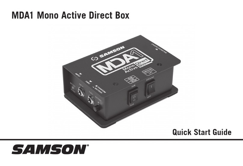
Samson MDA1 User manual

Samson

Samson MDA1 User manual

Samson md1 pro User manual

Samson

Samson md1 pro User manual

Samson S-Gate 4 User manual

Samson

Samson S-Gate 4 User manual

Samson Q2U Recording Pak User manual

Samson

Samson Q2U Recording Pak User manual

Samson SCOM User manual

Samson

Samson SCOM User manual

Samson D1500 User manual

Samson

Samson D1500 User manual

Samson Q2U Recording Pak User manual

Samson

Samson Q2U Recording Pak User manual

Samson Carbon 61 User manual

Samson

Samson Carbon 61 User manual

Samson GRAPHITE M25 User manual

Samson

Samson GRAPHITE M25 User manual

Samson Graphite 25 User manual

Samson

Samson Graphite 25 User manual

Samson MD2 PRO User manual

Samson

Samson MD2 PRO User manual

Samson Signal Processors S3-Way User manual

Samson

Samson Signal Processors S3-Way User manual

Samson C COM16 User manual

Samson

Samson C COM16 User manual

Samson Graphite MD13 User manual

Samson

Samson Graphite MD13 User manual

Samson MD1 Direct Box User manual

Samson

Samson MD1 Direct Box User manual

Samson GRAPHITE M32 User manual

Samson

Samson GRAPHITE M32 User manual

Popular Recording Equipment manuals by other brands

Shinybow USA SB-5430 instruction manual

Shinybow USA

Shinybow USA SB-5430 instruction manual

METASONIX RK2 XS-VCA user manual

METASONIX

METASONIX RK2 XS-VCA user manual

Ecolab OGM Series Configuration manual

Ecolab

Ecolab OGM Series Configuration manual

Gewiss Chorus GW 20 476 manual

Gewiss

Gewiss Chorus GW 20 476 manual

Panasonic AJ-PD500 brochure

Panasonic

Panasonic AJ-PD500 brochure

Brigade MDR-504GW-500 Installation and operation guide

Brigade

Brigade MDR-504GW-500 Installation and operation guide

netvox R718H2 user manual

netvox

netvox R718H2 user manual

KORNEFF PAWN SHOP COMP 2.0 user manual

KORNEFF

KORNEFF PAWN SHOP COMP 2.0 user manual

Comelit 3063D Technical manual

Comelit

Comelit 3063D Technical manual

PRESONUS FIRESTUDIO 26X26 - SCHEMA user manual

PRESONUS

PRESONUS FIRESTUDIO 26X26 - SCHEMA user manual

Lyngdorf MP-40 Management guide

Lyngdorf

Lyngdorf MP-40 Management guide

Mircom QIF-2011 installation manual

Mircom

Mircom QIF-2011 installation manual

PianoDisc Prodigy SDHD II user guide

PianoDisc

PianoDisc Prodigy SDHD II user guide

Yamaha MU100B owner's manual

Yamaha

Yamaha MU100B owner's manual

Enginko MCF-LW06010B manual

Enginko

Enginko MCF-LW06010B manual

Bastl BESTIE Instrument manual

Bastl

Bastl BESTIE Instrument manual

Velleman PCUSBVC2 user manual

Velleman

Velleman PCUSBVC2 user manual

Pulsar INTW manual

Pulsar

Pulsar INTW manual

manuals.online logo
manuals.online logoBrands
  • About & Mission
  • Contact us
  • Privacy Policy
  • Terms and Conditions

Copyright 2025 Manuals.Online. All Rights Reserved.