TECHNICAL BULLETIN 2020-0015
www.SamsungHVAC.com TB2020-0015 (REV 12/15/2020) 4
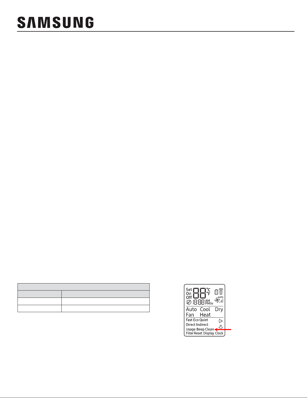
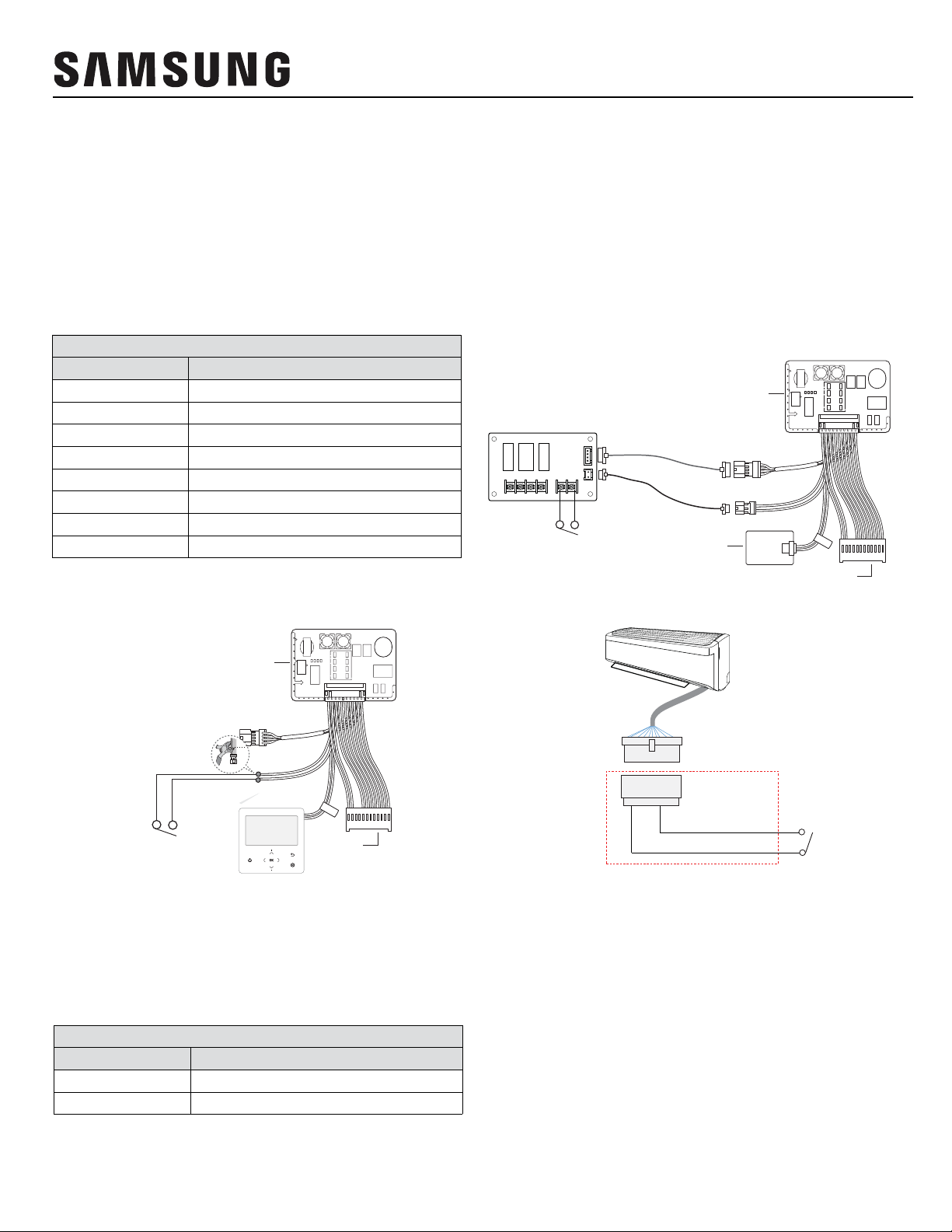
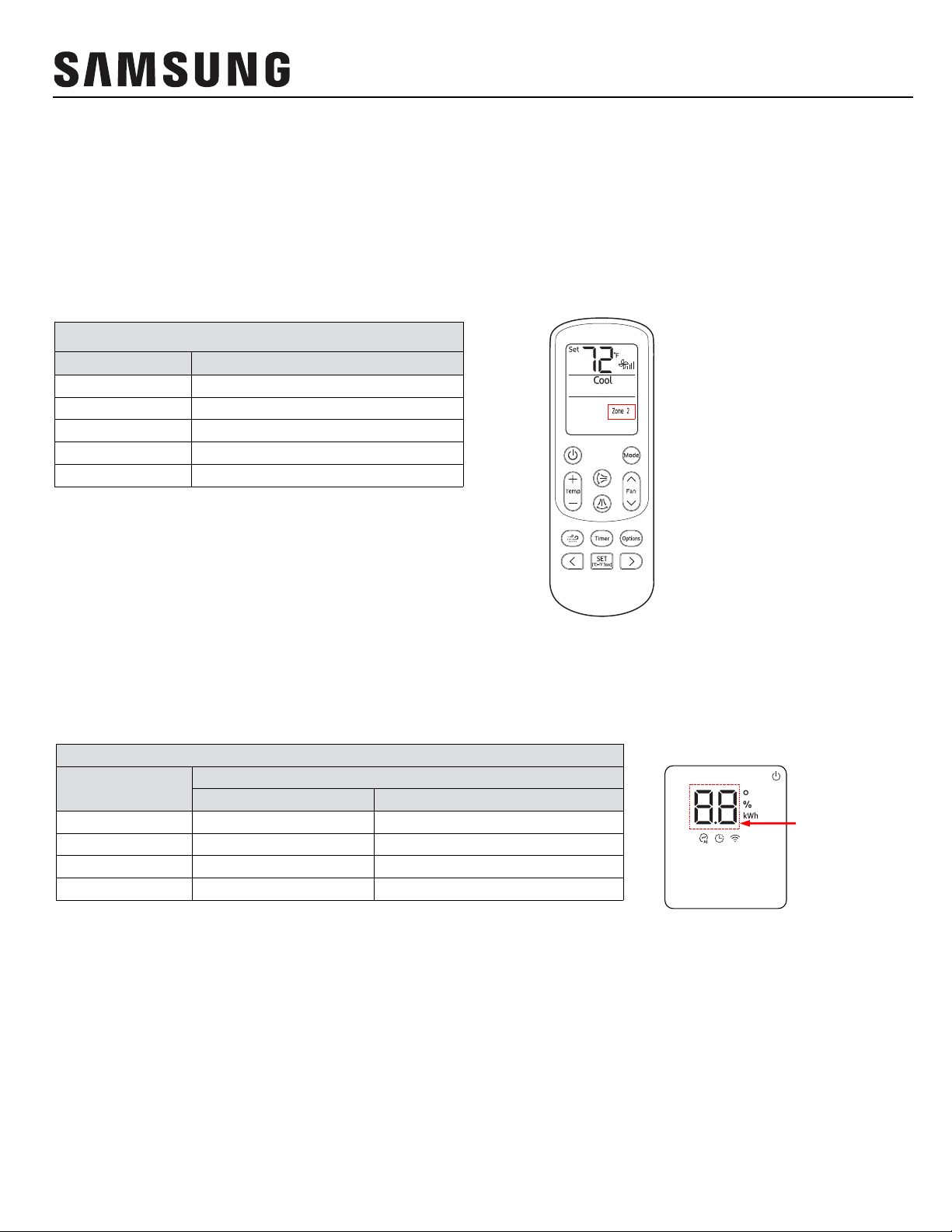
Feature MIM-B14
Terminals Option If Then
Contact Opens - Unit turns OFF
- Controller ENABLED (unit can be turned on via controller)
Contact Closes - Indoor unit turns ON in previous mode
Contact Opens - Unit turns OFF
- Controller DISABLED (unit cannot be turned on via controller)
Contact Closes
(while unit is OFF)
- Unit remains OFF/STANDBY (does not turn on in previous mode)
- Controller ENABLED (controller or schedule event can turn on the
unit)
Contact Opens - Unit turns OFF
- Controller DISABLED (unit cannot be turned on via controller)
Contact Closes
- Unit goes into previous state (STANDBY/operation, plus all
settings)
- Controller ENABLED (unit can be controlled via controller)
External
Contact
Control
5 / 6
ON/OFF Control
OFF-Only
Control ¹
Window ON/OFF
Control
Contact Opens
- Unit turns OFF
- Controller ENABLED (unit can be turned on via controller)
Contact Closes
Contact Opens
(while unit is OFF)
- Unit turns OFF
- Controller DISABLED (unit cannot be turned on via controller)
Contact Closes
Contact Opens
- Unit turns OFF
- Controller DISABLED (unit cannot be turned on via controller)
Contact Closes
ON/OFF
Reverse Control
OFF-Only
Reverse Control ¹
Window ON/OFF
Reverse Control
- Indoor unit turns ON in previous mode
- Unit remains OFF/STANDBY (does not turn on in previous mode)
- Controller ENABLED (controller or schedule event can turn on the
unit)
- Unit goes into previous state (STANDBY/operation, plus all settings)
- Controller ENABLED (unit can be controlled via controller)
¹ Off-only control is ideal for float switch and energy saving device (example: motion sensor, manual timer, etc.) connection.
² External contact control must be enabled. If external contact control is not required, simply install a jumper between terminals 5 and 6.
Feature MIM-B14
Terminals Option If Then
Cooling Thermal-ON - Contact = CLOSED
Cooling Thermal-OFF - Contact = OPEN
Heating Thermal-ON - Contact = CLOSED
Heating Thermal-OFF - Contact = OPEN
FAN mode or STANDBY - Contact = OPEN
Unit ON - Contact = CLOSED
Unit OFF - Contact = OPEN
No error - Contact = CLOSED
Error - Contact = OPEN
Indoor Unit
Operation
Output
3 / 4
Thermal-ON/OFF
Output ²
Operation ON/
OFF Output
Error Status
Output 1 / 2N/A
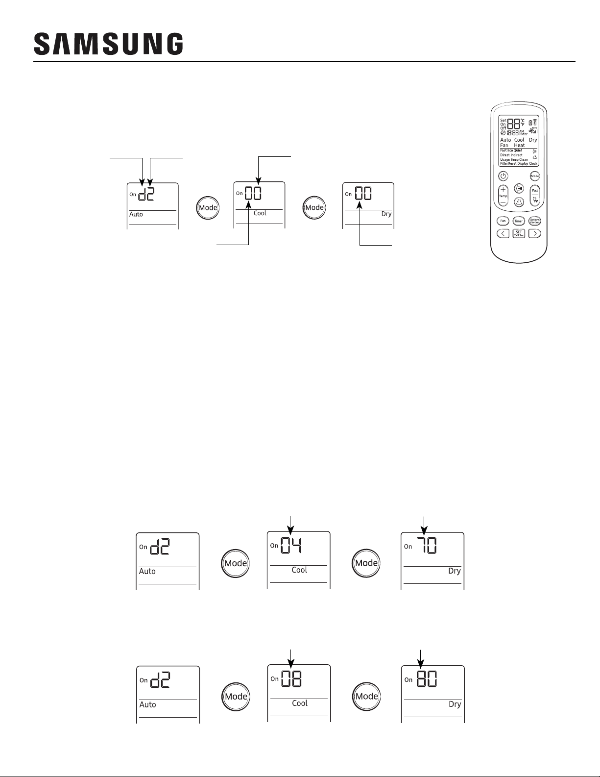
MIM-B14 output
MIM-B14 Input


ME User manual")