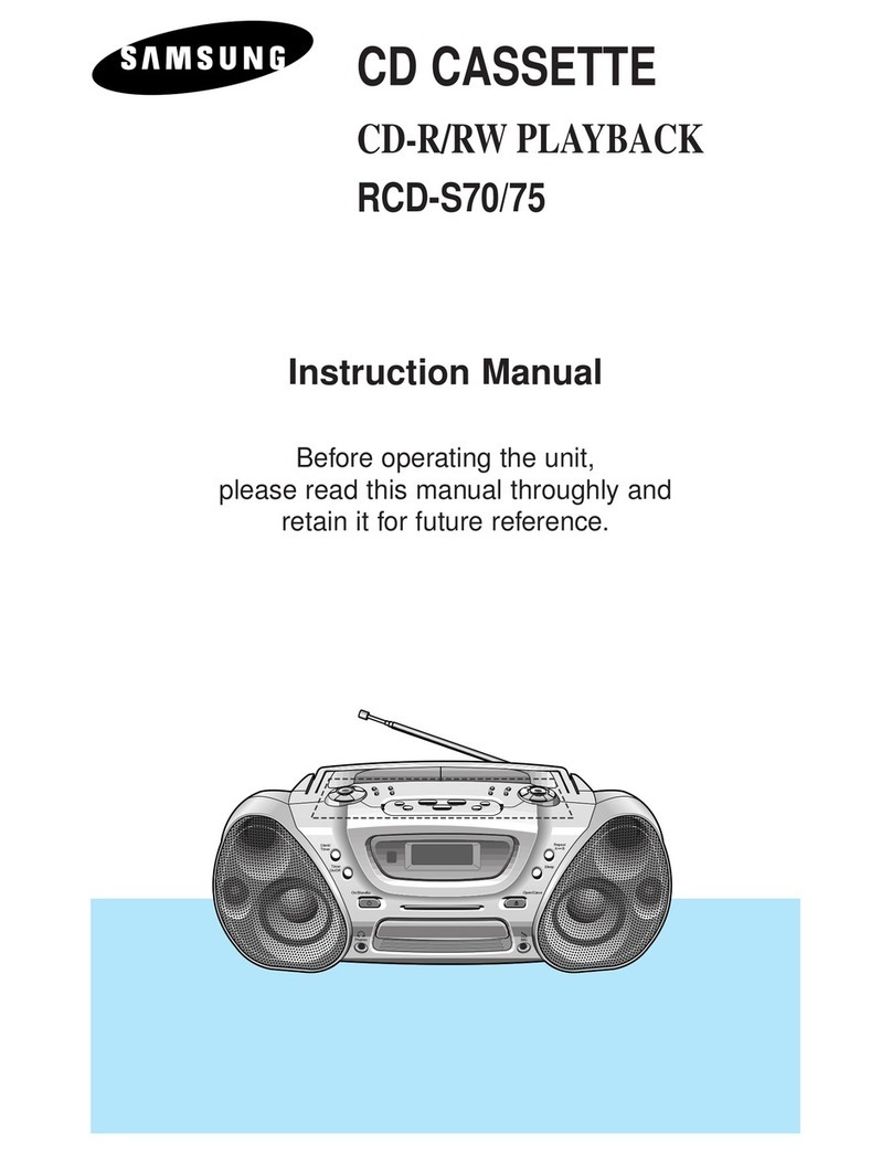
Samsung RCD-2600 User manual

samsunc
|
SERVICE
MANUAL
MODEL:
RCD-2600
Electronics
__
DTS
RADIO
CASSETTE
RD
WITH
COMPACT
DISC
PLAYER
¢
200
29900
oo
Qo0e
@
900
=a
000
SSS
C7
SPECIFICATION
RADIO
Frequency
range
LF
Antenna
TAPE
Track
system
Recording
system
Erasing
system
Monitor
system
Frequency
response
Tape
speed
Tape
drive
system
Tape
loading
system
Motor
system
:
FM:
87.5
—
108MHz
(87.9
~
107.9)
AM(MW):
530
-
1720KHz
(622
—
1611)KHz
LW:
146
-
290KHz
:
FM:
10.7MHz
FM:
Telescopic
rod
antenna
AM(MW)/LW:
Ferrite
bar
antenna
:
4
track
2
channel
:
AC
bias
(DECK
A)
:
Magnetic
erasing
(DECK
A)
:
Variable
monitor
:
Normal
50
—
8000Hz
CrO2/METAL
(PB)
50-10000Hz
:
4.75cm/sec
(Normal
speed)
9.5cm/sec
(High
speed)
:
Capstan
belt
driven
:
Front
loading
:
DC
synchronous
2
speed
motor
(DC
9V)
GENERAL
Frequency
response
:
20-20000Hz
Speaker
:
Woofer:
a
100mm
x
2
(4.9)
SBS
:@
100mm
x
1
(82)
Max
output
:
4W/CH
Power
source
:
AC:
See
label
rating
DC:
12V
(D,
UM1,
HP2)
DC:
6V
(AA
x
4)
—
For
memory
back
up.
Power
consumption
:
30W
Dimension
1
663(W)
x
249(H)
x
247(D)
Weight
:
7.5Kg
(Without
batteries)
Headphone
jack
:
8
3.5mm
COMPACT
DISC
PLAYER
Frequency
range
1
20-20,000Hz
Signal
to
Noise
ratio
:
90
dB
(1KHz)
with
filter
Wow
and
flutter
1
0.001%
D/A
Conversion
2
16
bit
Design
and
specifications
are
subject
to
change
upon
improvement
without
prior
notice.

CONTENTS
@
SAFETY
PRECAUTION
....
SERVICING
NOTES
@
LOCATION
OF
CONTROLS...
DISASSEMBLY
INSTRUCTION
LCD
DISPLAY...
TROUBLE
SHOOTING
CHART......
ADJUSTMENT...
CD
ADJUSTMENT.
IC
AND
TR
LEAD
LAY
OUT.
BLOCK
DIAGRAM...
SCHEMATIC
DIAGRAM
PCB
PATTERN
&
MARKING
DIAGRAM
EXPLODED
VIEW...
DECK
EXPLODED
VIEW
(CD
&
CASSETTE)...
CASSETTE
DECK
PARTS
LIST.
CD
DECK
PARTS
LIST.
PARTS
LIST.
ABBREVIATION
LIS
TROUBLE
SHOOTING
(CD)
a
a
a
a
a
a
a
ti
@
WIRING
DIAGRAM......
a
a
Ld
a
a
a
a
a
BASIC
CIRCUIT
OPERATION...

Hi
SAFETY
PRECAUTION
1.
CLASS1
LASER
PRODUCT
This
compact
disc
player
is
classified
as
a
CLASS
1
laser
product.
2.
LASER
WARNING
LABEL
The
label
shown
below
may
be
affixed
or
not
according
to
country.
(UL)
(CSA)
(EU)
This
Produc.
Compiles
with
CERTIFIED
ONLY
TO
CANADIAN
DHHS
Rules
21CFR,
Sub
ELECTRICAL
CODE.
CLASS
1
chapter
J.At
date
of
Manu-
facture.
CERTIFIE
EN
VERTU
DU
CODE
LASER
PRODUCT
CANADIAN
DE
LELETRICITE
SEULEMENT
Location
:
Enclosure
back.
(SCAN)
(EU)
‘ADVARSEL:
USYNLIG
LASERSTRALING
VED
UL
:
Manufactured
for
U.S.A.
Market.
ABNING,
NAR
SIKKERHEDSAFBRYDERE
ER
CSA:
Manufactured
for
Canadian
Market.
nen
plea
ONDGK)
UODGAETTELSE
EU
:
Manufactured
for
European
Market
SCAN
:
Manufactured
for
Scandinavian
Market.
Location
:
on
the
disc
clamper
ol
inner
side
of
CD
door
or
nearby
CD
chassis.
3.
LASER
BEAM
WARNING
ADVERSEL—
USYNLIG
LASERSTRALING
VED
ABNING,
NAR
SIKKERHEDSAFBRYDERE
ER
UDE
AF
FUNKTION.
UNDGA
UDSAETTELSE
FOR
STRALING.
VARNING—
—
OSYNLIG
LASERSTRALNING
NAR
DENNA
DEL
AR
OPPNAD
OCH
SPARR
AR
URKOPPLAD.
STRALEN
AR
FARLIG.
VARITUS—
—_LAITE
SISALTAA
LASERDIODIN,
JOKA
LAHETTAA
NAKYMATONTA
SILMILLE
VAARALLISTA
LASERSATEILYA.
CAUTION—
INVISIBLE
LASER
RADIATION
WHEN
OPEN
AND
INTERLOCKS
DEFEATED.
AVOID
EXPOSURE
TO
BEAM.
4,
LASER
DIODE
SPECIFICATION
(OPTICAL
PICK-UP)
°
Material:
AlGaAs
Wavelength:
760-800mm
Emission
duration:
Continuous
Laser
Output:
0.2mW
*
This
output
is
the
value
measured
at
distance
1.6mm
from
the
objective
lens
surface
on
the
optical
pick-up
block.
Classification:
CLASS
1
5.
WARNING
FOR
SERVICING
WARNING:
When
servicing,
do
not
approach
the
LASER
exit
with
the
eye
too
closely.
In
case
it
is
necessary
to
confirm
LASER
beam
emission,
be
sure
to
observe
from
a
distance
of
more
than
30cm
from
the
surface
of
the
objective
lens
on
the
optical
pick-up
block.
VARNING:
Nar
underhaliningsarbeten
utférs,
narma
dig
férsiktigt
och
se
inte
pa
laserutstralningen
pa
for
nare
hall.
Ifall
det
ar
nédvandigt
att
betrygga
laserstralens
utstrémning.
Var
saker
att
kontrollera
detta
fran
ett
avstand
av
mer
an
30cm
(11.81
inch.)
fran
den
objektiva
linsens
yta
pa
den
optiska
utsandningspunkten.
ADVARSEL:
_Nar
repareringsarbejdet
udfoeres,
naerm
dig
forsigtigt
og
se
ikke
pa
laserudstralingen
pa
for
naer
hand.
It
ilfaeldet
at
det
er
noedvaendigt
at
bestemme
laserstralens
udstraling.
Vaer
sikker
pa
kontrollere
dette
fra
en
afstand
af
mere
end
30cm
(11.81
inch.)
fra
den
objektive
linses
overflade
pa
den
optiske
udsendningspunkt.
VAROITUS:
Silmia
on
varottava
viemasta
liian
labeiie
Laser-poistokanavaa
huoiion
aikana.
Jos
on
valttamaténta
varmistaa
Laser-Sateen
paastd,
pysyttels
sit
tarkasteltaessa
vahintaan
30cm
etaiyydella
optisen
lukon
objecktiivilinssin
pinnasta.
eoo000

Wi
SERVICING
NOTES
Disconnect
power
supply
cord
before
separating
cabinet
for
servicing
as
you
may
experience
an
electric
shock.
Avoid
repairing
under
direct
sunshine
and
heat
which
may
cause
cabinet,
transistor
and
IC
to
be
transformed
or
misoperate.
Use
a
soft
cotton
swab
moistened
with
warm
water
or
neutral
cleaner
when
parts
of
a
unit
need
to
be
cleaned.
Be
sure
to
use
identical
and
standardized
replacement
parts,
especially
for
critical
parts
marked
by
A\
in
the
circuit
diagram
and
arts
list.
‘avoid
repairing
the
set
near
a
TV
or
any
other
magnetic
forces.
Disconnect
the
plug
from
wall
socket
during
electric
storm
to
reduce
the
risk
of
damage.
Be
careful
of
electrostatic
damage
when
replacing
the
control
IC
such
as
u-COM,
LSI
and
pick-up.
Pons
Noa
HANDLING
THE
OPTICAL
PICK-UP
*
The
laser
diode
in
the
optical
pick
up
may
suffer
electrostatic
breakdown
because
of
potential
static
electricity
from
clothing
and
your
body.
The
following
method
is
recommended.
Place
a
conductive
sheet
on
the
workbench.
(The
black
sheet
used
as
wrapping
for
repair
parts.)
Place
the
set
on
the
conductive
sheet
so
that
the
chassis
is
grounded
to
the
sheet.
Place
your
hands
on
the
conductive
sheet.
(This
gives
them
the
same
ground
as
the
sheet.)
Remove
the
optical
pick
up
block.
Perform
work
on
top
of
the
conductive
sheet.
Be
careful
not
to
let
your
clothes
or
any
other
static
sources
touch
the
unit.
9
FON>
Be
sure
to
put
on
a
wrist-strap
grounded
to
the
sheet.
Be
sure
to
lay
a
conductive
sheet
made
of
copper
etc.
which
is
grounded
to
the
table.
>
@
Wrist-strap
ot
for
grounding
ima
The
unit
@
Conductive
sheet

Hi
LOCATION
OF
CONTROLS
FRONT
panel
123
4
5 6
7
8
91011
12
16|18
|20)22
13°
1415
17 19
21
23
Rear
panel

<FRONT
Panel>
12.
13.
14.
ZSSoemengoanpwones
«
[VOLUME]
Control
.
[Super
Bass
Sound]
Control
.
[GRAPHIC
EQUALIZER]
Control
HANDLE
.
[CD
MULTI
FUNCTION]
Display
ROD
ANTENNA
REMOTE
SENSOR
CD
Door
.
CD
DOOR
PUSH
OPEN
Button
.
[DTS/CLOCK]
Display
DTS/CLOCK
operation
Buttons
[TUNING
UP
DOWN/HOUR
MIN]
Button
[BAND]
Button
[FM
MODE]
Button
{[PROG.]
Button
(Memory/clock
Adjustment)
[AUTO]
Button
[PRESET
STATIONS]
Button
CD
Operation
Buttons
[+10]
Button
[NEXT/FF]
Button
BACK/FB]
Button
PROGRAM]
Button
[DISPLAY]
Button
MODE]
Button
[STOP/CLEAR]
Button
PLAY/PAUSE]
Button
PHONES}
Jack
15.
16.
17.
18.
19,
20.
21.
22.
23.
[POWER]
Button
[WIDE]
Button
[DUBBING]
Button
[TAPE
SELECTOR/BEAT-CUT]
Button
FUNCTION
Buttons
(CD,
TAPE,
TUNER]
DECK
Operation
Buttons
[RECORD]
Button
(A
DECK)
[PLAY]
Button
[REW]
Button
[F.FWD]
Button
[STOP/EJECT]
Button
[PAUSE]
Button
[CLOCK]
Button
[TIMER
ON]
Button
[SLEEP]
Button
<Rear
Panel>
24.
25.
26.
27.
28.
29.
[MIC
MIXING]
Jacks
[CD-OUT]
Jacks
Battery
Compartment
VOLTAGE
SELECTOR
Switch
(Option)
[AC
POWER]
Socket
BATTERY
ON/OFF
Switch

<TUNEP/CLOCK=>
Display
1.
[FM/MW(AM)/W)]
Indicator
.
[FREQUENCY/CLOCK]
Indicator
.
[MEMORY/NUMBER]
Indicator
.
[MEMORY]
Indicator
.
[TIMER/SLEEP/STEREO/AUTO/MONO]
Indicator
.
[AM/PM]
Indicator
(2
BAND)
aPRwWN
2
<CD
MULTI
Function]
Display
7.
[
D>]
Indicator
8.
[
00]
Indicator
9.
[INTRO/SHUFFLE/PROGRAM/
REPEAT/ALL]
Indicator
10.
TRACK
NO
Indicator
11.
Time
Indicator
12.
TRACK
NO
Indicator
13.
SYNCHRO
Recording
Indicator
<REMOTE CONTROL
UNIT>
1.
INFRARED
TRANSMITTER
WINDOW
.
POWER
ON/OFF
BUTTON
.
FUNCTION
BUTTONS
.
PRESET
BUTTONS
.
BAND/SLEEP
BUTTONS
.
CD
CONTROL
BUTTONS
PLAY/PAUSE
BUTTON
SKIP
BUTTON
STOP
BUTTON
7.
FREQUENCY
UP/DOWN
BUTTONS
.
VOLUME
UP/DOWN
BUTTONS
9.
BATTERY
COMPARTMENT
OPaAPon
@

i
DISASSEMBLY
INSTRUCTION
CD
PACK
ASSY
FRONT
ASS'Y
SBS
ASS'Y
BACK
CABINET
BACK,
FRONT
CABINET
a
|
POWER
PCB
G/EQ
PCB
FRONT
P.C.B
MAIN
PCB
1.
FRONT
&
BACK
CABINET
10)
®
®©
® @
|
DECK
ASSY
SBS
SPEAKER
|
1)
Remove
12
screws
(1)
and
2
screws
(2)
and
pull
the
front
cabinet
towards
you
and
disconnect
connector.
2)
Remove
2
screws
(3)
and
pull
off
EQ
and
Volume
knob
and
pull
G/EQ
PCB
towards
you.
3)
Remove
2
screws
(6)
and
pull
power
PCB
towards
you.

2.
CD
pack
Ass'y
e
Just
push
the
CD
Pack
Ass'y
back
to
split
from
the
Front
Cabinet
3.
SBS
Ass'y
Remove
4
screws
(4)
and
4
screws
(5)
from
the
FRONT
CABINET.
9
®@
@ @
4.
Deck
Main
PCB
and
Front
PCB.
1.
DECK
Remove
6
screws
and
disconnect
connectors
2.
Main
PCB
Remove
3
screws
(8)
3.
FRONT
PCB
Hold
Front
PCB
by
the
side
and
lift
up
5.
SBS
Speaker
1.
Remove
speaker
connector-wire
from
Main
PCB.
2.
Remove
connector-wire
from
SBS
chassis.
3.
Remove
10
screws
(9)
from
SBS
chassis.

i
LCD
DISPLAY
If
one
or
all
of
the
LCD
Segments
don't
work,
check
Connection
IC
and
LCD
pins
refering
to
the
Segment
Chart.
1.
TUNER
LCD
|
PIN
NO
1
2 3 4
5
6
|
7 8
9
10
|
11
12
13
14 15
|
16
COM
1
COM
|
—
AM2)
|
MW
|
SW
sreReo|
PM
|
1b
tc
|
2e
|
af
2a
|
2d
|
3e
3f
3a
—
COM
2
[-
COM
|
FM2)
|
FM)
|
LW
am
|
—
|tadeg]
COL|
2g
|
2b
|
—
|
2c
|
3g
3b
-
PIN
NO
|
17 18
19
20
21
22
|
23
24
|
25
|
26
|
27
|
28
|
29
|
30
31
coM1
ad
|
4e
|
4
|
4a
|
4d
|
5q
|
sbe|KHz
|uenony
O
|
7a
|
ze
|
7
|
7a
[Mono
a
4
COM
2
3c
4g
|
4b
-
4c
|
Sacdf
|
—
|
MHz
|
AOTO|
6bc
|
7c
|
7g
|
7b
|SLEEP]
—
Br
aan,
a
a &
iw
|
[sw]
5
Ble
[ean
PAM)
eae
a
a
LEM
TAM
2
=
AUTO
Cea}
72.
He
-LEM}
FAM
MEMORY
Crm
aa]
GEES)
EES
BoE
|

2.
CDLCD
IN
NO
1
Pll
ee
SHUFFLE
[SHUFFLE
PROGRAM|
|REPEAT]
||
ALL
TMIN
I I
SECT
SYNC
OVER
7
IES
Fads]
|
LUN
Fe
7
siete
dito:
5 6
NH
HATH
Shh
45}
—10—

Mi
TROUBLE
SHOOTING
CHART
1.
AC
POWER
INSENSIBLE
Check
AC
Cord
Connection
fo
Check
setting
of
voltage
selector
Switch
(Option)
fe
2.
BATTERY
POWER
INSENSIBLE
Check
Proper
Polarity
}———-————
Install
battery
Properly
|
Check
if
AC
Cord
is
plugged
in
x
-+——}
Unplug
x
Check
voltage
of
CON603
(Power
PCB)
te)
Check
F801
Fuse
}——
Replace
Fuse
fe)
il
Check
CLOCK
oO
1
x
power
S/W
on
-—————}
Check
DC
ON/OFF
Switch
x
@
Check
Connection
of
CON603
and
Soldering
@
Check
Voltage
of
IC801
output
(5V)
Check
voltage
at
IC901
PIN13
Check
voltage
at
base
of
Q808
x
Check
voltage
at
collector
of
Q60!
}————
Replace
Q601
3.
RECORDING
NOT
WORKING
xX
Check
Rec
Bias
Supply
|}——+|
Check
voltage
of
L501
or
Q504
ah
|
Check
Connection
of
rec-head
wire
and
soldering
1°
Check
#
signal
is
supplied
to
1C301
REC
IN
(NO
11.14)
Jo
Check
voltage
?
==

4.
NO
OUTPUT
x
Check
if
Power
LED
lights
Refer
to
"BATTERY
POWER
INSENSIBLE"
ie)
x
Volume
is
set
to
lowest
Raise
Volume
oO
Check
Voltage
of
Power
IC
(IC601,
602)
pins
Replace
IC.
°
y
Check
Connection
of
CON701
and
Soldering
|
°
y
Check
Volume
Input
voltage
through
IC601,
602
|
5.
COMPACT
DISC
INOPERATIVE
x
Check
if
LCD
lights
@
Check
Leaf
Switch
contacts
of
CD
Door
____,______
@
Check
Connection
of
CW106
and
soldering
Check
Disc
Rotation
9
x
x
|
Check
Voltage
at
emitter
of
Q810
Replace
Q810
or
ZD819
°
fe}
Make
CD
pack
adjustment
—12—

6.
TAPE
NOT
WORKING
x x
Check
if
Tape
plays
|
++
Check
voltage
Motor
a
Check
Contact
of
Deck
Leaf
Switch
fe}
Check
Output
of
Deck
A,
B
ie)
Insensible
Completely
ie)
Check
Voltage
at
IC301
pin
18
Check
Connection
of
EQ
B:
line
fe)
¥
x
Check
Voltage
at
IC301
other
pins
}-——————————»
Replace
IC.
fe}
Y
Check
Connections
from
EQ
Output
through
IC601,
602
@
DECK
A
INOPERATIVE
A
x
Check
Connection
of
Connect
Properly
PP
head
con-wires
fe}
x
Deck
B
buttons
are
all
off
-_------__—_—_»
Set
all
functions
to
off
fe}
en
ee
5
x
Deck!
eet
Switch
Open
Leaf
Switch
@
DECK
B
INOPERATIVE
x
Check
Connection
of
Play
Head
con-wires
}—————
Connect
Properly
Check
Voltage
at
pin19
of
IC301
|
Check
Voltage
Supply
of
Circuitry
—13—

7.
RADIO
INSENSIBLE
x
Check
Voltage
of
L105
|}___—____+|
Check
voltage
of
power
Supply
Circuitry
fe}
x
Check
Voltage
at
IC201
all
pins
@
Check
Connection
of
Tuner
B°
line
@
Replace
IC
x
Check
noise
Check
Voltage
at
FP1
Le
pin
4
°
+f
Y
Check
Connection
of
Rod
Antenna
@
AMINSENSIBLE
fe}
x
Check
FP1
Replace
FP1
Check
noise
fe}
fe}
Check
Connection
of
CONO1
and
soldering
Jo
Check
Voltage
at
Collector
Check
AM
ADJUSTMENT
of
a
103,
104
oO
Replace
1C901
—14—

HE
ADJUSTMENT
ADJUSTMENT
PROCEDURE
INSTRUMENT
AND
TOOLS
.
FM,
AM
STANDARD
SIGNAL
GENERATOR
(SSG)
.
OSCILLOSCOPE
.
FREQUENCY
COUNTER
VTVM
.
LOOP
ANTENNA
DUMMY
LOAD
(4
OHM)
.
DIGITAL
TESTER
NOgPpons
BEFORE
MAKING
ADJUSTMENT
1.
Check
the
power
source
voltage.
2.
Select
desired
Band
and
Function.
3.
Set
Tone
Control
at
mid
position
4.
Modulate
AM
to
30%
amplitude
with
400Hz
signal
and
FM
to
22.5MHz
deviation
with
400Hz
signal.
5.
Set
Volume
Control
to
approximately
S0mW
(40hm)
@
ADJUSTMENT
POINT
LOCATION
(AUDIO
SECTION)
MAIN
PCB
(PARTS
SIDE)
e@
7105
:
AMANT
TRIMMER
(1404KHz:
2BAND)
e@
1102
AMASC
TRIMMER
(1611,
1720KHz)
e@
1104
AM
ANT
TRIMMER
(1404KHz)
e
L102
AM
OSC
COIL
(522,
530KHz)
e
L101
AM
ANT
COIL
(594KHz)
e
L501
:
REC
BIAS
COIL
(85KHz)
—15—
LW
ANT
TRIMMER
(270KHz)
LW
OSC
TRIMMER
(295KHz)
LW
OSC
COIL
(146KHz)
LW
ANT
COIL
(164KHz)
AM
IFT
COIL
(594KHz)
SPEED
CONTROL
(2985KHz)

1.
MW(AM)/LW
ADJUSTMENT
ITEM
CONNECTION
STEP
|
S.S.G
RADIO
Freq.
Adjustment
Point
RESULT
Frequency
Setting
1
522(530)KHz
522
or
S30KHz
L102
D/TESTER:
AM
OSC
coil
1.2
+
0.05V
MW(AM)
FREQUENCY
Fig.
2
2
1611(1720)KHz
1611
or
1720KHz
T102
D-TESTER:
RANGE
AM
OSC
trimmer
7.8
+
0.05V
3.
Repeat
steps
2
and
3
several
times.
IF
Fig.
1
4
594KHz
594KHz
T201
Maximum
AM
IFT
coil
output
5
594KHz
594KHz
AM
AN
coil
Maximum
L101
output
MW(AM)
Fig.
2
TRACKING
6
1404KHz
1404KHz
AM
ANT
trimmer
Maximum
(1104)
output
ae
Repeat
steps
5
and
6
several
times
8
146KHz
146KHz
L104
D-TESTER:
LW LW
OSC
coil
0.9V
+
0.05V
FREQUENCY
Fig.
2
RANGE
9
290KHz 290KHz
T103
D-TESTER:
LW
OSC
trimmer
4.95V+0.05V
10
Repeat
steps
8
and
9
several
times
an)
170KHz
170KHz
L105
Maximum
LW
ANT
coil
output
LW
TRACKING
Fig.
2
12
250KHz
250KHz
T101
Maximum
LW
ANT
trimmer
output
13
Repeat
steps
11
and
12
several
times
2.
FM:
NO
ADJUSTMENT
DIGITAL-TESTER
MAIN
PCB
Fig.
1
osc
VIvM
LOOP
ANT
MAIN
PCB

3.
TAPE
SECTION
1.
RECORDING
BIAS
ADJUSTMENT
a)
Connect
the
frequency
counter
to
JW88
of
L501
(Bias
Coil)
as
shown
in
the
figure
3.
b)
Press
[RECORD]
button
(
@
)
of
DECK
A
and
adjust
L501
so
the
frequency
Counter
reads
reads
85KHz.
2.
TAPE
SPEED
ADJUSTMENT
a)
Connect
the
equipments
as
Fig.
4
to
adjust
the
tape
speed
with
test
tape
[recorded
at
3KHz,
MTT-111N]
in
DECK
B.
b)
Adjust
the
semifixed
resistor
(SVR801)
so
that
the
frequency
counter
reads
2985Hz
+
10Hz.
c)
Insert
a
test
tape
into
DECK
A
and
check
if
the
frequency
counter
reads
2985Hz
+
10Hz.
3.
TAPE
AZIMUTH
ADJUSTMENT
a)
Connect
the
equipments
as
Per
Fig.
5
to
adjust
the
tape
azimuth
with
test
tape
(recorded
at
10KHz
MTT-114N).
b)
Press
play
with
loading
a
test
tape
in
deck
A
and
set
Volume
Control
approximately
SOmW,
(4
OHM.)
¢)
Adjust
the
azimuth
adjustment
screw-of
left
side
of
record/play
head
for
maximum
output
and
for
the
same
channel
phase.
(See
fig.
6)
d)
Repeat
steps
a,
b,
c
in
deck
B.
e)
Secure
adjustment
screw
with
glue
after
adjustment
is
complete.
ADJUSTMENT
MAIN
PCB
Frequency
Counter
68k
85KHz
Jwes
+
SVR801
MAIN
PCB
Fig.3
>
Fig.4
R/P
HEAD
ADJUSTMENT
SCREW

@
CD
ADJUSTMENT
1)
CLV
ADJUSTMENT
10:
1
damping
probe.
A.
Turn
power
on
without
loading
a
disc.
.
Connect
S2
(Asymetry
;
short)
-
Connect
TPS
to
GND
and
TP?
to
Positive
terminal
on
the
Frequency
Counter.
.
Adjust
VR
1702
so
that
the
Frequency
Counter
reads
4.460MHz
+
(0.01MHz).
-
Disconnect
$2.
moow
33
Asymetry
point
GND
port
of
FREQ.
COUNTER
Positive
port
of
CLV
adjustment
FREQ.
COUNTER
—
18—

2)
EF
BALANCE
ADJUSTMENT
(Power
On)
..
Set
Oscilloscope
Time/Div
to
2mS.
Set
Oscilloscope
Volt/Div
to
0.5V.
.
Connect
TP1
(Vref)
to
GND
and
TP4
(T.E)
to
positive
terminal
on
the
oscilloscope.
.
Press
PLAY
with
loading
a
disc.
.
Turn
VR1704
all
the
way
counter
clockwise.
(Sound
comes
out
abnormally
and
discontinuously.)
.
Adjust
VR1701
so
that
the
waveform
is
equally
symmetrical
above
and
below.
(A
=
B)
.
Turn
VR1704
to
play
sound
normally.
(Nearly
mid-positon
of
VR1704)
oanmoomPr
|
EF
Balance
adjustment
Negative
port
of
oscilloscope
Positive
port
of
oscilloscope
© ©
Ag
2s
Table of contents
Other Samsung Cassette Player manuals

Samsung
Samsung RCD-1230 User manual

Samsung
Samsung SV-A10G User manual

Samsung
Samsung S75RCD-S70 User manual

Samsung
Samsung RCD-S50 User manual

Samsung
Samsung VR9070 User manual

Samsung
Samsung CXJ1331/TUCX User manual

Samsung
Samsung CXJ1331/TUCX User manual

Samsung
Samsung RCD-S70 User manual

Samsung
Samsung SV-631 User manual
Samsung
Samsung TW20P14X/BWT User manual