Safety Warnings
Read all Warnings and Cautions noted blow.
Failure to do so could result in serious or fa-
tal injury.
Prior to installation of this unit, carefully
read and adhere to all CAUTION,
ATTENTION, and ADVICE notices located
throughout this manual. Failure to comply
with these instructions can cause serious in-
jury, death, or damage to the unit.
RISK OF SUCTION ENTRAPMENT
HAZARD, WHICH, IF NOT AVOIDED CAN
RESULT IN SERIOUS INJURY OR DEATH.
Do not block pump suction at the pump or in
the pool as this can cause severe injury or
death.
Electrical wiring MUST be installed by a
trained professional and adhere to local
code and regulations.
Avoid electric shock. DO NOT USE pow-
er extension cords.
Connect ONLY to a Ground-Fault Circuit
Interrupter (GFCI) power outlet. Consult a
Qualified professional electrician for safe
and proper installation of a qualified electri-
cal outlet.
Incorrectly installed equipment may fail,
causing severe injuries or damage to the
pump-filter system.
Never submerge the filter and/or pump in
water.
Never place the pump or filter in your
pool.
Trapped air in the pump-filter system may
cause the TANK COVER to be blown off
which can result in death, serious injury, or
damage to the pump-filter system. Ensure
all air is out of system before operating.
NEVER change the 7 Position Multi-Port-
Valve while the system is operating.
ALWAYS unplug the system before
changing the control valve.
Install this product with a sufficient safety
margin from the pool to prevent children
from using the system to access the pool.
Never PLUG or UNPLUG this unit from
an electrical source while standing in water.
NEVER service this unit with the electrical
power cord connected.
Do NOT operate the system while the
pool is being used.
KEEP CHILDREN AWAY from all electri-
cal equipment.
NEVER ALLOW CHILDREN TO
OPERATE THIS EQUIPMENT.
The Pool Owner should always exercise
caution and common sense when utilizing
their swimming pool and operating equip-
ment.
Generel Information
This manual provides information relating to the installation, utiliza-
tion and maintenance of our filtration system. We recommend that
you read this manual in its entirety and keep it for future reference.
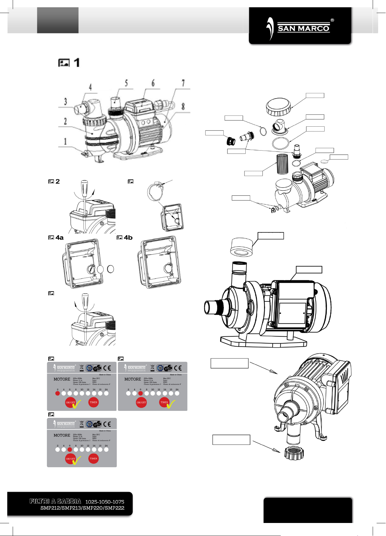
The pump included with the filtration system is a horizontal, self-
priming centrifugal pump. For the pump to function correctly, the wa-
ter temperature must not exceed 35°C /95°F. The materials used in
the pump have undergone stringent hydraulic testing and electrical
inspections.
The filter included in the filtration system consists of high-grade pol-
ypropylene (PP). It is seamless and manufactured as a single unit
(absolutely corrosion resistant and resistant to commercially availa-
ble swimming pool chemicals). (Prerequisite: Compliance with the
standard recommended specifications for the pH- and chlorine-
value). It is equipped with a container drainage system, pressure
gauge, built-in container components, e.g.bottom strainer for even
water distribution and a stable PE separation wall between the filter
and the fresh water chamber. The filter container comes ready to
plug-in and is supplied with a user-friendly 7 Position Multi-Port
Valve integrated into the tank cover, an approved filter pump with
hair and lint basket, and a plastic base for ready on-site mounting.
Read this manual carefully before installation. The filtration system
and pump must be installed in accordance with the standards in ef-
fect.
We decline all responsibility for the consequences of failure to com-
ply with the installation instructions. We recommend that you comply
with the power source instructions to avoid overloading the pump
motor and/or electric shock.
This filtration system is not intended for use by persons with reduced
physical, sensory or mental capabilities, or lack of experience and
knowledge.
Safety notes and callout boxes should always be observed.
Safety Notes
Your filter pump was constructed and tested
and left the manufacturing plant in technically
operational condition. In order to maintain this
condition and ensure safe operation, the user
should observe the notes and product infor-
mation contained in this technical handbook.
If there is any indication that safe operation is
no longer possible, the device is to be dis-
connected from the power supply and se-
cured against accidental use.