Hytek ALPHA/50WAFC Instruction manual

S886/3
Technical Data
ALPHA EX & MIR APPROVED DIESEL
PUMP WITH FUEL CONTROL SYSTEM
Applies to the following models only:
- ALPHA/50WAFC - ALPHA/70WAFC - ALPHA/90WAFC
Please read carefully before commencing installation
Registered Office: HYTEK (GB) LIMITED, Delta House, Green Street, Elsenham, Bishop’s Stortford
CM22 6DS UK. Registered in England No. 1915382
Web: www.hytekgb.com

S886/3
ENVIRONMENTAL INFORMATION
UK Regulation SI/2013/3113 requires that the equipment
bearing this symbol on the product and/or its packaging
must not be disposed of with unsorted municipal waste.
The symbol indicates that this product must be disposed of
separately from regular household waste streams. It is
your responsibility to dispose of this and other electric and
electronic equipment via designated collection facilities
appointed by the government or local authorities.
PRODUCT DESCRIPTION
This pump is ATEX certified to dispense diesel or other liquids classed as
category 3 in accordance with European Regulation No. 1272/2008. It
bears the following certification marking and number:
This pump is MID certified in accordance with OIML to dispense
diesel or other liquids in viscosity class 2. It bears the following
certification marking and number:
UK/0126/0240
II 2 G
MANUFACTURED TO: EN13617-1
CERTIFICATE NO: CML 15ATEX9183
2776

S886/3
IMPORTANT WARNING NOTES
1. On above ground storage tanks, an angle check valve fitted with the
appropriate spring or pressure regulating valve must be fitted at the
tank outlet to prevent loss of fuel under gravity in the event of
vandalism or accidental damage.
2. This pump must only be used to dispense diesel or other liquids
classed as category 3 in accordance with European Regulation No.
1272/2008. It must not be used to dispense petrol or any other liquid
with a similar flash point.
3. Installation of this equipment and its associated tank, pipe work and
fittings should only be carried out by qualified fuel installation
engineers.
4. The installation must be carried out in accordance with the
requirements of EN 60079-14 and the latest relevant electrical and
local authority regulations and standards.
5. It must not be used with other liquids or for other applications. We will
accept no warranty claims or liability if it is used for other liquids or
applications.
6. Minimum delivery is 2 litres. See that indication is ZERO before delivery
commences. For attended service a delivery can only be authorised
after settlement of the previous transaction.
7. The pump must be located and installed in a climatic environment in
accordance with the following:
Temperature : -20°C to +45°C
Humidity : Class H3 (open location with
averageclimatic conditions)
Environment : Open and condensing
Mechanical : Class M1 (location with vibration of
low significance)
Electrical Disturbance : E1 (located in residential, commercial
and light industrial environments)

S886/3
INSTALLATION INSTRUCTIONS
1. Check you have the following items:
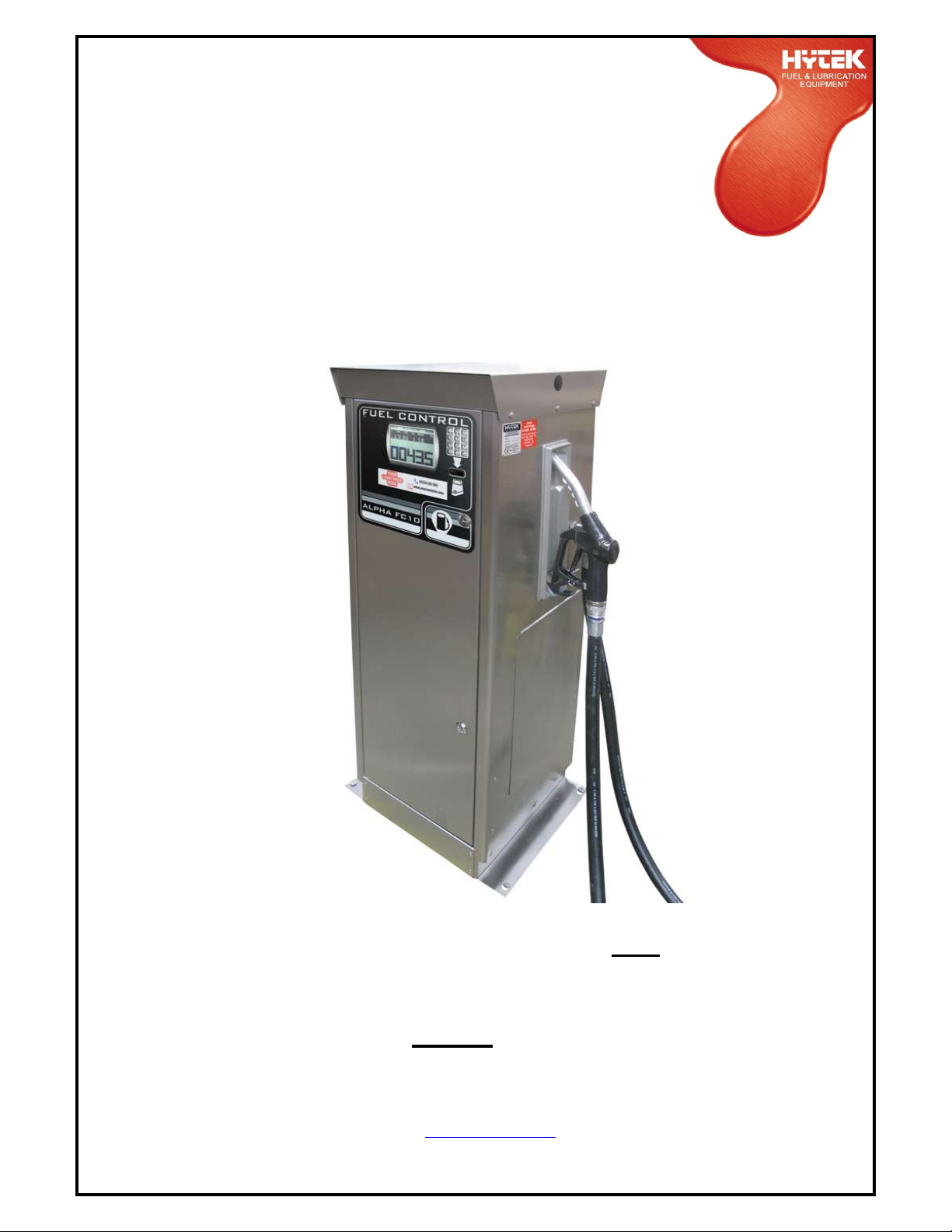
1 off Alpha FC10 pump
1 off delivery hose
2 off front door keys
2. Open the front panel using the key provided.
3. Remove the rear panel, if necessary, and store safely.
MOUNTING
4. Bolt the pump to a firm level foundation by means of the four 14 mm
diameter-mounting holes provided.
NB: If the optional drip tray is to be fitted to the pump it must be
sealed to its foundation, with a suitable elastomeric substance,
to prevent leaked fuel "wicking" back underneath the pump. To
maintain the environmental integrity of the drip tray any possible
leak path through the pump mounting holes must also be
sealed.
PIPEWORK
5. Connect the 11/2” diameter pipe from the tank to the suction inlet
flexible connector of the pump. The inlet thread of the flexible
connector flange is 11/2” BSP taper female. Seal the joints with a
suitable thread sealing compound. The pipe work must be sealed to
the drip tray (if fitted) to ensure no leaking fuel can flow underground.
An alternative pipe work entry point, for above ground pipe work, is
provided at the rear of the pump base. Push out the plastic cover
plate if required.
NB: On above ground tanks an angle check valve fitted with the
appropriate spring or an anti-syphon valve must be fitted in the
suction line to prevent spillage or leakage in the event of damage.
6. Connect one end of the delivery hose into the outlet elbow. Ensure the
hose-sealing washer is in place on the hose end. It should be hand
tight plus a quarter turn.
7. Screw the nozzle onto the other end of the hose, again ensuring the
washer is in place. No other sealing compound is necessary. Hand
tight plus a quarter turn.

S886/3
ELECTRICAL
8. Remove the cover from the junction box.
9. Connect a constant 220/240V AC 50 Hz supply, fused at 16 amps, to
the terminal block in the junction box as shown on the wiring details
diagram.
NB: The Alpha pump must have a continual 220/240V AC supply,
even when not in use.
10. Ensure all terminal screws are tight and replace the junction box cover.
BATTERY BACKUP POWER
The Alpha FC10 MID pump requires battery backup. The battery connector
lead must be plugged onto the logic board on installation, before powering
up the pump. Ensure the power is turned off to the pump and then remove
the electronics panel on the back of the door.
Plug the battery connector lead onto the logic board as shown by the red
arrow in photo 2.
The onboard battery needs to be replaced every 12 months.
PHOTO 1

S886/3
MAINTENANCE
The Alpha should require minimum maintenance in normal regular use, but
as with all mechanical apparatus regular servicing will prolong its life and
ensure maximum efficiency & reliability.
The following should be carried out every 12 months or 1 million litres
which ever comes first.
- Isolate power supply
- Inspect & clean or replace pump filter
- Inspect & clean or replace nozzle filter
-Inspect & replace if necessary, the V-belt
-Check motor pulley grub screw is tight
- Re-calibrate electronic display
- On board battery should be replaced every 12 months
PHOTO 2
BACKUP BATTERY
POWER LEAD.

S886/3
USING THE FC10 FUEL CONTROL UNIT
ALPHA PUMP TERMINAL FEATURES
The Alpha Pump Terminal pictured below is fitted into the front of the
Alpha fuel dispenser.
FEATURES:
Display: This shows pump totals as well as user information and
instructions. The display is backlit to allow the pump to be
used in all light conditions.
Keypad: Used to enter information such as odometer readings and
PIN codes.
Data Tag This is where the Data Tag is inserted by the user to
Reader Slot: initiate the dispensing of fuel.

S886/3
THE ALPHA PUMP TERMINAL IN STANDBY MODE
This is when the Alpha Pump Terminal is powered up, with the display
illuminated, but not in use.
DISPLAY INFORMATION:
Total Pump 1: This is the number shown in the top left-hand corner of the
display screen. It is the total amount of fuel dispensed by
pump 1 since installation.
Time and Date: This is shown in the centre at the top of the display screen
It will cycle between the Time & Date and the site name.
Total Pump 2: This is only active if an additional pump is connected to the
ALPHA FC10. NOT AVAILBLE ON MID VERSION.
Last These are shown in the dark coloured box in the centre
Transaction: of the display screen. They include the Data Tag ID
number of the last user, the amount of fuel delivered, the
time and date the fuel was delivered and vehicle MPG.
Last Amount This is shown in large text at the bottom of the display.
Dispensed:

S886/3
FUELLING FROM THE ALPHA PUMP TERMINAL
THE FUELLING PROCEDURE:
a.) Insert Data Tag into the Data Tag Reader Slot. The display will show
the Data Tag ID number and the registration number of the vehicle the
Data Tag is allocated to.
b.) If a message for the vehicle user is stored on the system, it will be
displayed. The "ENT" key on the keypad must be pressed, to
acknowledge the message, before fuel can be drawn.
c.) If entry of the vehicle's odometer reading is required, the display will
show "PLEASE ENTER CURRENT ODOMETER". The last odometer
reading entered for this vehicle will also be shown if this feature has
been enabled in the Fuel Manager software. Type the current vehicle
odometer reading, on the keypad, followed by pressing the "ENT" key.
d.) If entry of a driver's identity PIN number is required, the display will
show "PLEASE ENTER DRIVER ID". Type the identity PIN number of
the driver, on the keypad, followed by pressing the "ENT" key.
e.) "REMOVE DATA TAG" will be shown on the display.
f.) Remove the Data Tag from the Data Tag Reader Slot. The display will
now show "PLEASE FUEL AT THE PUMP".
g.) Remove the nozzle from the pump nozzle holster, place in the vehicle
fuel tank filler and draw fuel.
h.) The amount of fuel dispensed will be shown on the display.
i.) On completion of the fuel delivery replace the nozzle in the pump
nozzle holster.
j.) The amount of fuel taken will be retained on the display screen until a
Data Tag is inserted into the Data Tag Reader Slot.

S886/3
ALPHA BASE AND SUCTION CONNECTION DIAGRAMS
ALPHA EXTERNAL DIMENSIONS
1 1/2" BSP TAPER FEMALE
THREADED STANDARD
TRIANGULAR SUCTION
FLANGE ALIGNED
WITH SUCTION HOLE
IN BASE
76.5MM DIA.
ALTERNATIVE
SUCTION HOLE
SLOTTED TO
BOTTOM OF
BASE
ALL DIMENSIONS IN MM
REAR VIEW
1 1/2" STAINLESS STEEL FLEXIBLE
CONNECTOR (SUPPLIED AS STANDARD)
22MM DIA. ALTERNATIVE
CABLE ENTRY HOLE
BASE VIEW FROM
ABOVE
FOUR 15MM DIA.
MOUNTING HOLES
SUCTION INLET
LOCATION
FRONT
32396
460
340
215
13
500
526
133
44
105
82

S886/3
240V AC
POWER INPUT
CONNECTOR
2345678910
NOZ SW - BRN
NOZ SW - BLUE
12V DC IN - RED
0V IN - BLACK
NOZZLE SWITCH
INPUT
12VDC SUPPLY IN
CONNECTIONS
MOTOR RELAY
CONNECTIONS
REL 0V - BLUE
REL +V - BROWN
12 345678910
0V DC - BROWN
PUL CH2 - YELL
SCREEN
DATA 1 - RED
DATA 2 - BLACK
PUMP PULSER
CONNECTIONS
RS485 DATA
CONNECTIONS
12V DC -GREEN
PUL CH1 - WHITE
1
INTERNAL WIRING
CONNECTIONS TERMINAL 2
(UPPER)
INTERNAL WIRING
CONNECTIONS TERMINAL 1
(LOWER)
SOL +V - BROWN
SOL 0V - BLUE
SOL VALVE
CONNECTIONS
ALPHA DISPLAY CONNECTIONS DETAILS
ALPHA JUNCTION BOX CONNECTION DETAILS
ALPHA FC10 MAIN JUNCTION BOX INSTALLATION WIRING DETAILS
220/240V CONNECTIONS
RS485
OUTPUT
13
2
D1
D2
GND
EXTERNAL
RS485
CONNECTIONS
DATA 1
GND
DATA 2
RS485 OUTPUT CONNECTIONS
CONSTANT SUPPLY
220 / 240V AC
FUSE - 16A
230V
MOTOR
OUTPUT
E
L
N
L
13
25
E
4
N
7
6
L N
8
E
220-240V
INPUT
109

S886/3
ALPHA SIDE ACCESS PANEL VIEW
ALPHA PUMP UNIT FILTER LOCATION
PUMP UNIT
FILTER LOCATION
AS VIEWED FROM
THE FRONT
17
18
30
31
32

S886/3
ALPHA FC10 EXTERNAL VIEW
1
9
8
7
10
4
2
5
6
3

S886/3
ALPHA FC10 INTERNAL VIEW
14
27
19
11
12
24
13
15
16
26
28
17
18
22

S886/3
A
LPHA PARTS LIST
DRG.
REF
PART DESCRIPTION PART NO.
EXTERNAL COMPONENTS
1 LOCK
(
x 2
)
A
LP.LOCK.FC
2 NOZZLE HOLSTER WITH SWITCH
A
LP.NOZBOOT.FC10
3 DOOR KEY
A
LP.KEY.FC
4 OUTLET ELBOW ELB.4FFCR
5 SIDE ACCESS PANEL
A
LP.ACCPAN3
6 MOUNTING BASE
A
LP.BASE3
7 TOP CAP
A
LP.CAP3
8 DOOR
A
LP.DOOR.FC3
9 SIDE PANEL
A
LP.SPAN.BL3
10 SIDE PANEL WITH HOSE OUTLET
A
LP.SPANH3
INTERNAL COMPONENTS
11 DOOR STAY
A
LP.DSTAY3
12 PULSER PULS.W
13 SOLENOID VALVE ALP.SOL.A
14 MOTOR MOT.E75.ATEX
15 4 PISTON METER (2 REV PER LITRE) 209A.METER.REP
16 PUMP UNIT (COMPLETE) 209A.PASSY.W
17 PULLEY BELT
(
50 LPM
)
VBLT.275
17 PULLEY BELT
(
70 LPM
)
VBLT.28
17 PULLEY BELT
(
90 LPM
)
VBLT.285
18 PULLEY
(
50 LPM
)
PULL.2C
18 PULLEY
(
70 LPM
)
PULL.25C
18 PULLEY (90 LPM) PULL.25C
19 METER OUTLET PIPE
A
LP.OUTPIPE.W
20 INLET FLANGE* FLNG
21 INLET GASKET* GSK.TRI
22 FLEXIBLE SUCTION CONNECTOR TTLB
23 MOTOR RELAY
(
INSIDE JUNCTION BOX
)
*
A
LP.FC10.RELAY
SOLENOID RELAY
(
INSIDE JUNCTION BOX
)
*
A
LP.FC10.RELAY
24 UPPER PANEL FRONT
A
LP.UPAN3
25 UPPER PANEL REAR*
A
LP.UPAN3
26 PUMP MOUNTING FRAME
(
x 2
)
A
LP.PFRAME3
27 MOTOR MOUNTING PLATE
A
LP.PPLATE3C
28 JUNCTION BOX
A
LP.DBOX.FC103
29 POWER FAIL BACKUP BATTERY*
A
LP.W.BATT
* Not shown

S886/3
DECLARATION OF CONFORMITY
Company Name: Hytek (GB) Ltd
Address: Delta House, Green Street, Elsenham,
Bishops Stortford, Hertfordshire, CM22 6DS, UK
Date of Issue: 1st January 2021
Equipment Details: Alpha ATEX Fuel Pumps with Fuel Control
ALPHA/50WAFC, ALPHA/70WAFC, ALPHA/90WAFC
Applicable Directives: SI 2016 1091 Electromagnetic Compatibility Regulations
& Standards
SI 2016 1101 Electrical Equipment Safety Regulations
SI 2008 1597 Supply of Machinery Safety Regulations
SI 2016 1105 Pressure Equipment Safety Regulations
SI 2013 3113 Waste Electrical & Electronic Equipment Regulations
SI 2012 3032 Restriction of Use of Certain Hazardous Substances
Regulations
2014/34/EU ATEX Directive (effective date 20th April 2016)
EN 13617-1:2012 & EN 1127-1:2019
EU Type examination Certificate
Number: CML 15ATEX9183
Issued by Notified Body: CML Ltd. Number 2503
Unit 1 Newport Business Park, New Port Road
Ellesmere Port, CH65 4LZ UK
Marking: Ex II 2 G
EN 13617-1:2012
Ta= -20°C to + 40°C
Notified Body Issuing QA: CML B.V Number 2776
Notification Certificate Chamber of Commerce No 6738671
Hoogoorddreef 15, Amsterdam, 1101 BA,
The Netherlands
2016 SI 1153 Measuring Instruments Regulations
Type Examination Certificate No.: UK/0126/0240
Approved Body: NMO Number 0126
Stanton Ave, Teddington TW11 0JZ
Declaration Number: UK142/3
On behalf of the above-named company, I declare under our sole responsibility that, on the date the equipment
accompanied by this declaration is placed on the market, the equipment conforms with all technical and regulatory
requirements of the above listed directives.
Clive Wellings, Technical Manager, 1st January 2021, Bishops Stortford, Herts
This manual suits for next models
2
Table of contents
Other Hytek Water Pump manuals