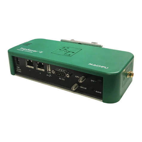
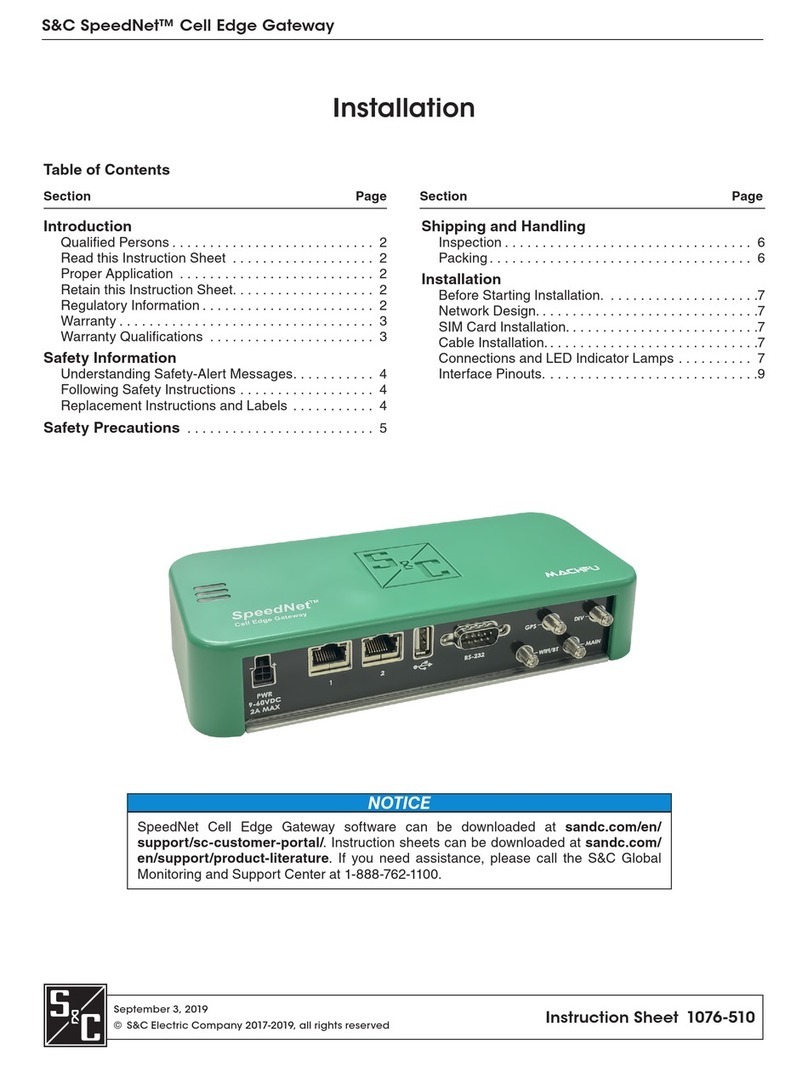
S&C SpeedNet User manual

September 3, 2019
© S&C Electric Company 2017-2019, all rights reserved Instruction Sheet 1076-530
SpeedNet™ Cell Edge Gateway
NOTICE
SpeedNet Cell Edge Gateway software and instruction sheets can be downloaded at
sandc.com/en/Support/Product-Literature/. If you need assistance, please contact
customerportal@sandc.com or call (800) 621-5546.
Setup
Table of Contents
Section Page Section Page
Introduction
Qualified Persons . . . . . . . . . . . . . . . . . . . . . . . . . . . 2
Read this Instruction Sheet . . . . . . . . . . . . . . . . . . . 2
Retain this Instruction Sheet. . . . . . . . . . . . . . . . . . . 2
Proper Application . . . . . . . . . . . . . . . . . . . . . . . . . . 2
Regulatory Information . . . . . . . . . . . . . . . . . . . . . . . 2
Warranty . . . . . . . . . . . . . . . . . . . . . . . . . . . . . . . . . . 4
Warranty Qualifications . . . . . . . . . . . . . . . . . . . . . . 4
Safety Information
Understanding Safety-Alert Messages. . . . . . . . . . . 5
Following Safety Instructions . . . . . . . . . . . . . . . . . . 5
Replacement Instructions and Labels . . . . . . . . . . . 5
Safety Precautions . . . . . . . . . . . . . . . . . . . . . . . . . 6
Shipping and Handling
Inspection . . . . . . . . . . . . . . . . . . . . . . . . . . . . . . . . . 7
Packing . . . . . . . . . . . . . . . . . . . . . . . . . . . . . . . . . . . 7
Access
Overview. . . . . . . . . . . . . . . . . . . . . . . . . . . . . . . . . . 8
System Requirements . . . . . . . . . . . . . . . . . . . . . . . 8
Login . . . . . . . . . . . . . . . . . . . . . . . . . . . . . . . . . . . . . 8
Navigation . . . . . . . . . . . . . . . . . . . . . . . . . . . . . . . . . 9
Dashboard . . . . . . . . . . . . . . . . . . . . . . . . . . . . . . . . 10
General Info Dashboard . . . . . . . . . . . . . . . . . . . . . .11
Cellular Dashboard. . . . . . . . . . . . . . . . . . . . . . . . . .12
Ethernet Dashboard . . . . . . . . . . . . . . . . . . . . . . . . .13
Wireless Interfaces . . . . . . . . . . . . . . . . . . . . . . . . 14
Cellular . . . . . . . . . . . . . . . . . . . . . . . . . . . . . . . . . . .15
Wired Interfaces . . . . . . . . . . . . . . . . . . . . . . . . . . . 16
Ethernet . . . . . . . . . . . . . . . . . . . . . . . . . . . . . . . . . .17
Serial Terminal Server . . . . . . . . . . . . . . . . . . . . . . .18
Network. . . . . . . . . . . . . . . . . . . . . . . . . . . . . . . . . . . 19
Bridge . . . . . . . . . . . . . . . . . . . . . . . . . . . . . . . . . . . 20
VPN. . . . . . . . . . . . . . . . . . . . . . . . . . . . . . . . . . . . . .21
Port Forwarding and Source NAT. . . . . . . . . . . . . . 24
Routes. . . . . . . . . . . . . . . . . . . . . . . . . . . . . . . . . . . 25
Settings. . . . . . . . . . . . . . . . . . . . . . . . . . . . . . . . . . . 26
Profile . . . . . . . . . . . . . . . . . . . . . . . . . . . . . . . . . . . 26
System . . . . . . . . . . . . . . . . . . . . . . . . . . . . . . . . . . . 27
System Upgrade . . . . . . . . . . . . . . . . . . . . . . . . . . . 27
General Settings. . . . . . . . . . . . . . . . . . . . . . . . . . . 28

2S&C Instruction Sheet 1076-530
Introduction
Qualified Persons WARNING
The equipment covered by this publication must be installed, operated, and
maintained by qualified persons who are knowledgeable in the installation,
operation, and maintenance of radios in electric power distribution equipment, along
with the associated hazards. A qualified person is a radio technician who is qualified
to install transmission-power-limited radio equipment per FCC Part 15 and who is
trained and competent in:
• The skills and techniques necessary to distinguish exposed live parts from nonlive
parts of electrical equipment
• The skills and techniques necessary to determine the proper approach distances
corresponding to the voltages to which the qualified person will be exposed
• The proper use of the special precautionary techniques, personal protective
equipment, insulating and shielding materials, and insulated tools for working on
or near exposed energized parts of electrical equipment
These instructions are intended only for such qualified persons. They are not
intended to be a substitute for adequate training and experience in safety procedures
for this type of equipment.
Read this
Instruction Sheet NOTICE
Thoroughly and carefully read this instruction sheet before programming, operating,
or maintaining your SpeedNet Cell Edge Gateway. Familiarize yourself with the
Safety Information and Safety Precautions on pages 5 and 6. The latest version
is available online in PDF format at sandc.com/en/Support/Product-Literature/.
Retain this
Instruction Sheet
This instruction sheet should be available for reference wherever a SpeedNet Cell Edge
Gateway is to be used. Retain this instruction sheet in a location where you can easily
retrieve and refer to it.
Proper Application WARNING
The equipment in this publication must be selected for a specific application. The
application must be within the ratings furnished for the selected equipment.
Regulatory
Information
FCC Statement
This equipment has been tested and found to comply with the limits for a Class A digital
device, pursuant to Part 15 of the FCC rules and regulations regarding unlicensed
radio-frequency transmissions. These limits are designed to provide reasonable
protection against harmful interference when the equipment is operated in a commercial
environment. This equipment generates, uses, and can radiate radio frequency energy and,
if not installed and used in accordance with the instruction manual, may cause harmful
interference to radio communications. Operation of this equipment in a residential area
is likely to cause harmful interference in which case the user will be required to correct
the interference at his own expense.

S&C Instruction Sheet 1076-530 3
Introduction
FCC Radiation Exposure Statement
This device complies with FCC radiation-exposure limits set forth for an uncontrolled
environment and it also complies with Part 15 of the FCC radio-frequency rules. This
equipment must be installed and operated in accordance with provided instructions,
and the antenna(s) used for this transmitter must be installed to provide a separation
distance of at least 20 cm (7.9 inches) from all persons and must not be co-located or
operating in conjunction with any other antenna or transmitter. End-users and installers
must be provided with antenna-installation instructions and consider removing the
no-collocation statement.
This device complies with Part 15 of the FCC radio-frequency rules. Operation is
subject to the following two conditions: (1) this device may not cause interference, and
(2) this device must accept any interference, including interference that may cause
undesired operation of the device.
Industry Canada Statement
This device complies with Industry Canada’s license-exempt RSSs. Operation is subject
to the following two conditions:
(1) This device may not cause interference; and (2) This device must accept any
interference, including interference that may cause undesired operation of the device.
Le present appareil est conforme aux CNR d’Industrie Canada applicables aux
appareils radio exempts de licence. L’exploitation est autorisée aux deux conditions
suivantes:
(1) l’appareil ne doit pas produire de brouillage; (2) l’utilisateur de l’appareil doit
accepter tout brouillage radioélectrique subi, même si le brouillage est susceptible d’en
compromettre le fonctionnement.
This transmitter must not be co-located or operating in conjunction with any other
antenna or transmitter. This equipment should be installed and operated with a mini-
mum distance of 20 centimeters (7.9 inches) between the radiator and your body.
Cet émetteur ne doit pas être Co-placé ou ne fonctionnant en même temps qu’aucune
autre antenne ou émetteur.
Cet équipement devrait être installé et actionné avec une distance minimum de 20
centimètres entre le radiateur et votre corps.
Industry Canada Radiation Exposure Statement
This device meets the exemption from the routine evaluation limits in section 2.5 of
RSS102 and users can obtain Canadian information on radio-frequency exposure and
compliance.
Le dispositif rencontre l’exemption des limites courantes d’évaluation dans la section
2.5 de RSS 102 et la conformité à l’exposition de RSS-102 rf, utilisateurs peut obtenir
l’information canadienne sur l’exposition et la conformité de rf.
NOTICE
Changes or modifications not expressly approved by S&C Electric Company could
void the user’s authority to operate the equipment.

4S&C Instruction Sheet 1076-530
Introduction
Warranty The warranty and/or obligations described in S&C’s Price Sheet 150 “Standard
Conditions of Sale–Immediate Purchasers in the United States” (or Price Sheet 153,
“Standard Conditions of Sale–Immediate Purchasers Outside the United States”), plus
any special warranty provisions, as set forth in the applicable product-line specication
bulletin, are exclusive. The remedies provided in the former for breach of these
warranties shall constitute the immediate purchaser’s or end user’s exclusive remedy
and a fulllment of the seller’s entire liability. In no event shall the seller’s liability to the
immediate purchaser or end user exceed the price of the specic product which gives
rise to the immediate purchaser’s or end user’s claim. All other warranties, whether
express or implied or arising by operation of law, course of dealing, usage of trade
or otherwise, are excluded. The only warranties are those stated in Price Sheet 150,
(or Price Sheet 153) and THERE ARE NO EXPRESS OR IMPLIED WARRANTIES OF
MERCHANTABILITY OR FITNESS FOR A PARTICULAR PURPOSE. ANY EXPRESS
WARRANTY OR OTHER OBLIGATION PROVIDED IN PRICE SHEET 150 (OR PRICE
SHEET 153) IS GRANTED ONLY TO THE IMMEDIATE PURCHASER AND END USER,
AS DEFINED THEREIN. OTHER THAN AN END USER, NO REMOTE PURCHASER
MAY RELY ON ANY AFFIRMATION OF FACT OR PROMISE THAT RELATES TO THE
GOODS DESCRIBED HEREIN, ANY DESCRIPTION THAT RELATES TO THE GOODS,
OR ANY REMEDIAL PROMISE INCLUDED IN PRICE SHEET 150 (or PRICE SHEET 153.)
Warranty
Qualifications
Warranty of the SpeedNet Cell Edge Gateway is contingent upon the installation,
conguration, and use of the SpeedNet Cell Edge Gateway and software in accordance
with S&C’s applicable instruction sheets. This warranty does not apply to major
components not of S&C manufacture, such as batteries, and other communication
devices not of S&C manufacture. However, S&C will assign to the immediate purchaser
or end user all manufacturers’ warranties that apply to such major components.

S&C Instruction Sheet 1076-530 5
Safety Information
Understanding
Safety-Alert Messages
Several types of safety-alert messages may appear throughout this instruction sheet
and on labels attached to the SpeedNet Cell Edge Gateway. Familiarize yourself with
these types of messages and the importance of these various signal words:
DANGER
“DANGER” identifies the most serious and immediate hazards that will likely
result in serious personal injury or death if instructions, including recommended
precautions, are not followed.
WARNING
“WARNING” identifies hazards or unsafe practices that can result in serious
personal injury or death if instructions, including recommended precautions, are
not followed.
CAUTION
“CAUTION” identifies hazards or unsafe practices that can result in minor personal
injury if instructions, including recommended precautions, are not followed.
NOTICE
“NOTICE” identifies important procedures or requirements that can result in
product or property damage if instructions are not followed.
Following Safety
Instructions
If you do not understand any portion of this instruction sheet and need assistance,
contact your nearest S&C Sales Ofce or S&C Authorized Distributor. Their telephone
numbers are listed on S&C’s website sandc.com, or call the S&C Global Support and
Monitoring Center at 1-888-456-1100.
NOTICE
Read this instruction sheet thoroughly
and carefully before installing or
operating your SpeedNet Cell Edge
Gateway.
Replacement
Instructions and
Labels
If additional copies of this instruction sheet are needed, contact your nearest S&C Sales
Ofce, S&C Authorized Distributor, S&C Headquarters, or S&C Electric Canada Ltd.
It is important that any missing, damaged, or faded labels on the equipment be
replaced immediately. Replacement labels are available by contacting your nearest
S&C Sales Office, S&C Authorized Distributor, S&C Headquarters, or S&C Electric
Canada Ltd.

6S&C Instruction Sheet 1076-530
Safety Precautions
DANGER
SpeedNet Cell Edge Gateways operate between 9 and 60 Vdc. Failure to observe
the precautions below will result in serious personal injury or death.
Some of these precautions may differ from your company’s operating procedures and
rules. Where a discrepancy exists, follow your company’s operating procedures and
rules.
1. QUALIFIED PERSONS. Access to an SpeedNet
Cell Edge Gateway must be restricted only to
qualified persons. See the “Qualified Persons”
section on page 2.
2. SAFETY PROCEDURES. Always follow safe
operating procedures and rules.
3. PERSONAL PROTECTIVE EQUIPMENT. Always
use suitable protective equipment such as rubber
gloves, rubber mats, hard hats, safety glasses, and
flash clothing, in accordance with safe operating
procedures and rules.
4. SAFETY LABELS. Do not remove or obscure any of
the “DANGER,” “WARNING,” “CAUTION,” or
“NOTICE” labels.
5. SAFE DISTANCE.
• Allpersonsshouldmaintainaminimumseparation
of 7.9 inches (201 mm) for the SpeedNet antenna.
• Disconnect the ac/dc input power source from the
SpeedNet Cell Edge Gateway whenever
configuring or repositioning the antenna.
6. MAINTAINING PROPER CLEARANCE. Always
maintain proper clearance from energized
components.

S&C Instruction Sheet 1076-530 7
Shipping and Handling
Examine the shipment for external evidence of damage as soon after receipt as possible,
preferably before removal from the carrier’s conveyance. Check the bill of lading to make
sure all listed shipping skids, crates, cartons, and containers are present.
If there is visible loss and/or damage:
1. Notify the delivering carrier immediately.
2. Ask for a carrier inspection.
3. Note condition of shipment on all copies of the delivery receipt.
4. File a claim with the carrier.
If concealed damaged is discovered:
1. Notify the delivering carrier within 15 days of receipt of shipment.
2. Ask for a carrier inspection.
3. File a claim with the carrier.
Also, notify S&C Electric Company in all instances of loss and/or damage.
A SpeedNet Cell Edge Gateway shipment includes the following items:
1. SpeedNet Cell Edge Gateway
2. Power cord
3. Antennas and other accessories, as applicable
Inspection
Packing

8S&C Instruction Sheet 1076-530
Access
The SpeedNet Gateway Conguration Tool is used to congure the SpeedNet Cell
Edge Gateway. This instruction sheet describes how the tool can be used to congure
and set various parameters in the SpeedNet Cell Edge Gateway for optimizing your
communication network and application.
The PC used to congure the gateway should meet the following requirements:
• Microsoft Windows 7/8/10
• Linux or Mac OS X
• Web browser that supports HTML5:
• Google Chrome or Microsoft Edge
NOTICE
For security purposes, web access to the gateway configuration interface is only
supported on LAN or VPN interfaces. If the ‘Firewall Group’ of Ethernet 1 is changed
to WAN from Default without first putting firewall rules in place, then it may lock out
the user preventing any web access to the gateway.
To access the gateway conguration interface, perform the following steps:
STEP 1. Connect a PC to the Ethernet 1 port.
STEP 2. Launch the Web browser.
STEP 3. Enter http://192.168.1.1 in the Address eld to connect to the gateway.
The Login screen appears. See Figure 1
Figure 1. The SpeedNet Cell Edge Gateway Login screen.
STEP 4. Fill in the Username and Password elds, and click on the Login button.
Overview
System Requirements
Login

S&C Instruction Sheet 1076-530 9
Navigation
The gateway conguration interface contains six main pages, seen in the navigation bar
on the left side of the interface. Each Web-based management page is used to congure
a specic aspect of the gateway. There are ve icons on the left panel: See Figure 2.
Dashboard is a synopsis of all the network configurations and the state elements of
the gateway. It displays device information, such as name and serial number, and the
current state of physical and virtual network interfaces.
Wireless displays wireless configuration elements and settings of the cellular radio.
Wired displays the operating mode of the two Ethernet interfaces and the Internet
Protocol (IP) settings.
Network displays the network services: Bridge, VPN, Routes, Port Forwarding, and
Source NAT.
Settings displays Password settings.
Figure 2: The Navigation panel.

10 S&C Instruction Sheet 1076-530
Dashboard
The dashboard is a synopsis of all the network congurations and the state elements of the
gateway. It provides a high-level view of the device and network interfaces. See Figure 3.
Figure 3. The Dashboard page.

S&C Instruction Sheet 1076-530 11
Dashboard
Figure 4. General Info section of the Dashboard screen.
Basic identifying information and high-level usage data that provide insight into the
gateway’s performance and capacity is shown in the “General Info” section of the
dashboard. This includes:
• DEVICE NAME – Indicates the device model name
• DEVICE SKU – Indicates the device SKU number
• SERIAL NUMBER – Set at manufacturing time and displayed here for reference
• RELEASE – Indicates the revision number of the device rmware
• SECURITY PATCH – Indicates the security patch level
• BUILD DATE – Indicates the build date of the device rmware
• UPTIME – Time elapsed since the last boot-up, shown in days, hours, minutes, and
seconds
• LOAD – CPU usage
• MEMORY – Memory currently used
• DISK/STORAGE – Storage available for applications
General Info
Dashboard

12 S&C Instruction Sheet 1076-530
Dashboard
Figure 5. The “Cell” section of the Dashboard screen.
Conguration and performance data for the cellular modem is shown in the “Cell” section
of the dashboard. See Figure 5. This information includes:
• STATUS – Either enabled or disabled
• PPP UP/DOWN – Indicates whether the cellular link is in an Up or Down state
• IP ADDRESS – The IP address of the PPP link
• NETWORK TYPE – The type of cellular network, such as LTE, 3G, CDMA, etc.
• SIGNAL STRENGTH – The received signal strength indicator (RSSI) on the cellular link
• BYTES TRANSMITTED – The number of bytes transmitted since boot-up
• BYTES RECEIVED – The number of bytes received since boot-up
Cellular Dashboard

S&C Instruction Sheet 1076-530 13
Dashboard
Two Ethernet interfaces are denoted by Ethernet1 and Ethernet2. They are identical in
terms of the user interface. See Figure 6.
Figure 6. Ethernet section of the Dashboard screen.
Conguration and performance data of each Ethernet interface is shown in the Ethernet
sections of the Dashboard. This information depicts:
• STATUS – Either enabled or disabled
• LINK UP/DOWN – Indicates whether the Ethernet link is in an Up or Down state
• LINK SPEED – The data rate on the Ethernet interface
• MAC ADDRESS – The MAC address of the Ethernet link
• IP ADDRESS – The IP address of the Ethernet link
• NETMASK – Subnet denition
• MODE – Has three possible options: Static IP, DHCP, or Bridge mode
• TX BYTES – The number of bytes transmitted since boot-up
• RX BYTES – The number of bytes received since boot-up
Ethernet Dashboard

14 S&C Instruction Sheet 1076-530
Wireless Interface
The wireless interface congurations are used to congure the cellular radio on the
gateway. See Figure 7. When clicking on the Wireless tab on the left panel, the user
interface appears.
Figure 7. The Wireless submenu in the Navigation panel.

S&C Instruction Sheet 1076-530 15
Wireless Interface
Figure 8. The Cellular Information screen.
Many informational items, such as the IMSI and ICCID of the SIM card, the manufacturer,
the model number of the cell modem, and others are noted in the “Information” section.
See Figure 8.
Under the Operator pull-down menu in the “Configuration” section, choose Verizon
or AT&T, depending on the carrier supported by the SIM. For the Rogers network in
Canada, choose AT&T.
Under APN in the “Configuration” section, enter the access point name to connect to
the cellular network, and click on the Submit button to apply the changes.
Cellular

16 S&C Instruction Sheet 1076-530
Wired Interfaces
The gateway has two Ethernet interfaces and can serve as a serial terminal server.
There are number of ways to configure these interfaces. The two Ethernet ports have
identical configuration elements. When clicking on the Wired tab on the left panel, the
user interface shows up. See Figure 9.
Figure 9. The Wired submenu in the Navigation panel.

S&C Instruction Sheet 1076-530 17
Wired Interfaces
The option is available to enable or disable an Ethernet interface even if the interface is
physically connected. To enable it, set the Enable Ethernet 1 or Enable Ethernet 2 setting
to the On position; to disable it, set it to the Off position. The two Ethernet ports have
identical conguration elements. See Figure 10.
Figure 10. The Ethernet 1 screen.
Conguration of the Ethernet 1 and Ethernet 2 interfaces are shown on their respective
pages:
• When selecting the mode, if the gateway has a static IP address, select the Static
IP option and enter the address in the IP Address box. If the gateway is assigned
dynamic addresses, then select the DHCP Client option; the IP Address box will be
automatically lled in this case. If the Ethernet interface is used to bridge data com-
ing over the interface to other communication means, select the Bridge option from
the mode choices.
• IP ADDRESS – This is the IP address of the Ethernet link, congured manually or
automatically, as described above.
NOTICE
When setting IP address for various interfaces (Ethernet, Wi-Fi, Bridge,
etc.), make sure they are all not set to the same address. For example, if one
interface is set to 192.168.1.1, then the address to other interfaces should be
set to something different, for example, 192.168.21.1. If identical IP addresses
are used, then it may lock out the user, preventing any Web access to the
gateway.
• Fill in the subnet denition in the Netmask box. If the gateway is assigned dynamic
addresses, then the Netmask box will be automatically lled.
• If the gateway is intended to serve as a DHCP server, set the Enable DHCP Server
setting to the On position.
• For the DHCP server, enter the DHCP range of values in the Starting DHCP Address
and Ending DHCP Address boxes.
• To allow the gateway to be pinged, set the Allow Ping setting to the On position.
• Click on the Submit button to apply the changes.
Ethernet

18 S&C Instruction Sheet 1076-530
Wired Interfaces
Figure 11 shows the elements to congure when using the serial port as a serial terminal
server.
Figure 11. The Serial Terminal Server screen.
Serial Terminal Server

S&C Instruction Sheet 1076-530 19
Network
The gateway has multiple network interfaces and different ways to congure these
interfaces. The congurations include the upstream WAN side as well as the downstream
LAN side. They include advanced functionalities such as VPN, bridging, and rewalls.
When clicking on the Network tab on the left panel, the user interface shows up. See
Figure 12.
Figure 12: The Network submenu of the Navigation panel.
Click on the item to be configured.

20 S&C Instruction Sheet 1076-530
Network
In Bridge mode, ports congured to participate in the bridge are all in the same Layer
2 (e.g. Ethernet) broadcast domain. This means all ports that are members of the bridge
are ports in a virtual Ethernet switch. Broadcast trafc, e.g. ARP, received on one port
will be relayed out to all other member ports. Unicast trafc received on one port will
be relayed per MAC address only to the correct output port (or to the gateway itself if
that is the destination address). Just as with an Ethernet switch, the bridge accumulates
knowledge of what MAC addresses are reachable on which ports in order to perform the
layer 2 switching function. See Figure 13.
Figure 13: Bridge Port Forwarding screen.
The Interfaces section displays all the interfaces currently bridged. Note that selecting
an interface for bridging is performed in the configuration of that interface as described
in the “Wired Interfaces” section on page 16.
NOTICE
When enabling Bridge mode, care must be taken to ensure Bridge mode is not
enabled on both LAN interfaces and especially on the LAN interface currently being
used for Web access to the gateway. Doing so can lock out the user, preventing any
Web access to the gateway.
In the Configuration section, the private IP address of the bridge can be set. Note that
here the IP address should be entered in the form <IP Address/Netmask>, for example,
192.168.2.1/24.
Click on the Submit button to apply the changes.
Bridge
Other manuals for SpeedNet
5
Table of contents
Other S&C Gateway manuals