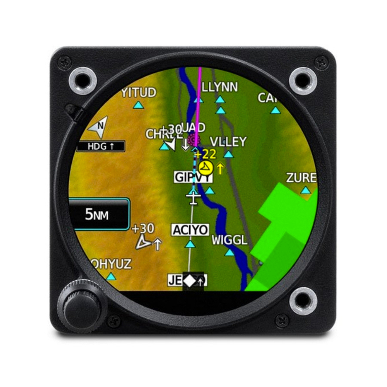
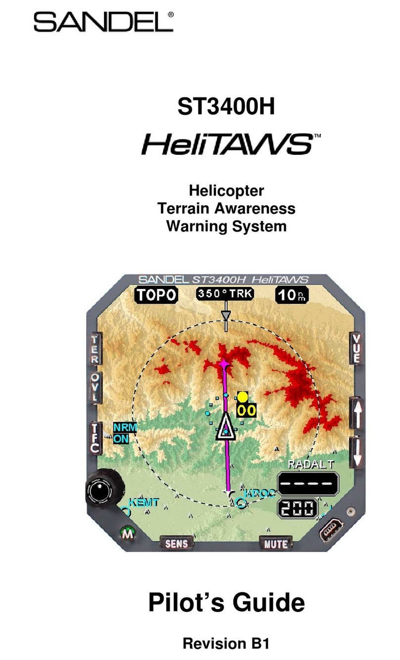
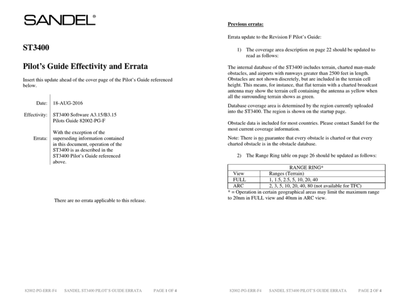
Sandel ST3400 User manual

ST3400 INSTALLATION MANUAL 82002-IM-L
1-2
Revision History
Rev Date Comments
L 08/18/2016
Incorporated AR2379
Section 1.4: Updated to include APN-194.
Section 9: List of effective drawings updated to reflect revision to sheet 7.
Section 10.2: Updated to include APN-194.
82002-10-3: Typo corrected.
82002-10-5: Typo corrected.
82002-10-7: Updated to include APN-194. Typos corrected.
K 02/06/14 Incorporated AR1356
Section 1: Approval page deleted.
Section 1.1.2 added for MOD-B units.
Section 3.8: Typo corrected.
Section 4.8: Typos corrected.
Section 8.4: Note added.
Section 9: List of effective drawings updated to reflect revisions to sheets 6
& 23.
Section 10.1: Updated for Garmin GTN-6XX/7XX equipment selections.
82002-10-3: Audio relay orientation corrected.
82002-10-5: Pin corrections. Notes updated.
82002-10-6: Updated to show additional grounds.
82002-10-7: Pin corrections.
82002-10-23: New drawing for Garmin GTN-6XX/7XX added.
J1 09/01/04 Incorporated A/R 740
Added error message list.
J 08/05/04 Incorporated A/R 717
Added information about Mod-A; Speaker Audio
Added Airdata AZ-648 Interface
H2 04/15/04 Incorporated A/R 697
Changed installation drawings list of effective pages for audio enable relay
H1 03/17/04 Incorporated A/R 690
Added Airdata AZ-600 Interface
H 02/18/04 Incorporated A/R 675
Removed #2 Radar Altimeter input
Removed #2 Analog Airdata input
Added FreeFlight 1201 WAAS GPS
Added Decision Height Input for Radar Altimeter
Added Altitude Callouts from radar altimeter
Added Back Course Input from HSI
Added CIC8800M & Penny & Giles D60286

Updated pin info on P3-8 selectable discrete out
Updated P1, P2, & P3 Pinouts
Updated Flap XYZ Input on Dwg 19
Added Flap, Glideslope Annunciators and Override Input
Added Traffic Interface
Updated King Air STC
G1 10/17/03
Incorporated A/R 661
Added GPS interface King KLN900.
Trimble 2000/3000/2101 and UPS GX Series
Added Airdata Collins ADC 80 Manchester Buss Interface,
Added Airdata Collins ADC85
Added Windshield Wiper Discrete Input
G 8/04/03
Incorporated A/R 638
Corrected Part Number of ST3400 Class B Gray
Added GPS interface Trimble 2101 I/O.
Added Airdata IS&S ADDU
Added separate TCAS Inhibit Output
Added Configuration Module Description
F 4/15/03
Incorporated A/R 626
Note about C92 GPWS systems
HDG added to Req’d equip list.
Note added in GEAR section about fixed-gear aircraft
Note on flaps in ‘takeoff’ configuration
Added GPS interface King KLN94
Added Airdata Collins ADC82 (), Honeywell AM-250 & AZ-810
Added OAT RS232 Interface
Added Flap XYZ Interface
Corrected missing ‘x’ in class-A configuration chart
Note about discrete inputs in signal characteristics table
Corrected various typographical errors
82002-IM-L ST3400 INSTALLATION MANUAL
1-3

E 02/21/03
Incorporated A/R-610 – Software version 2.00
Added sensor configuration charts and Airdata chart
Added reference to ST3400 Component Maintenance Manual
Added GPS interface II Morrow 2001, 2101 and Universal UNS-1X
Added Garmin 4XX & 5XX RS232 interface.
Added Bendix/King KRA405 & KRA405B, and Sperry RT220 & RT300.
Added Collins ADF-462 & ADF60A/B and Bendix/King KR-87.
Added Nav Rx’s Bendix/King KX155/165,
Collins VIR30/31, VIR432 and Garmin 430/530.
Added Airdata Honeywell AZ-252.
Removed references to negative climb rate after takeoff.
Revised notes on 1.05 actually apply to 2.00
D(2) 10/24/02
Incorporated A/R-578
Added ADC-80 Interface Removed incorrect callouts on P2
D(1)
10/02/02
Incorporated A/R-572
4.9 Added Signal Characteristics Table
4.5 – 4.7 Reformatted pin tables
Added signal characteristics to pin tables
D
09/25/02
Incorporated A/R 564
Flaps changed to required input.
RA1 FAIL and RA2 FAIL added
Windshield Wiper shared with RA2 FAIL
Note on configuration module
Added Gamin 165 GPS Interface
Added Penny & Giles Airdata
C
06/18/02
A/R 547:
Software 1.04/1.05 Notes; OAT; GPS Altitude
B1
05/29/02
Incorporated A/R 525
TOC: Corrected Radar Altimeter Error
1.2.6 Removed GPS Altitude
B
05/21/02
Incorporated A/R 525
Added reference to Patents
1.2.2 Updated Class B Air Data Requirements
3.4 Removed Alert Test
3.13 Removed reference to GPS Altitude
6.3.8 Removed reference to software 1.10
Dwg Page 1, Updated Block Diagram
Dwg Page 2, Updated Block Diagram
Dwg Page 10, Updated Air Data
A
04/12/02
Initial Release
ST3400 INSTALLATION MANUAL 82002-IM-L
1-4

TABLE OF CONTENTS
1GENERAL INFORMATION......................................................................1-10
1.1 Introduction......................................................................................................1-10
1.1.1 MOD-A Status...........................................................................................1-10
1.1.2 MOD-B Status ...........................................................................................1-10
1.2 Descriptions ......................................................................................................1-10
1.2.1 ST3400 TAWS/RMI Description ..............................................................1-10
1.2.2 TAWS Description.....................................................................................1-11
1.2.3 TAWS Class A/Class B Required Equipment...........................................1-12
1.2.4 FAA TAWS Requirement by Type of Operation......................................1-13
1.2.5 RMI Description ........................................................................................1-13
1.2.6 Terrain Database........................................................................................1-13
1.2.7 Coverage area of the databases..................................................................1-14
1.2.8 Keeping the databases current ...................................................................1-14
1.3 Technical Specifications ..................................................................................1-14
1.3.1 Approval Data............................................................................................1-14
1.3.2 Physical Dimensions..................................................................................1-15
1.3.3 Operational Characteristics........................................................................1-15
1.4 Interface Characteristics.................................................................................1-16
1.5 Part Numbers...................................................................................................1-17
1.5.1 ST3400 Part Number .................................................................................1-17
1.5.2 Installation Kit Part Number......................................................................1-17
1.6 License Requirements......................................................................................1-17
1.7 Technical Standard Order Stipulation..........................................................1-18
1.8 Installation and Operational Approval Procedures.....................................1-18
2INSTALLATION PLANNING .....................................................................2-1
2.1 General Information..........................................................................................2-1
2.2 Allowed Sensor Configuration Matrix – Class A............................................2-1
2.2.1 Required Sensors (Class-A).........................................................................2-1
2.2.2 Additional Required Sensors, allowed configurations (Class-A)................2-1
2.3 Allowed Sensor Configuration Matrix – Class B............................................2-1
2.3.1 Required Sensors (Class-B).........................................................................2-1
2.3.2 Additional Required Sensors, allowed configurations (Class-B) ................2-2
2.3.3 Optional Capabilities for Class-B, needed Sensors .....................................2-2
82002-IM-L ST3400 INSTALLATION MANUAL
1-5

2.4 Altitude Sources and Airdata ...........................................................................2-2
2.4.1 Airdata System Block Diagram ...................................................................2-3
2.4.2 OAT Requirements......................................................................................2-4
2.5 Pre-installation Planning...................................................................................2-4
2.6 Post Installation Procedures .............................................................................2-5
3INTERFACE FUNCTIONS.........................................................................3-1
3.1 Dual Inputs.........................................................................................................3-1
3.2 Power...................................................................................................................3-1
3.3 External Annunciators......................................................................................3-1
3.4 Flaps ....................................................................................................................3-2
3.5 Landing Gear .....................................................................................................3-2
3.6 Autopilot .............................................................................................................3-2
3.7 Audio Panel.........................................................................................................3-3
3.8 GPS/FMS............................................................................................................3-3
3.9 Radar Altimeter.................................................................................................3-3
3.10 Heading System..................................................................................................3-4
3.11 ADF Receiver .....................................................................................................3-4
3.12 NAV Receiver and Glideslope...........................................................................3-5
3.13 Air Data Computer............................................................................................3-5
3.14 OAT Probe..........................................................................................................3-5
3.15 Traffic..................................................................................................................3-6
3.16 ST3400 Interlink ................................................................................................3-6
3.17 Uploading Equipment........................................................................................3-6
3.18 Display Dimming................................................................................................3-6
3.19 Windshield Wipers.............................................................................................3-6
4INSTALLATION......................................................................................... 4-1
4.1 Unpacking and Inspecting Equipment ............................................................4-1
ST3400 INSTALLATION MANUAL 82002-IM-L
1-6

4.2 Cooling Considerations .....................................................................................4-1
4.3 Mechanical Installation Considerations ..........................................................4-1
4.3.1 Instrument Location in the Cockpit .............................................................4-1
4.3.2 Assembly and Mounting Instructions..........................................................4-1
4.4 Electrical Installation Considerations..............................................................4-2
4.5 Connector P1......................................................................................................4-3
4.5.1 View of Mating Connector to P1.................................................................4-5
4.6 Connector P2......................................................................................................4-6
4.6.1 View of Mating Connector to P2.................................................................4-8
4.7 P3 Connector......................................................................................................4-9
4.7.1 View of Mating Connector to P3.................................................................4-9
4.8 P4 Connector....................................................................................................4-10
4.9 Signal Type Electrical Characteristics...........................................................4-11
5MAINTENANCE MODE.............................................................................5-1
5.1 Normal Mode Operation...................................................................................5-1
5.2 Maintenance Mode.............................................................................................5-1
6SETUP PROCEDURES.............................................................................6-1
6.1 General................................................................................................................6-1
6.1.1 Accessing Maintenance Pages.....................................................................6-1
6.1.2 Uploading Data or System Software............................................................6-1
6.1.3 Configuration Module..................................................................................6-1
6.1.4 Configuration Module Status Page..............................................................6-2
6.1.5 Tail Number.................................................................................................6-2
6.2 Maintenance Index Page ...................................................................................6-3
6.2.1 Maintenance Page Number/Title .................................................................6-3
6.2.2 Cursor...........................................................................................................6-3
6.2.3 Soft Keys......................................................................................................6-4
6.2.4 Edit/Read Mode Indicator............................................................................6-5
6.2.5 How to Access Maintenance Pages .............................................................6-5
6.3 Maintenance Pages.............................................................................................6-6
6.3.1 System Maintenance Page ...........................................................................6-6
6.3.2 Air Data Page...............................................................................................6-7
6.3.3 ADF & HDG Page.......................................................................................6-8
6.3.4 Discretes Maintenance Page ........................................................................6-9
6.3.5 NAV and ILS Page ....................................................................................6-10
6.3.6 RADALT Maintenance Page.....................................................................6-11
82002-IM-L ST3400 INSTALLATION MANUAL
1-7

6.3.7 GPS/FMS...................................................................................................6-12
6.3.8 TCAS .........................................................................................................6-13
6.3.9 Status Page.................................................................................................6-14
6.3.10 Callouts......................................................................................................6-15
7POST INSTALLATION............................................................................ 7-16
7.1 General..............................................................................................................7-16
7.1.1 Accessing Maintenance Pages...................................................................7-16
7.2 Post Installation Testing..................................................................................7-17
7.2.1 Power-On Self-Test ...................................................................................7-17
7.2.2 ST3400 TAWS/RMI..................................................................................7-17
7.2.3 Install Sandel ST3400 TAWS/RMI into aircraft.......................................7-17
7.2.4 Record the following Aircraft Configuration ............................................7-17
7.2.5 Record the following system information: ................................................7-17
7.2.6 Required Test Equipment: .........................................................................7-17
7.2.7 Brightness/Audio Page...............................................................................7-18
7.2.8 Alerts Test..................................................................................................7-18
7.2.9 Power Maintenance Page...........................................................................7-19
7.2.10 Software CRC Page ...................................................................................7-20
7.2.11 ST3400 CONFIGURATION.....................................................................7-20
7.2.12 AIR DATA INPUT TESTS.......................................................................7-23
7.2.13 ADF INPUT TESTS..................................................................................7-24
7.2.14 HEADING INPUT TESTS........................................................................7-24
7.2.15 DISCRETE INPUTS TESTS.....................................................................7-25
7.2.16 NAV& ILS INPUT TESTS.......................................................................7-25
7.2.17 RADAR ALTIMETER..............................................................................7-26
7.2.18 GPS/FMS 1................................................................................................7-27
7.2.19 GPS/FMS 2................................................................................................7-28
7.2.20 TRAFFIC ...................................................................................................7-28
7.2.21 Activate the TAWS Inhibit........................................................................7-28
7.2.22 Power up the GPS/FMS.............................................................................7-28
7.2.23 Initialize GPS/FMS....................................................................................7-29
7.2.24 Fail the GPS/FMS......................................................................................7-29
7.2.25 Run TAWS self-test...................................................................................7-29
7.2.26 Verify the ST3400 display.........................................................................7-29
7.2.27 Verify the ST3400 manual display............................................................7-29
7.2.28 Verify the ST3400 visibility and accessibility...........................................7-30
8INSTRUCTIONS FOR CONTINUED AIRWORTHINESS..........................8-1
8.1 General................................................................................................................8-1
8.2 Databases............................................................................................................8-1
8.3 Lamp Replacement............................................................................................8-1
8.4 Software Updates...............................................................................................8-1
ST3400 INSTALLATION MANUAL 82002-IM-L
1-8
9INSTALLATION DRAWINGS....................................................................9-1
10 APPENDIX A: EQUIPMENT AND INTERFACES ..................................10-1
10.1 GPS/FMS..........................................................................................................10-1
10.1.1 ARINC 429 LABELS for GPS/FMS.........................................................10-2
10.2 RADAR ALTIMETER....................................................................................10-2
10.2.1 ARINC 429 LABELS for Radar Altimeter ...............................................10-3
10.3 HEADING ........................................................................................................10-3
10.3.1 ARINC 429 LABELS for Heading............................................................10-3
10.4 ADF ...................................................................................................................10-3
10.4.1 ARINC 429 LABELS for ADF .................................................................10-3
10.5 NAV...................................................................................................................10-3
10.5.1 ARINC 429 LABELS for NAV.................................................................10-3
10.6 AIRDATA.........................................................................................................10-4
10.6.1 ARINC 429 LABELS for Airdata .............................................................10-4
10.7 TRAFFIC..........................................................................................................10-4
11 APPENDIX B: ENVIRONMENTAL QUALIFICATION FORM.................11-1
12 APPENDIX C: STC.................................................................................12-1
12.1 STC Permission................................................................................................12-1
12.2 STC: Cessna 421C Series ...............................................................................12-2
12.3 STC: King Air C90, 200, 300 and B300 Series.............................................12-3
82002-IM-L ST3400 INSTALLATION MANUAL
1-9

1 GENERAL INFORMATION
1.1 Introduction
The information contained within this Installation Manual describes the features,
functions, technical characteristics, components, approval procedures, installation
considerations, setup procedures, checkout procedures and instructions for
continued airworthiness for the Sandel Avionics ST3400 TAWS/RMI.
Sandel Avionics ST3400 TAWS/RMI may be covered by one or more U.S. and
foreign patents and pending patent applications, including U.S. Patent Nos.
6,507,288, 6,489,916, and 6,259,378.
1.1.1 MOD-A Status
Certain enhancements exist on units marked as “MOD-A” on the dataplate.
These enhancements cannot be retrofitted to to non MOD-A units.
1. The display has higher resolution
2. 2nd audio output available which can drive 8 ohm speaker directly
3. Availability of auto dimming of the display from the Pilot’s Menu.
4. Cooling Fan will cycle off below approximately 0° C
5. Self-test will operate all annunciator outputs.
6. Capability of interfacing to CIC brand analog airdata Computers
Mod-A status can be determined from the data plate, or from the Pilot’s Menu
where the Mod-A status is shown in the upper right of the screen.
NOTE: See section on software loading for other information about MOD-A.
1.1.2 MOD-B Status
MOD-B units contain the same enhancements as MOD-A units and have even
higher display resolution.
Mod-B status can be determined from the TSO label, or from the Pilot’s Menu
where the Mod-B status is shown in the upper right of the screen.
NOTE: See section on software loading for other information about MOD-B.
1.2 Descriptions
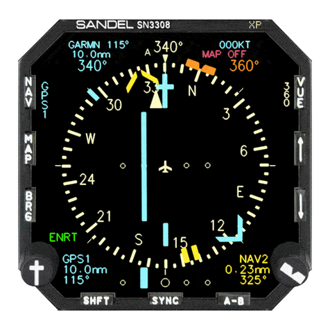
1.2.1 ST3400 TAWS/RMI Description
The Sandel ST3400 is a self-contained TAWS (Terrain Awareness Warning
System) solution that includes a TAWS computer and an integrated full-color
screen, built within a standard 3-inch instrument chassis.
It can be used as a direct replacement for a currently installed RMI (Radio
Magnetic Indicator).
ST3400 INSTALLATION MANUAL 82002-IM-L
1-10

The ST3400 uses Sandel’s patented rear-projection display technology. The
projector uses a miniature active-matrix LCD display that produces a high-
resolution image that is rear-projected directly to the face of the instrument. This
technology allows the displayed image to extend to the edges of the instrument’s
bezel. The advantage of this edge-to-edge technology is that it eliminates the
unusable area surrounding conventional LCD and CRT displays. Even though the
Sandel display is in a 3-inch form factor, its image is near the size of a 4” primary
display, and it remains directly in the pilot’s field-of-view.
The ST3400 includes built-in warning and caution annunciation. The unit also
supports optional external warning or caution annunciation.
The ST3400 may be installed in a pilot-only or dual pilot/copilot configuration.
The ST3400 has an internal recorder that automatically records ten hours of flight
data. This data can be reviewed for content in the event of a system malfunction.
1.2.2 TAWS Description
TAWS is the enhanced terrain warning technology that replaces the older GPWS
(Ground Proximity Warning System) technology. It is also known as EGPWS
(Enhanced GPWS).
TAWS adds two new and critical capabilities, FLTA (Forward Looking Terrain
Avoidance) and PDA (Premature Decent Alert) to the standard GPWS functions.
The six standard GPWS functional modes are:
•ERD (excessive rate of descent)
•ECRT (excessive closure rate to terrain)
•ALAT (altitude loss after takeoff)
•FITNL (flight into terrain when not in landing configuration)
•EDGSD (excessive downward glide slope deviation).
•500’ Voice Callout
The ST3400 can be configured either as a Class A TAWS compliant system or as
a Class B TAWS compliant system depending on the availability of radar
altimeter and airdata.
When configured as a Class B TAWS system, the ST3400 exceeds Class B
TAWS requirements. Even in Class B mode without radar altimeter, the ST3400
has additional Class A features such as a display and an excessive glide slope
deviation alert. See the POH for additional information
CLASS A TAWS FUNCTIONAL REQUIREMENTS
Mode
Function
FLTA
Forward Looking Terrain Alert
PDA
Premature Descent Alert
GPWS Mode 1
Excessive Rate of Descent
82002-IM-L ST3400 INSTALLATION MANUAL
1-11

GPWS Mode 2
Excessive Closure Rate to Terrain
GPWS Mode 3
Altitude Loss After Takeoff
GPWS Mode 4
Flight Into Terrain Not in Landing Configuration
GPWS Mode 5
Excessive Downward Deviation from Glideslope
GPWS Mode 6 Voice callout “Five Hundred” when the aircraft descends through
500 feet Radar Altitude
Class A TAWS requires a display, which shows the aircraft in relation to the terrain. Satisfied
by the ST3400 dedicated display.
Class A TAWS requires a radar altimeter (for GPWS functions).
CLASS B TAWS FUNCTIONAL REQUIREMENTS
Mode
Function
FLTA
Forward Looking Terrain Alert
PDA
Premature Descent Alert
GPWS Mode 1
Excessive Rate of Descent
GPWS Mode 3
Altitude Loss After Takeoff
GPWS Mode 6 Voice callout “Five Hundred” when the aircraft descends to 500
feet above the nearest runway elevation
When configured as a Class B TAWS system, the ST3400 exceeds the FAA Class B TAWS requirements.
Even in Class B mode without radar altimeter, the ST3400 includes Class A features such as a terrain
display and an excessive glide slope deviation alert, when so configured.
1.2.3 TAWS Class A/Class B Required Equipment
The ST3400 uses the following equipment to meet Class A or Class B
requirements.
ST3400 CLASS A TAWS EQUIPMENT REQUIREMENTS
Equipment
Class A
Class B
Terrain Display
Integrated
Integrated
Radar Altimeter
Required
Optional
GPS or FMS System
Required
Required
Heading System
Required
Required
Audio Panel
Required
Required
Air Data Computer
Required
Dependent on GPS
Remote
Switch/Annunciators
Optional in single pilot aircraft;
required in two-crew aircraft
Optional
Flap Position
Required
Recommended
Gear Position
Required if retract gear
Recommended
ILS Receiver
Required
Recommended
NAV
Optional (for RMI)
Optional (for RMI)
ST3400 INSTALLATION MANUAL 82002-IM-L
1-12

ADF
Optional (for RMI)
Optional (for RMI)
OAT Probe
Required for Corrected Baro Alt
1.2.4 FAA TAWS Requirement by Type of Operation
The FAA has mandated that all U.S.-registered turbine powered aircraft that have
six or more passenger seats be equipped with a TAWS no later than March 5,
2005.
Depending on the number of seats and the type of operation, the TAWS
requirement will be for a Class A system or a Class B system.
FAA TAWS REQUIREMENT BY TYPE OF OPERATION
Class
Type of Operation
Number of Passenger Seats
Class A
FAR Part-121
ALL
Class A
FAR Part-135
10 or more
Class B
FAR Part-135
6-9
Class B
FAR Part-91
6 or more
1.2.5 RMI Description
The ST3400 RMI function is provided to allow the ST3400 to replace an existing
installed electromechanical RMI. The Sandel RMI displays aircraft heading
information on a calibrated compass card read against a fixed lubber line.
Bearing is provided to both a primary pointer and a secondary pointer, each of
which is read against the compass card.
Each pointer may be switched independently to any installed navigation source,
which may be a VOR, ADF, or the GPS/FMS waypoint. The ability to assign the
GPS/FMS to a bearing pointer is unique to the ST3400 RMI.
If the navigation source has an invalid state available, the associated bearing
pointer will be removed completely from the display instead of being parked at
90° as is common in mechanical RMI’s. Each pointer may be independently
turned on or off and independently selected to the aircraft navigation sources.
1.2.6 Terrain Database
The ST3400 provides predictive “look ahead” warnings by comparing it’s internal
terrain database to positioning information provided by the GPS, INS, or FMS
system. The terrain database includes obstacles. For a Class A installation,
additional information is received from a radar altimeter. Altitude information is
received from GPS or airdata computer.
82002-IM-L ST3400 INSTALLATION MANUAL
1-13

1.2.7 Coverage area of the databases
The internal databases of the ST3400 contain terrain including charted man-made
obstacles, and airports with runways greater than 2500 feet in length or as
indicated in the airport database notes. Obstacles are not shown discretely, but are
included in the terrain cells. This means, for instance, that flat terrain with a
charted broadcast antenna may show the terrain cell containing the antenna as
Yellow when all the surrounding terrain shows as Green.
The Terrain and Airport databases are provided by geographical area. The
coverage area of the database installed in the ST3400 is shown as part of the sign-
on screen after a power cycle.
Obstacle data from North America and Europe is currently incorporated in the
respective terrain databases. Additional obstacle data will be included as more
obstacles become charted and information becomes available.
Remember, there is no guarantee that every obstacle is charted or that every
charted obstacle is in the terrain data.
1.2.8 Keeping the databases current
Updates to the coverage area databases can be obtained on CD ROM from Sandel
or downloaded from the Sandel web site into a Windows loader program on a
laptop computer. The terrain data and/or airport data is then downloaded from the
PC into the ST3400 through a high-speed USB port located on the front right
corner. Loading instructions are supplied along with the applicable database.
The databases can be updated during normal maintenance to the aircraft.
Note: since USB is not supported in Windows-95, only Windows-98 (and later)
Microsoft operating systems are supported.
1.3 Technical Specifications
The following section describes the technical characteristics, which include the
appliance approval basis, physical and electrical properties, electrical connector
pin allocation which details function and gradient or equipment protocol, and
ARINC label support. Also included is the description of the ST3400 installation
components, other equipment and installation requirements. A review of the
installation approval procedures is provided for filing with authorities.
1.3.1 Approval Data
Technical Standard Order:
TSO
-151b (Class A/Class B) *
TSO-C113
Software Certification:
DO-178B
Environmental:
DO-160D
Databases:
DO
-200A
ST3400 INSTALLATION MANUAL 82002-IM-L
1-14

*Note: C151b is inclusive of TSO C92 and the ST3400 may be used to
replace/upgrade C92 Ground Proximity Warning Systems
1.3.2 Physical Dimensions
The ST3400 is enclosed in an ARINC 408, 3ATI form factor enclosure and is
mounted to an instrument panel.
Form Factor:
3ATI (ARINC 408)
Width:
3.175 inches
Height:
3.175 inches
Length:
9.5 inches
Weight:
3.2 pounds with connectors and configuration module.
(Cable weight not included)
Mounting:
Clamp
Display:
1 mega-pixel, 256 color (144,000 color triad)
1.3.3 Operational Characteristics
Temperature/Altitude:
-20° C to +70° C / up to 55,000 F
Power Input: 28VDC nominal, 40 watt maximum. Operating range
22VDC – 33VDC
Cooling Requirements: Internal fan. Requires ambient air at fan input along
the four corners of the 3ATI case.
82002-IM-L ST3400 INSTALLATION MANUAL
1-15

1.4 Interface Characteristics
Sandel pioneered smart interface technology makes the ST3400 compatible with
all vintages of digital and analog aircraft systems.
The ST3400 is software configurable and configuration data is stored internally
and in an optional airframe-resident configuration module (active in software 2.10
and later). No hard-wired jumpers are used.
Configuration Module Rear mounted configuration module inside 9-pin ‘D’
connector shell (optional)
Data Loading 12Mbs USB Port using Microsoft Windows compatible
computer. Windows 98 and later required.
GPS/FMS
ARINC 429 or RS232
Air Data
ARINC 429 or Analog
Heading
ARINC 429 or XYZ (ARINC 407)
Gear ARINC 429 Label 270 or Discrete active high or low.
Active State = Gear Down
Flap ARINC 429 Label 270 or Discrete active high or low.
Active State = Flaps in Landing Configuration
Autopilot Engage ARINC 429 or Discrete active high or low.
Active State = Autopilot Engaged
RMI ADF: ARINC 429 or DC Sin/Cos or Arinc 407 XYZ
VOR: ARINC 429 or Composite Video
Glideslope
ARINC 429 or low-level deviation and flag
Localizer
ARINC 429 or Composite Analog ILS (ARINC 710)
NAV
ARINC 429 or Composite Analog VOR (ARINC 711)
Alert Audio (LL)
600 ohm unbalanced + 14 dbm maximum
Alert Audio (Spkr)
8 ohm, 4 watt max
External Annun
Lamps Ground = Active, 250ma maximum (optional)
Radar Altimeter ARINC 429 or 0-2000 ft or 0 – 2,500 ft in ARINC 565,
Alt-50, Alt-55 analog format, Sperry RT220/300 analog
format, 0-2500 ft at –4mV per Ft. APN-194 analog
format.
TRAFFIC
ARINC 429
ST3400 INSTALLATION MANUAL 82002-IM-L
1-16

1.5 Part Numbers
1.5.1 ST3400 Part Number
Part number ST3400-00x is the standard version of the ST3400. The –dash
number indicates product variations
-0xx Certified for Class A or B installations
-1xx Certified for Class B installation only
”Minor variations” are reserved for future product enhancements or special
applications.
Model Minor
Variation
ST3400-0xx
Class
ST3400-000, CLASS A BLACK
ST3400-001, CLASS A GRAY
ST3400-100, CLASS B BLACK
ST3400-102, CLASS B GRAY
1.5.2 Installation Kit Part Number
An installation kit is available for the ST3400.
ST3400 INSTALLATION KIT (P/N 90130-IK)
Qty
Sandel P/N
Positronics P/N
Description
J1 1 32063 DD44F10JVLO Connector 44 pin
Plastic Hood/Slide Lock and Contacts
J2 1 32063 DD44F10JVLO Connector 44 pin
Plastic Hood/Slide Lock and Contacts
J3 1 32062 SD15F10JVLO Connector 15 pin
Plastic Hood/Slide Lock and Contacts
1.6 License Requirements
None.
82002-IM-L ST3400 INSTALLATION MANUAL
1-17

1.7 Technical Standard Order Stipulation
The following stipulation as presented is required by the federal Aviation
Administration for articles approved under Technical Standard Order. This
statement does not preclude multiple installation and operational approvals in
regard to specific aircraft make, model, or type:
The conditions and tests required for TSO approval of this
article are minimum performance standards. It is the
responsibility of those installing this article either on or within
a specific type or class of aircraft to determine that the aircraft
installation conditions are within the TSO standards. TSO
articles must have separate approval for installation in an
aircraft. The article may be installed only in compliance with
14 CFR Part 43 or the applicable airworthiness requirements.
1.8 Installation and Operational Approval Procedures
The Environmental Qualification Form for the ST3400 is included as an
Appendix within this Installation Manual. It should be referenced to the
categories appropriate to the aircraft type and environment into which the ST3400
is to be installed. The environmental category for the ST3400 should be
stipulated on the STC form.
A “Functional Ground Test Procedures/Report” and an “Operational Flight Check
Procedures Report” are included in an Appendix to this manual. They should be
used as a basis for validating the ST3400 equipment configuration and to verify
proper installation and functional performance. A permanent copy of the STC
form must be filed and maintained by the installing agency. Another copy must
be presented to the aircraft owner for entry into the aircraft maintenance records,
as well as a copy forwarded to Sandel Avionics along with the Warranty
Registration Form, to be filed after completion and installation acceptance.
If any difficulty is experienced with the functionality or operational performance
of the ST3400, contact Sandel for assistance.
ST3400 INSTALLATION MANUAL 82002-IM-L
1-18

2 INSTALLATION PLANNING
The ST3400 has been designed to ensure maximum interoperability with all types
avionics. Contact Sandel with any questions about interfacing to specific avionics
equipment not covered in the installation drawings in this manual.
2.1 General Information
To simplify installation, after signals are wired to the ST3400 pins, on-screen
setups are used in a post-installation procedure. Maintenance menu pages provide
a function selection capability. For most FMS systems, selections are made by
equipment make and model.
Refer to the installation schematics in an Appendix of this manual for details on
connecting required components.
2.2 Allowed Sensor Configuration Matrix – Class A
2.2.1 Required Sensors (Class-A)
1. Heading
2. GPS position
3. Localizer and Glideslope
4. Radar Altitude
5. Baro Rate (Vertical Speed)
6. Flaps
7. Gear (only if the aircraft has retractable gear).
2.2.2 Additional Required Sensors, allowed configurations (Class-A)
Config GPS Alt Corr. Baro Alt Press. Alt OAT
1
x
x
x
2
x
x
3
x
x
(Item shown blank not required)
Contact factory for configurations other than those listed.
2.3 Allowed Sensor Configuration Matrix – Class B
2.3.1 Required Sensors (Class-B)
1. Heading
2. GPS position
82002-IM-L ST3400 INSTALLATION MANUAL
2-1

2.3.2 Additional Required Sensors, allowed configurations (Class-B)
Config
GPS Alt
Corr. Baro Alt
Baro Rate (VS)
OAT
1
x
2
x
x
x
(item shown blank not required)
Contact factory for configurations other than those listed.
2.3.3 Optional Capabilities for Class-B, needed Sensors
The following chart will assist in installation planning to add capabilities in
exceedence of Class-B requirements. Without these capabilities GPWS modes 2,
4 and 5 are inoperative. With all the capabilities enabled full Class-A
performance is provided, which provides autonomous GPWS protection if the
GPS/FMS should fail.
Capability Desired
Sensors Needed
GPWS Mode-2 ECRT
Radar Altitude; Baro Rate (VS); Flaps; Gear
2
Optional
GPWS Mode-4 FITNL
Radar Altitude, Baro Rate (VS); Flaps; Gear
2
GPWS Mode-5 Glideslope
1
Localizer; Glideslope; Gear
2
and/or Flaps
1Sandel recommended. 2Req’d only on retractable-gear aircraft
2.4 Altitude Sources and Airdata
Airdata hookup is one of the more complex installation planning issues since
there are many variations in types of airdata systems. This is particularly true of
aircraft upgraded for RVSM, where the altitude source may be a new digital
altimeter but the VS source may be the original airdata computer, which has been
left in the aircraft to interface with other existing systems. In order to make a
flexible system that requires as little additional equipment as possible, the ST3400
supports separate selection of sources for Altitude, Vertical Speed, and OAT.
Please pay careful attention this fact when planning installation. See section
2.4.1 Airdata System Block Diagram.
ST3400 software 1.05 and earlier requires Corrected Barometric Altitude for
either Class-A or Class-B installations. ST3400 software 2.00 and later supports
GPS altitude or Corrected Barometric Altitude, or both. If both are supplied CBA
is used as a backup to GPS altitude if available. See the installation diagrams for
a list of approved receivers which can supply GPS altitude to the ST3400
For Class-A, at a minimum Barometric Vertical Speed and Barometric Altitude
(either corrected or uncorrected) is required. This is used for the classic GPWS
portion of the alerting system, such as mode-1 “Excessive Descent Rate” etc.
For Class-B, if GPS altitude is used, no other source of altitude is required; i.e.
airdata is not required.
ST3400 INSTALLATION MANUAL 82002-IM-L
2-2
Other manuals for ST3400
1
Table of contents
Other Sandel Avionic Display manuals
Popular Avionic Display manuals by other brands

Aeroplans Blaus
Aeroplans Blaus ART-27C user manual

AEM
AEM AA21-400 Maintenance manual

Garmin
Garmin Approach G5 - GPS-Enabled Golf Handheld Maintenance manual

air avionics
air avionics AIR Control Display 57 Pilot's manual

Garmin
Garmin CIRRUS PERSPECTIVE SR2x pilot's guide

Flybox
Flybox Omnia57 Series Installation and user manual