Sanden SD7H15 User manual

Sanden SD7H15 Type C Service Manual
Date of Issue: July 1999
Prepared by: Sanden International (Europe) Ltd.
SANDEN

SD7H15 Type C Service Manual
Prepared July 1999 – Application Engineering
2
To the reader:
Service shall be given at risk of owner, user, operator or service personnel of
the A/C system and/or the compressor for which this Service Manual is
destined.
Sanden Corporation shall neither assume responsibility nor be kept liable for
any loss or damage to the human life or body and/or the property which
occurs or has occurred in conducting or in relation to services carried out in
accordance with or in reference to this Service Manual.

SD7H15 Type C Service Manual
Prepared July 1999 – Application Engineering
3
Contents
Description Page No.
1. Cautionary Information 4
2. Compressor Torque specifications 5
3. Service Operations – Clutch 6
4. Service Operations – Shaft Seal 11
5. Service Operations – Cylinder head 13

SD7H15 Type C Service Manual
Prepared July 1999 – Application Engineering
4
1. Cautionary Information
1. System Pressure Release
Before disconnecting any lines, always make sure that the refrigerant has
been removed from the A/C system by recovering it with the appropriate
equipment. When working on compressors, always be sure to relieve internal
pressure first. Internal compressor pressure can be relieved by removing the
oil plug (if necessary) or by removing shipping caps/pads from both ports.
2. Recovery of Refrigerant
Never discharge refrigerant to the atmosphere. Always use approved
refrigerant recovery equipment.
3. Handling of refrigerant
Always wear eye and hand protection when working on an A/C system or
compressor.
4. Ventilation
Keep refrigerants and oils away from open flames. Refrigerant can produce
poisonous gasses in the presence of a flame. Work in a well ventilated area.
5. Avoid use of Compressed Air
Do not introduce compressed air into an A/C system due to the danger of
contamination.

SD7H15 Type C Service Manual
Prepared July 1999 – Application Engineering
5
2.Compressor Specifications
2.1 SD7H15 Assembly Torques
ITEM N••m
Armature retaining nut, M8 18.0±3.0
Cylinder head bolts 34.0±5.0
Oil filler plug 20.0±5.0
Pad fitting bolt M8x1.25 34.0±4.0
Clutch lead wire clamp screw 1.30±0.3
High pressure relief valve 10.0±2.0
Armature dust cover 3.50±0.5
2.2 SD7H15 TYPE C PAG OIL
The SD7H15 Type C compressors leave the factory production line with SP10 PAG oil.

SD7H15 Type C Service Manual
Prepared July 1999 – Application Engineering
6
3. Service Operations – Clutch
3.1 Armature Assembly Removal
1. If armature dust cover is present, remove the 3 bolts holding it in place
and remove cover.
2. Insert pins of armature plate spanner into holes of armature assembly.
(Threaded if armature dust cover present)
3. Hold armature assembly stationary while removing retaining nut with
14mm socket wrench.(Fig.1)
4. The armature can be removed by pulling it manually upwards off the
splined shaft.(Fig.2)
5. Remove bearing dust cover (if present). Use caution to prevent distorting
cover when removing it.
Fig.1 Removal of armature retaining nut Fig.2 Slide armature up and off shaft

SD7H15 Type C Service Manual
Prepared July 1999 – Application Engineering
7
Service Operations - Clutch
3.2 Rotor Assembly Removal
1. Remove rotor retaining snap ring using snap ring pliers.(Fig.3)
2. Remove rotor using Sanden removing tool. (Fig.4)
3. The rotor bearing is not changeable as it is staked into position.(Fig.5)
Fig.3 Remove snap ring Fig.4 Remove rotor
Fig.5 Remove rotor.
Note: Bearing staked into place

SD7H15 Type C Service Manual
Prepared July 1999 – Application Engineering
8
Service Operations – Clutch
3.3 Field Coil Assembly Removal
1. Remove lead wire clamp screw with Phillips screwdriver so that coil
wires are free. Take care not to round off retaining screw head. (Fig.6)
2. Remove coil retaining snap ring using snap ring pliers.(Fig.7)
3. Remove the field coil assembly.
4. Remove the shims from the shaft. Use a pointed tool and a small
screwdriver to prevent the shims from binding on the shaft.(Fig.8)
Fig.6 Remove clamp screw Fig.7 Remove snap ring
Fig.8 Remove shims

SD7H15 Type C Service Manual
Prepared July 1999 – Application Engineering
9
Service Operations – Clutch
3.4 Field Coil Assembly Installation
1. Reverse the steps of Section 3. The protrusion on the underside of the coil
ring must match hole in the front housing to prevent the movement and
rotation of the coil and to correctly locate the lead wire(s).
3.5 Rotor Assembly Installation
1. Place the compressor on support stand, supported at rear end of
compressor.
2. Set rotor squarely over the front housing boss.
3. Place the rotor installer ring into the bearing bore. Ensure that the edge
rests only on the inner race of the bearing, not on the seal, pulley, or outer
race of the bearing.
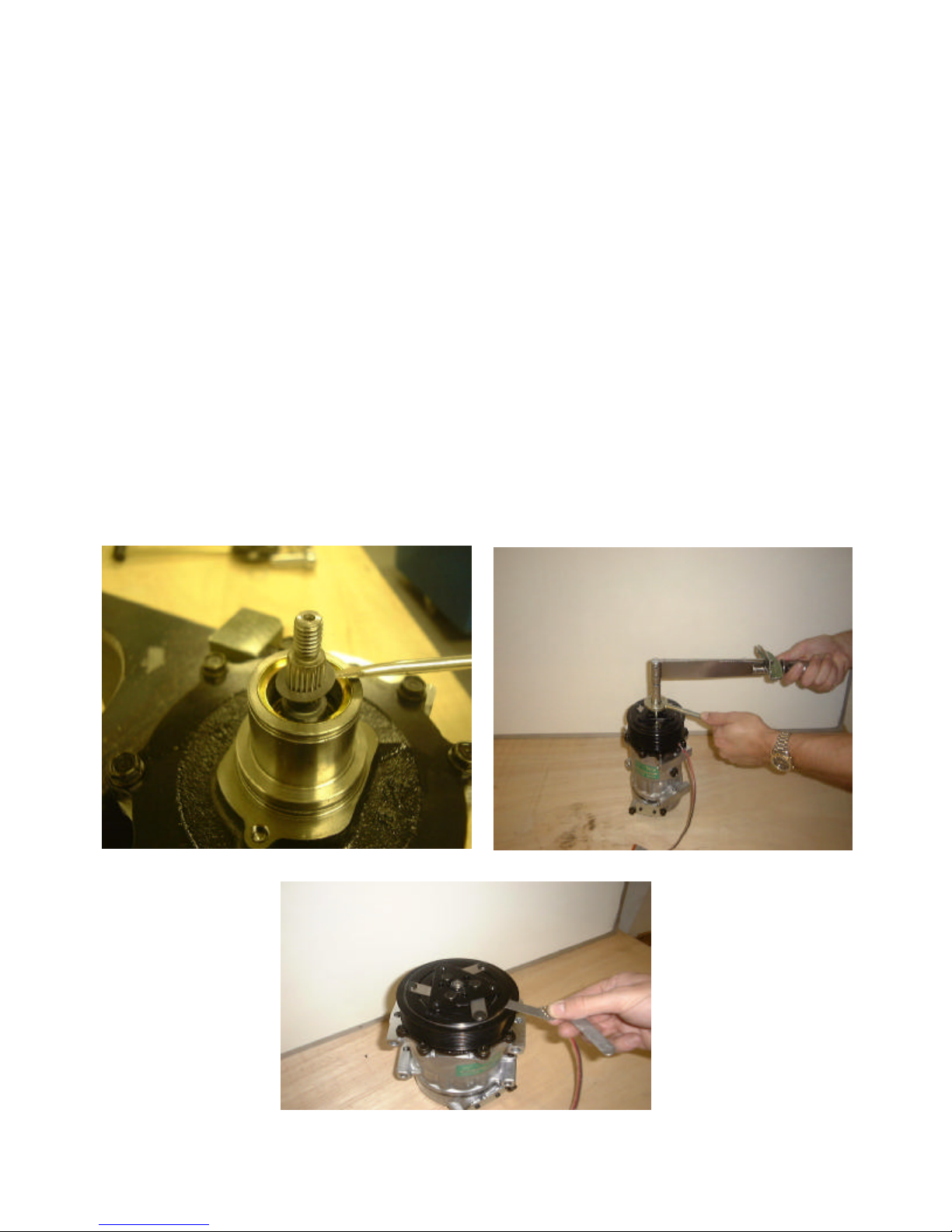
4. Place the driver into the ring and drive the rotor down onto the front
housing with a hammer or arbor press. Drive the rotor against the front
housing step. A distinct change of sound can be heard when using a
hammer to install the rotor.(Fig.9)
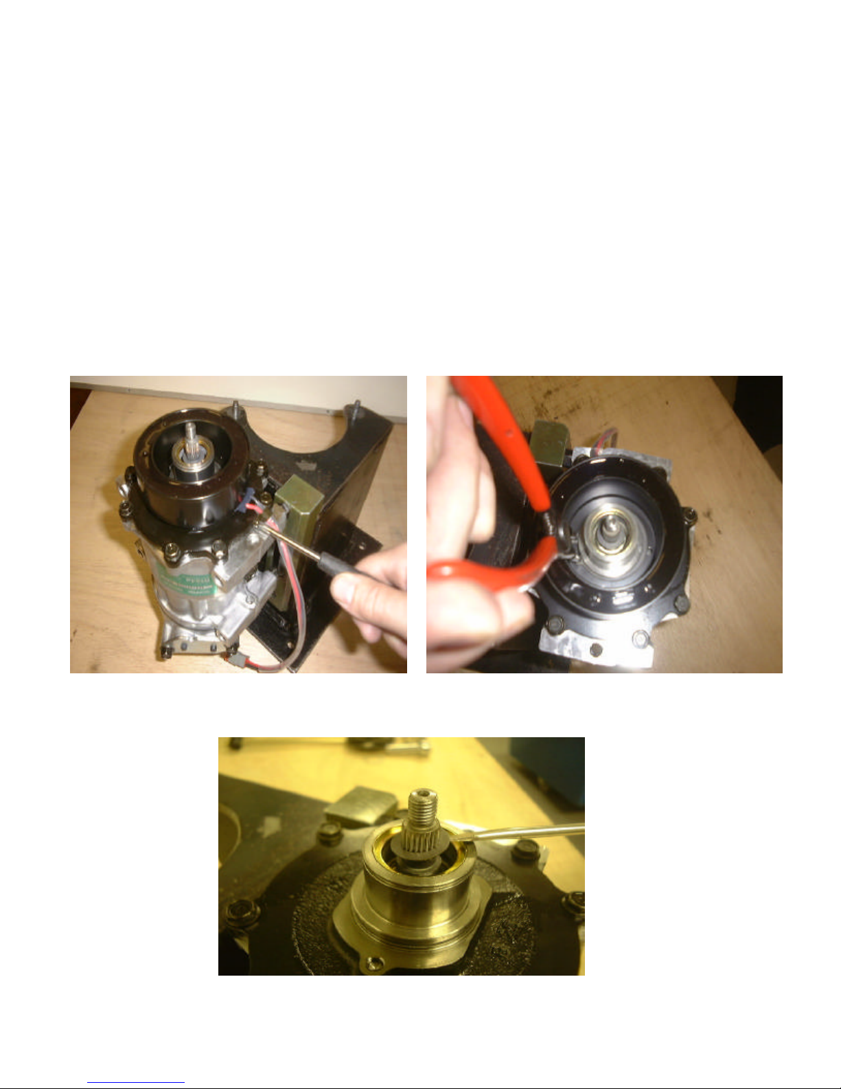
5. Reinstall the rotor retaining snap ring using snap ring pliers.(Fig.10)
6. Reinstall rotor bearing dust cover (if present) by gently tapping it into
place.
Fig.9 Installation of rotor using arbor press Fig.10 Re-install snap ring

SD7H15 Type C Service Manual
Prepared July 1999 – Application Engineering
10
Service Operations – Clutch
3.6 Armature Assembly Installation
1. Install clutch shims. Note: Clutch air gap is determined by shim
thickness. When installing a clutch on a used compressor, try the original
shims first. When installing a clutch on a compressor that has not had a
clutch installed before, first try 1.0, 0.5 and 0.1mm shims.(Fig.11)
2. Reinstall the armature on the splined shaft. Manually push the armature
down the shaft until it bottoms on the shims.
3. Replace retaining nut and torque to specification. M8- 18.0±3.0N•m
4. Check air gap with feeler gauge. Specification is 0.4-0.8mm. If air gap is
out of specification remove armature and change shims as
necessary.(Fig.13)
5. Replace armature dust cover (if used) Reapply thread lock and torque 3
bolts to 3.50±0.5N•m
Fig.11 Replace shims Fig.12 Torque armature retaining nut
Fig.13 Check air gap with feeler gauges

SD7H15 Type C Service Manual
Prepared July 1999 – Application Engineering
11
4. Service Operations – Shaft Seal
4.1 Replacement of Lip type shaft seal.
Note: Lip seal assembly and felt ring must never be reused.
Always replace these components.
1. Be sure all gas pressure inside the compressor has been relieved.
2. Remove clutch assembly as detailed in section A.
3. Remove the felt ring assembly using a small screwdriver to pry it
out.(Fig.14)
4. Remove seal snap ring with internal snap ring pliers.(Fig.15)
5. Use lip seal removal and installation tool to remove lip seal assembly.
Twist the tool until the 2 lips on the tool engage the slots in the lip seal
housing and pull the seal out with a twisting motion.(Fig.16) Clean out
shaft seal cavity completely. Make sure all foreign material is completely
removed.
Fig.14 Felt ring removal Fig.15 Snap ring removal
Fig.16 Shaft seal removal

SD7H15 Type C Service Manual
Prepared July 1999 – Application Engineering
12
Service Operations – Shaft Seal
6. Place shaft seal protector sleeve over compressor shaft. Inspect the sleeve
to ensure that it has no scratches and is smooth so that the lip seal will not
be damaged. Make sure there is no gap between the end of the sleeve and
the seal surface of the shaft (Fig.17).
Fig.17 Protector sleeve fitting
7. Engage the lips of the seal removal and installation tool with the slots in
the new lip seal housing. Make sure the lip seal assembly, especially the
O-ring is clean. Dip the entire lip seal assembly, on the tool, into clean
refrigerant oil. Make sure the seal assembly is completely covered with
oil.
8. Install the lip seal over shaft and press firmly to seat. Twist the tool in the
opposite direction to disengage it from the seal and withdraw the
tool.(Fig.18)
Fig.18 Replacement of lip seal
9. Reinstall shaft seal snap ring with internal snap ring pliers. Bevelled side
should face up. (Away from the compressor body). Ensure that the snap
ring is completely seated in the groove.
10.Tap new felt ring assembly into place.
11.Reinstall clutch assembly as detailed in section A.

SD7H15 Type C Service Manual
Prepared July 1999 – Application Engineering
13
5. Service Operations – Cylinder head
5.1 Cylinder head, valve plate removal and installation.
1. Be sure all internal compressor pressure has been relieved. This can be
achieved by undoing the oil plug slowly.
2. Remove cylinder head bolts.(Fig.19)
3. Use a small hammer and gasket scraper to separate the cylinder head
from the valve plate. Be careful not to scratch the gasket surface of the
cylinder head.
4. Carefully lift the cylinder head from the valve plate.(Fig.20).
Fig.19 Removal of cylinder head bolts Fig.20 Removal of cylinder head
5. It is recommended that both the head gasket (between the cylinder head
and the valve plate) and the block gasket (between the valve plate and the
cylinder block) be replaced at any time the cylinder head is removed.
However, if no service is required to the valve plate, it may be left in
place. If the valve plate comes loose from the cylinder block, the block
gasket must be replaced.
6. Carefully remove old head gasket from top of valve plate with gasket
scraper. Be careful not to disturb the valve plate to cylinder block joint if
valve plate is to be left in place. If valve plate comes loose from cylinder
block, proceed to section 5.2 Valve plate removal.

SD7H15 Type C Service Manual
Prepared July 1999 – Application Engineering
14
Service Operations – Cylinder head
5.2 Valve plate removal
1. Using a small hammer and gasket scraper carefully separate valve plate
from cylinder block. Be careful not to damage sealing surface of cylinder
block.(Fig.21)
2. Inspect reed valves and retainer. Replace valve plate assembly if any part
is damaged.
3. Carefully remove any gasket material remaining on valve plate, cylinder
block or cylinder head.
Fig.21 Removal of valve plate
5.3 Valve plate and cylinder head installation.
1. Coat new block gasket with clean refrigerant oil.
2. Install block gasket. Align new gasket to location pin holes and orifice(s).
Notch (if present) should face same direction as oil plug or adapter.
3. Place valve plate on cylinder block with discharge valve, retainer and nut
facing up (away from cylinder block) and location pins properly located
in holes.
4. Ensure that there is no residual oil in each bolt hole. If oil is present it
must be removed to prevent thread damage.
5. Coat head gasket with clean refrigerant oil.
6. Install head gasket over location pins, checking for correct orientation.
7. Install cylinder head.

SD7H15 Type C Service Manual
Prepared July 1999 – Application Engineering
15
Service Operations – Cylinder head
8. Install cylinder head bolts and tighten in a star pattern.(Fig.22)
Torque first to approximately 20.0N•m, then finish by torquing to
34.0 ±5.0N•m (Fig.23)
Fig.22 Torque sequence of cylinder head bolts
Fig.23 Torquing cylinder head bolts

SD7H15 Type C Service Manual
Prepared July 1999 – Application Engineering
16
Table of contents
Other Sanden Air Compressor manuals
Popular Air Compressor manuals by other brands

GEA
GEA HG4/310-4 Assembly instructions

Hitachi
Hitachi EC119 OM Safety and instruction manual

NARDI COMPRESSORI
NARDI COMPRESSORI Diving Hookah Operation and maintenance manual

Ingersoll-Rand
Ingersoll-Rand M200-LV Operation and maintenance manual

Campbell Hausfeld
Campbell Hausfeld VS260000KB operating instructions

Campbell Hausfeld
Campbell Hausfeld HL5404 Operating instructions and parts manual

Protocol
Protocol 250 PSI instruction manual

RIDGID
RIDGID OF45200SS Operator's manual

Brownie’s
Brownie’s Yacht Pro 135 Operator's manual

Gardner Denver
Gardner Denver VS45A Operating and service manual

Badger Air-Brush
Badger Air-Brush 80-7 User and maintenance instructions

AstroAI
AstroAI ATJ-8366 user manual