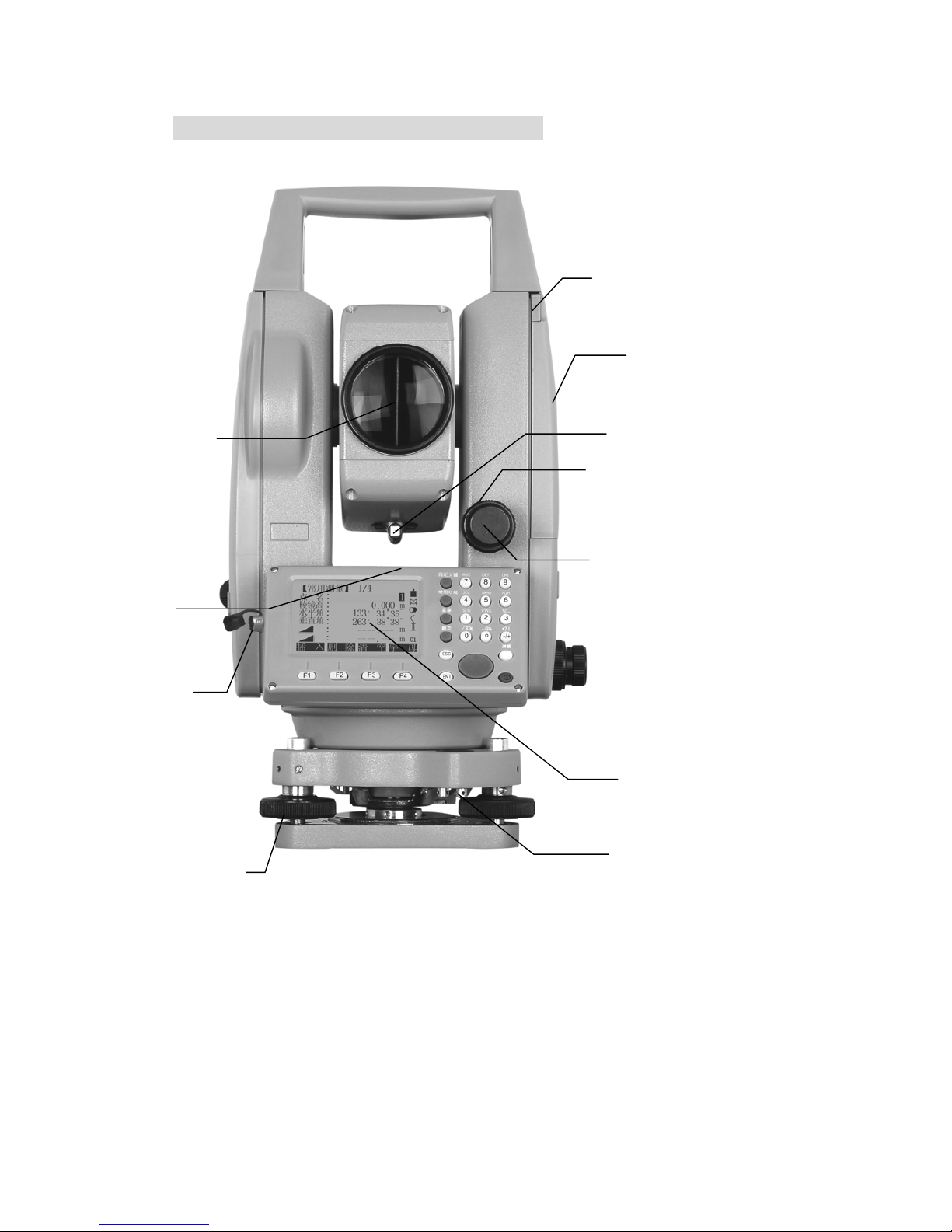
5) Navigation key
6) Soft key (Functions vary accor )
7) Soft function key (displa start-up relevant function. It can
use to start-up figure and
8) Measure hot key (importan
9) Power key
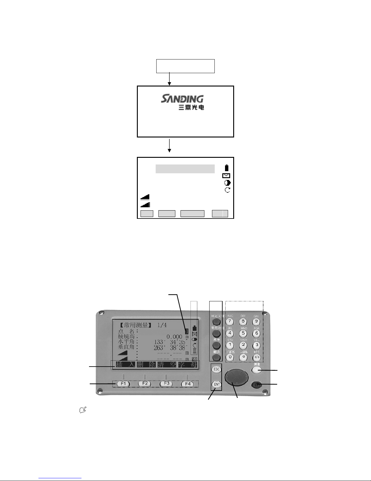
FIXED KEY
[User key]:User key can be defined. Can select the function of this key from “common
function could be started up directly in different application.
tion in menu could be appointed in user key(see“4.4 main setting”)
u ]:Menu setting, data management, communication
p ransmission, etc.
ding to the message displayed.
y relevant operation function, use to
character function in STS-720)
t key)
1.4
function” menu.
[function ]:Measurement key in common use. Several functions could be called up, the
instruction as follows:
·
·every func
[ Men key. Calling program, parameter
arameter, instrument adjustment, system information and data t
In the m many choices, there is shortcut figure viewed at the right of every
ce
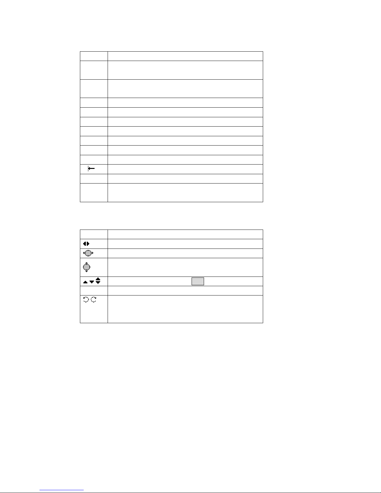
[ PAGE ] there are several pages in one dialog box, it can be used to page.
] lay.
] to next step.
1.5M E
rem three functions “measure & record”,
“m in Settings or Main Settings.
1.6 SOFT
Th s of the display, orders and the
soft k at gh corresponding function key. The
meaning ach
enu including
choi , use the shortcut figure to start up directly, no need to page.
:Page key.When
[ ESC :Return to the previous mode or disp
[ ENT :Confirm the inputting values, and enter in
EASUR MENT HOT KEY
Measu ent hot key (important key)can be set to
easure”, or “close”. The function can be activated
KEY
(
FUNCTION KEY
)
【General Measurement】1/4
PtID :A1
R.HT:1.500m
HR:0°00′00″
V:90°00′00″
:---.--- m Ⅰ
:---.--- m
ALL DIST RECORD ↓
SetStn EDM ↓
SetHz TILT BEEP ∣←
e measurement data is displayed in the several upper line
eys are the bottom line, which can be activated throu
of e soft key depends on current activated application and function.
4