Sandr Garden GBL 26 User manual

1/112
GBL 26
6021440/112
[B00325-02]
GB 26
DECESPUGLIATORI
BRUSHCUTTERS
DEBROUSSAILLEUSES
FREISCHNEIDER
STRUIKENSNOEIERS
DESBROZADORAS
ROÇADORAS
KOSIARKA
MANUALE ISTRUZIONI
INSTRUCTION MANUAL
MODE D'EMPLOI
BEDIENUNGSSANLEITUNGEN
GB
I
F
D
NL
E
P
PL
BEDIENINGSHANDLEIDING
MANUAL DE INSTRUCCIONES
MANUAL DE INSTRUÇÕES
INSTRUKCJA OBS£UGI
Leggere attentamente le presenti
istruzioniprimadelprimoimpiego.
Readthisoperatorsmanualcareful
beforethefirstuse.
Lireavecattentioncesinstructions
avantlapremièreutilisation
VorderAnwendungdievorliegenden
Anweisungenaufmerksamlesen.
Lees aandachtig deze instructies
dooralvorenshetapparaatvoorhet
eerstingebruiktenemen.
Leer con cuidado estas
instrucciones antes de la primera
utilización.
Leiacomatençãoestasinstruçõesantes
deutilizarpelaprimeiravezoaparelho.
Przed pierwszym u¿ytkowaniem
uwa¿nie przeczytaæ niniejsz¹
instrukcjê.
I
GB
F
D
NL
E
P
PL
GBL 34
GB 34

2/112
(I)
ATTESTAZIONE DI CONFORMITÀALLE NORME CEE
Lasottoscritta SANDRIGARDEN srl, viaManzoni 22,36027 ROSÀ(VI)ITALIA,dichiarache iseguentiprodotti:
DECESPUGLIATORI CON MOTORE A SCOPPIO GB 26, GBL 26, GB 34, GBL 34 sono conformi alle
direttive,98/37/CEE,89/336/CEE,edèstatosviluppatoconformementeallenormeENISO11806
(ENG)
EC DECLARATION OF CONFORMITY
The under signed SANDRIGARDEN srl, via Manzoni 22, 36027 ROSÀ(VI) ITALIA, declare that the following
products:COMBUSTIONENGINEDRIVENBRUSHCUTTERSGB26,GBL26,GB34,GBL34 areinaccordance
withthedirective98/37/EEC, 89/336/EECandasbeendevellopedinaccordancewiththestandarsENISO11806.
(F)
ATTESTATION DE CONFORMITE AUX NORMES CEE
La soussignéeSANDRIGARDEN srl, via Manzoni 22, 36027 ROSÀ(VI) ITALIE, déclare que ces produits
DEBROUSSAILLEUSEAVEC MOTEUR A EXPLOSION GB 26, GBL 26, GB 34, GBL 34 sont conformes aux
directives,98/37/CEE,89/336/CEE,etconçuselonlesnormesENISO11806
(D)
KONFORMITÄTBESCHEINIGUNGZUEWG-REGELUNGEN
DieunterschriebeneFirmaSANDRIGARDENsrl,viaManzoni22,36027ROSÀ(VI)ITALIEN,erklärthiermit,dass
folgendesProdukt::FREISCHNEIDEGERÄTEMITEXPLOSIONSMOTORGB26,GBL26,GB34,GBL 34 den
Richtlinien98/37/EWG,89/336/EWGentsprichtunddassesentsprechenddenStandardsENISO11806entwickelt
wurde.
(NL)
CONFORMITEITSVERKLARING MET DE CEE NORMEN
Ondergetekende SANDRIGARDEN srl, via Manzoni 22, 36027 ROSÀ(VI) ITALIË, verklaart dat de volgende
producten:STRUIKENSNOEIERSMETVERBRANDINGSMOTORGB26,GBL26,GB34,GBL34 conformzijn
aanderichtlijnen98/37/CEE,89/336/CEE,enontworpenzijninovereenstemmingmetdenormenENISO11806
(E)
CERTIFICACIÓN DE CONFORMIDAD CON LAS NORMAS CEE
LaabajofirmanteSANDRIGARDENsrl,viaManzoni22,36027ROSÀ(VI)ITALIA,declaraqueelsiguienteproducto:
DESBROZADORAS CON MOTOR DE EXPLOSIÓN GB 26, GBL 26, GB 34, GBL 34 son conformes a las
directivas,98/37/CEE,89/336/CEE,yhasidorealizadodeconformidadconlasnormasENISO11806.
(P)
ATESTADO DE CONFORMIDADE COMAS NORMAS CEE
A abaixo assinada SANDRIGARDEN srl, via Manzoni 22, 36027 ROSÀ(VI) ITÁLIA, declara que os seguintes
produtos: ROÇADORAS COM MOTOR DE EXPLOSÃO GB 26, GBL 26, GB 34, GBL 34 estão conforme as
directivas98/37/CEE,89/336/CEE,eforamdesenvolvidosdemaneiraconformeasnormasENISO11806
(PL)
CERTYF KAT ZGODNOC Z NORMAM CEE
Ja, ni¿ej popisany/a SANDRIGARDEN srl, ulica Manzoni 22, 36027 ROSA (V ) W£OCHY,
owiadcza, ¿e produkt: KOSIARKI Z SILNIKIEM ISKROWYM GB 26, GBL 26, GB 34, GBL 34
s¹ zgodne z dyrektywami 98/37/CEE, 89/336/CEE i zosta³y zbudowany zgodnie z normami
EN ISO 11806
05 - 11 - 2001
SANDRI GARDEN
srl
Direttore Generale
Alberto Cattaneo

3/112
14
22
8
9
Fig. 1
18
15 16 17
14
15
16
17
10
9
8
13 11
22
21
21
18
12
12 723
19
20
4
3
12
5
6
24
10
11

4/112
MANUALE ISTRUZIONIDECESPUGLIATORE
1. CONGRATULAZIONI
Gentilecliente,vogliamocongratularciconLeiper
aversceltounnostroprodottoperilgiardino.
Il Vostro DECESPUGLIATORE èstato
costruito,tenendocontodellenormedisicurezza
vigentiatuteladelconsumatore.
In questo manuale sono descritte ed illustrate le
varieoperazionidimontaggio, diusoedinterventi
dimanutenzione,necessaripermantenereinper-
fettaefficienzailVostroDECESPUGLIATORE.
PERFACILITARELALETTURA
Leillustrazionicorrispondential
montaggioealladescrizionedella
macchinasitrovanonelrisvoltodicopertina,all'ini-
ziodelpresentefascicolo.
Tenereapertequestepaginedurantelaletturadel-
leistruzionidimontaggioediutilizzo.
NelcasoilVostroDECESPUGLIATOREnecessi-
tassediassistenzaoriparazione,Vipreghiamodi
rivolgervialnostrorivenditore,oaduncentroassi-
stenzaautorizzato.
2. PRECAUZIONI FONDAMENTALI
DISICUREZZA
NORMEGENERALI
AVVERTENZE:
A1 -L'utilizzo del DECESPUGLIA-
TORErichiedeilrispettodellenormedi
sicurezza.
A2 - Chiunque utilizzi il
DECESPUGLIATOREdeveprimaleg-
gereattentamenteilmanualediistru-
zioniemanutenzioneefamiliarizzare
completamenteconicomandi per un
usocorrettodell'apparecchio.
A2.1- Conservareilpresentemanua-
leperconsultazionifuture.
A3 - Non permettere l'uso del
DECESPUGLIATORE ai bambini e
personechenonsianocompletamente
aconoscenzadellepresentiistruzioni.
PERICOLO:
A4-Fareattenzionealmaterialepro-
iettatodaldispositivoditaglio.
A5-Nonmettereinmotoenonutilizza-
reiltagliaerbainprossimitàdipersone,
animaliocose.
Duranteilfunzionamentosiraccoman-
daunadistanzaminimadi15mtrala
macchinaedaltrepersone.
A6-L'operatoreèresponsabileincaso
di incidenti o pericoli occorsi ad altre
personeodallelorocose.
UTILIZZO:B1-ImpiegareilDECESPUGLIATORE
solamentepertagliareerbaederbacce
ecespugli.
Nonimpiegarel'apparecchioperscopi
diversi.
B2-Indossareun'abbigliamentoedun
equipaggiamento di sicurezza adatto
all'utilizzodelDECESPUGLIATORE.
Durante l'utilizzo indossare abiti ade-
rentienonsciolti.
B3-Indossareocchialidiprotezioneo
visieraomologati.
B3.1-Indossareparaorecchidiprote-
zioneperilrumore,omologati.
B3.2-Indossareilcascodiprotezione
incasodirischiodicadutadioggetti.
B4-Calzarescarperobusteconsuole
nonsdrucciolevoli.
I

5/112
MANUALE ISTRUZIONIDECESPUGLIATORE
B5-Indossareguantirobusti.
B6 - Chi utilizza il DECESPUGLIA-
TORE deve essere in buona forma.
NON UTILIZZARE il DECESPU-
GLIATOREincondizionidistanchez-
za,dimalessereosottol'effettodell'alcol
edialtredroghe.
B7 - ATTENZIONE! I gas di scarico
sonovelenosiedasfissianti.Seinspi-
ratipossonoquindiessereanchemor-
tali.Nonfarefunzionareilmotoreinluo-
gochiusooscarsamenteventilato.
B8-L'utilizzoprolungatodell'apparec-
chiopuòcausaredisturbidicircolazio-
nesanguignaallemani(malattiadelle
ditabianche)attribuibiliallevibrazioni.
Fattoricheinfluisconosullamanifesta-
zionedeidisturbipossonoessere:
-Predisposizionepersonaledell'ope-
ratoreadunascarsairrorazionesan-
guignadellemani.
-Utilizzodell'apparecchioabassetempe-
rature(siconsiglianopertantoguanticaldi).
-Lunghitempidiutilizzosenzainterru-
zioni(siconsigliaunutilizzoadinterval-
li).
-Incasodimanifestazionediformicolio
eintorpedimentosiraccomandadicon-
sultareunmedico.
B8.1 - Sostenere l'apparecchio sem-
preconambeduelemani.
Assumereunaposizionestabileesicu-
rasullegambe.
B8.2-IlDecespugliatoreèprogettato
peressereutilizzatosulfiancodestro
dell'operatore(vedifig.37-38).
Tenerel'impugnaturaposteriore(coni
comandi)conlamanodestrael'impu-
gnaturaanterioreconlamanosinistra.
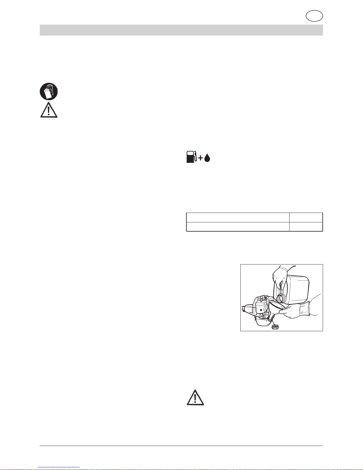
B9 - ATTENZIONE! la benzina e
isuoivaporisonoestremamenteinfiam-
mabili.
PERICOLO DI USTIONI ED INCENDIO.
B9.1-Arrestareilmotoreprimadelri-
fornimento.
B9.2 - Non fumare durante il riforni-
mentodicarburante.
B9.3 - Asciugare il carburante even-
tualmenterovesciato.Mettereinmotoil
motorelontanodalluogodirifornimento.
B9.4-Assicurarsicheiltappodelser-
batoiosiabenserrato.
Fareattenzioneadeventualiperdite.
B10-Conl'apparecchioèfornitauna
PROTEZIONEDELDISPOSITIVODI
TAGLIO (Fig.1 part.21) che deve es-
sere montata prima dell'utilizzo (vedi
istruzionidimontaggio).
Nonmettereinmotonèutilizzarel'ap-
parecchiosenonèprovvistodiprote-
zione.
B10.1 - PERICOLO! Feritedovute al
contattoconildispositivoditaglio;pro-
iezionedimaterialeversol'operatore.
Nonmodificarelaprotezione.
Sostituirelaprotezionesedanneggia-
ta,soloconunricambiooriginale.
B10.2 - PERICOLO! Non montare
filo metallico nella testa di taglio.
B10.3 - Il BLOCCODELCOMANDO
DELL'ACCELERATORE (vedi fig.1
part.16)impediscel'azionamentoacci-
dentaledellalevadell'acceleratore.
B10.4 - INTERRUTTORE (ON/OFF)
diarrestodelmotore(fig.1part.14).
PERICOLO!Attenzioneildispositivodi
taglio continua a girare per un certo
tempoanchedopol'azionamentodel-
l'interruttoresullaposizione"OFF".
I

6/112
MANUALE ISTRUZIONIDECESPUGLIATORE
Teneresaldamenteledueimpugnatu-
refinoalcompletoarresto.Vedicapito-
loAVVIAMENTOEDARRESTO.
B10.5 PERICOLO! Non montare
lamea sega.
B10.6 PERICOLO! Non montare
lamecostituitedapiùpezzimasolo
lamemonolitiche.
B10.7 PERICOLO! Non montare
lame con diametro superiore a
230mm.
3. DESCRIZIONI PARTI MACCHINA
DESCRIZIONE Fig.1
1) Manigliadellafunediavviamento
2) Avviatore
3) Levettadell'aria
4) Cappucciodellacandela
5) Tapposerbatoiocarburante
6) Silenziatore
7) Impugnaturasinistra(manubrio)
8) Motoreascoppio
9) Serbatoiocarburante
10) Impugnaturadestraconcomandi(manubrio)
11) Impugnaturacomandiposteriore
12) Puntodiattaccopercinghia
13) Impugnaturaanteriore
14) DispositivodiarrestodelmotoreON/OFF.
15) Bloccaggiomezzoacceleratore
16) Bloccodelcomandodell'acceletaore
17) Levadell'acceleratore
18) Tuboditrasmissione(asta)
19) Lama
20) Protezionedispositivoditaglio(perlama)
21) Protezionedispositivoditaglio(pertestaafili)
22) Dispositivoditaglio(testaafili)
23) Imbracaturaacinghia
24) Barriera
4. MONTAGGIO
IMPUGNATURA ANTERIORE PER MODELLO
GBL 26/34
1)Posizionarecomeillustratonellafig.2 l'impugna-
tura(part.1)ela barriera(part.2).
2)Bloccareconlen°4viti,rosetteedadi(fig.3)
La barriera ha la funzione di assicurare una
distanza di sicurezza tra l'operatore ed il di-
spositivo di taglio.
MANUBRIOCONIMPUGNATURAPERMODEL-
LOGB26/34
1) Il DECESPUGLIATORE viene imballato con il
manubrioripiegato(fig.4).
2) Allentareilpomolo(fig.5)e ruotare il manubrio
trasversalmente.
3)Bloccareilmanubrioserrandoafondoilpomolo
(fig.6).
Il manubrio puòessere ripiegato per comoditàdi
trasportoorimessaggiooltrechèregolatoperuna
piùcomodaposizionedilavoro.
IDECESPUGLIATORI possono essere
utilizzati:
A.Perdecespugliare,montandolalama elaprote-
zionedellalama(fig.1part.19-20).
B. Per il taglio di erba, montando la testa a fili e
l'estensione (fig.1 part.21-22), che viene avvitata
allastessaprotezione.
ATTENZIONE!Lecondizionidisicurez-
za previste dalle norme vigenti si veri-
ficano solo montando le protezioni come so-
pra descritto.
I

7/112
MANUALE ISTRUZIONIDECESPUGLIATORE
MONTAGGIOLAMAEPROTEZIONE(fig.7-8)
ATTENZIONE!Calzarei guantidisicu-
rezza per ogni intervento di montag-
gio e manutenzione sulla lama.
1)Inserireiduedadiquadratinellelorosedinella
protezione(fig.9).
2) Posizionare la protezione sotto alla scatola di
trasmissioneinalluminio(fig.10).
3)Posizionareilmorsettosuperioreebloccarecon
leviti(fig.11).
4)Avvitare(conle3viti)ilpiattellofissoallascatola
ditrasmissione(fig.12-13).
5) Infilareilpiattellosuperiore(inalluminiofig.14)
bloccalamasull'alberodiuscita.
6)Montareinsuccessionelalama(fig.15)(centrar-
lasull'appositasporgenzadelpiattello)equindiil
piattelloinferiore(fig.16)bloccalama,lacoppetta
(fig.17)elavitesinistra.
7)Serrareinsensoantiorarioconlachiaveindo-
tazione(fig.18).
MONTAGGIO TESTAA FILI E L'ESTENSIONE/
PROTEZIONE (fig.19-20)
1)Unirelaprotezione(fig.20part.1)all'estensione
(fig.20part.2)ebloccareconle3vitieidadi.
2)Montarelaprotezioneedilpiattellofissocome
descrittoneipunti1-2-3del paragrafo MONTAG-
GIOLAMAEPROTEZIONE.
3)Infilareilpiattellorotante(inplastica)sull'alberodi
uscita(fig.21).
4)Avvitare(insensoantiorario)latestaafili(fig.22).
5)Inserireuncacciavitenell'appositanicchia(fig.22
part.1)perbloccarel'alberoduranteilserraggio.
6)Serrarelatestaafili.
IMBRACATURA A CINGHIA E ANELLO DI AT-
TACCO(fig.23)
1)Fissarel'anelloinplasticacomeillustratoinfig.23.
2)Fissarlotramitelevitieidadi(fig.24).Primadella
messainmotoregolarelaposizionedell'anelloper
unbuonbilanciamento.
5. RIFORNIMENTO CARBURANTE
1)ATTENZIONE!L'apparecchioèequi-
paggiatodi motoreascoppioa2 tempi.
Ilmotoredeveesserealimentatoconunamisceladi
benzinaeoliopermotoria2tempi,nelleseguenti
percentuali.
Con olio normale per motore 2 tempi 1:25 (4%)
Con olio a base sintetica per motore 2 tempi 1:40 (2,5%)
2)Miscelareagitandoabbondantementeilconteni-
toreprimadiognirifornimento.
Fig.25
3) Preparare la
miscela carbu-
ranteefarerifor-
nimento solo al-
l'aperto(fig.25).
4)Conservareilcarburanteinuncontenitorepre-
vistoperquestousoecontappobenserrato.
6.AVVIAMENTOEARRESTO
ATTENZIONE!Osservarescrupolosa-
mente gli avvertimenti contenuti nel
precedenteCap.2PRECAUZIONIFONDAMEN-
TALI DI SICUREZZA.
I

8/112
MANUALE ISTRUZIONIDECESPUGLIATORE
AVVIAMENTOAMOTOREFREDDO
1) Premere l'interruttore di arresto (fig. 26) sulla
posizione"ON".
2)Sollevarelalevettadell'ariaposta a destradel
coperchiodelcarburatore(fig.27)eportarlanella
posizione .
3)Pressareafondoripetutamenteilbulboprimer(fig.
28)finoaquandoilcarburanteritornanelserbatoio
attraversoilsecondotubettotrasparente(fig.29).
4)Afferrarel'impugnaturapremendoconilpalmoil
bloccoacceleratore(fig.30),liberandoinquestomodo
ilmovimentodellalevaacceleratore(fig.30part.1).
5)Premereafondolalevadell'acceleratore(fig.31).
6)Mantenendopremuteleleve(fig.31)spingerea
fondoilbottonedelmezzoacceleratore(fig.32).
7)Mantenendoafondoilbottone rilasciarelaleva
dell'acceleratore.
Inquestomodoilbottonedibloccodelmezzoacce-
leratorerimaneinserito,quindilemanirimangono
entrambedisponibiliperl'avviamento.
8)Tirareafondofinoa3voltelamanigliadellafune
diavviamento(fig.33).
9)Spingereingiùlalevettadell'ariadelcarburato-
re (fig.34).
10) Tirare la fune di avviamento (fig.33) fino alla
messainmoto.
ATTENZIONE-PERICOLO!! Ilmotoresi
avviaerimaneacceleratoametàquindiil
dispositivoditaglioèinrotazione.
Lasciarefunzionareilmotoreperalcunisecondi.
11) Premendobrevementelalevaacceleratore(fig.
35 part.1) il bottone del mezzo acceleratore si
disinserisceautomaticamente.Ilmotorerimanecosì
inmotoalregimeminimoedildispositivoditagliosi
arrestadopounbrevetempo.
ARRESTOMOTORE
1)Perarrestareilmotore,portarel'iterruttore(fig.
35part.2)nellaposizione"OFF".
Fig.27
Fig.28 Fig.29
Fig.30 Fig.31
Fig.32
Fig.33
Fig.34 Fig.35
é
é
é
é
é
é
é
é
é
1
2
1
Fig.26
é
ON
OFF
ON
OFF
I

9/112
MANUALE ISTRUZIONIDECESPUGLIATORE
ATTENZIONE!ildispositivoditaglioconti-
nua a girare per un certo tempo anche
dopol'azionamentodell'interruttoresullaposizione
"OFF".Teneresaldamenteledueimpugnaturefino
alcompletoarresto.
AVVIAMENTOAMOTORECALDO
Procederecomeamotorefreddomaconlalevetta
dell'ariaabbassata (vedifig.34).
7. UTILIZZO
COME UTILIZZARE IL DECESPUGLIATORE
1)Agganciarel'imbracaturaacinghia(fig.36part.1)
all'anello(fig.36part.2).
2)Tenerel'apparecchiosulfiancodestrocomein-
dicatoinfig.37-38.
REGISTRAZIONE DELLA LUNGHEZZA DEL
FILO DI TAGLIO
Latestaafiliindotazioneèdeltipoaregolazione
manuale.
Primacheilfiloditagliosisiausuratofinoametà
lunghezza,ripristinarelalunghezzatirandoequin-
diruotandoilrocchetto(fig.39).
Nel caso la quantitàdi filo estratto fosse un pòin
eccesso,lalunghezzavieneautomaticamentere-
golatadall'appositalamettadurantelarotazione.
TAGLIODIERBA
Tenendolatestaditaglioparallelaalterreno,avan-
zareoscillandoadestraesinistra(fig.40).
Tenere il motore apienigiripereffettuareiltaglio
netto.
TAGLIO INTORNO AD OSTACOLI, PIANTE,
RECINZIONI
Sfiorarel'ostacoloconl'estremitàdelfilo(fig.40).L'in-
clinazionedellatesta(fig.41)puòmigliorarel'effi-
cienzadeltaglio.Nonurtaregliostacoliconlatesta
ditaglioperevitarerotturenettedeifili.
In caso di rottura dei fili procedere come per la
sostituzione.
8. SOSTITUZIONE DEL FILO
Perriavvolgereunnuovofilosulrocchettoorigina-
le.
A)Utilizzarefilodidiametro2mminplasticaapposi-
topertagliaerbaafilo.
ATTENZIONEPERICOLO!NONUTILIZ-
ZAREASSOLUTAMENTEFILOMETAL-
LICO.EFFETTUAREL'OPERAZIONEA
MOTOREFERMO
B)SMONTAGGIOBOBINA
1)Svitareinsensoorarioildadoagalletto(fig.42).
2)Sfilareilrocchetto (fig.43-44-45).
3)Pulireaccuratamentel'internodelcorpo(fig.46).
C) AVVOLGIMENTO DEL FILO
1)Preparareduetrattidifilononsuperioria6m.
2)Infilarel'estremitàdeiduefilinegliappositi2fori
(fig.47).
3)Avvolgereiduetrattidifiloaccoppiatisulrocchet-
to,seguendoilsensodellafrecciaimpressasulroc-
chettostesso(fig.48).
4) Per facilitare il reinserimento del rocchetto nel
corpo,fissareledueestremitàdelfilonelledueap-
positeferitoie(fig.49).
D)RIMONTAGGIOROCCHETTO
1)Infilareiduecapiattraversoipassafilo(fig.50).
2) Inserire il rocchetto e tirare decisamente i due
capidelfiloperchèsisfilinodalleferitoie(fig.51).
3)Riposizionarelamolla(fig.52)eriavvitareildado
agallettoinsensoantiorario(fig.53).
I

10/112
9. MANUTENZIONE
CANDELA
Almenounavoltaall'annoodincasodidifficoltàdi
messainmoto,verificarelostatodellacandeladi
accensione.Attenderecheilmotoresiraffreddipri-
madell'operazione.
1) Sfilare il cappuccio e svitare la candela con la
chiaveindotazione(fig.54).
Incasodieccessiveincrostazionienotevoleusura
deglielettrodi,sostituirelacandelaconunaditipo
equivalente(fig.55-56).
Uneccessodiincrostazionipuòesseredovutaa:
#Eccessivapercentualediolionelcarburantee/o
qualitànonappropriatadell'olio.
#Filtroariaparzialmenteostruito.
2)Avvitarelacandelaamanofinoafondofilettoper
evitaredanniallasuasede.Usarel'appositachia-
vesoloperilserraggio(fig.54).
FILTRO ARIA
Pulireperiodicamenteilfiltroaria;frequentemente
sesioperainareepolverose.
1)Svitarelaviteagallettodelcoperchio(fig.57).
2)Lavareconacquaedetergenteneutro.
3) Fare asciugare il filtro prima di riposizionarlo
(fig.58).
Sostituire il filtro se danneggiato per non
compromettere la durata del motore.
FILTROPESCANTEDELCARBURANTE
Sostituireunavoltaall'annoilfiltroestraendolocon
ungancioattraversol'aperturadirifornimentodel
serbatoio.
RETINA PARASCINTILLE DEL SILENZIATO-
RE
#Nelforodiscaricodelgasèinseritounanellocon
retina(partepiùsporgente).
# A causa dei depositi la retina tende a ostruirsi
riducendonotevolmenteleprestazionidelmotore.
#Estrarrel'anelloconretinapermezzodiunapinza
abecchi(fig.59).
REGIME MINIMO DEL MOTORE
#Verificareadogniutilizzochealregime-
minimoildispositivoditagliononsiainrota-
zione.
#Setendearuotarerivolgersiaduncentrodiassi-
stenzaperl'interventodiregolazione.
VERIFICA VITI E PARTI ROTANTI
#Primadiogniutilizzocontrollarechenoncisiano
viti o parti allentate e che non ci siano cricche o
notevoliusureneldispositivoditaglio.
#Sostituirelepartidanneggiateprimadell'utilizzo.
PULIZIA TRASPORTO E RIMESSAGGIO
# In caso di interruzione di utilizzo superiore a 2
mesi,vuotareilserbatoiodelcarburante.
#Nonpulireconliquidiaggressivi.
#Conservarel'apparecchioinluogoasciuttoesi-
curononaccessibileaibambini.
#Inoccasioneditrasportovuotareilserbatoiocar-
buranteeproteggerelalama(semontata)conun
appositaprotezione.
MANUALE ISTRUZIONIDECESPUGLIATORE
I

11/112
MANUALE ISTRUZIONIDECESPUGLIATORE
I
DATI TECNICI GBL 26
Massa 4,8 Kg
(senza carburante - dispositivo di taglio - protezione)
Capacitàserbatoio 700 cm3
Dispositivoditaglio(testaafili) 420 mm
Dispositivoditaglio(lama) 230 mm
Cilindratamotore 25,5 cm3
Potenzamassima 0,75 Kw
Regimemassimodelmotore 9.500 1/min
Regimemassimodeldispositivoditaglio 7.5001/min
Regimediminimo 2.800 1/min
Livellodipressioneacustica 98 dB(A)
LpA av (EN 7917)
Livellodipotenzaacustica 108dB(A)
LwA av (ISO 10884)
Livello vibrazioni max [testa a fili] 9,9 m/s2
(ISO 7916)
Livello vibrazioni max [lama] 10,6 m/s2
(ISO 7916)
DATI TECNICI GB 26
Massa 4,9 Kg
(senza carburante - dispositivo di taglio - protezione)
Capacitàserbatoio 700 cm3
Dispositivoditaglio(testaafili) 420 mm
Dispositivoditaglio(lama) 230 mm
Cilindratamotore 25,5 cm3
Potenzamassima 0,75 Kw
Regimemassimodelmotore 9.500 1/min
Regimemassimodeldispositivoditaglio 7.5001/min
Regimediminimo 2.800 1/min
Livellodipressioneacustica 98 dB(A)
LpA av (EN 7917)
Livellodipotenzaacustica 108dB(A)
LwA av (ISO 10884)
Livello vibrazioni max [testa a fili] 9,6 m/s2
(ISO 7916)
Livello vibrazioni max [lama] 10,4 m/s2
(ISO 7916)
DATI TECNICI GBL 34
Massa 5,9 Kg
(senza carburante - dispositivo di taglio - protezione)
Capacitàserbatoio 830 cm3
Dispositivoditaglio(testaafili) 420 mm
Dispositivoditaglio(lama) 230 mm
Cilindratamotore 33,6 cm3
Potenzamassima 1 Kw
Regimemassimodelmotore 9.500 1/min
Regimemassimodeldispositivoditaglio 7.5001/min
Regimediminimo 2.800 1/min
Livellodipressioneacustica 97 dB(A)
LpA av (EN 7917)
Livellodipotenzaacustica 107 dB(A)
LwA av (ISO 10884)
Livello vibrazioni max [testa a fili] 8 m/s2
(ISO 7916)
Livello vibrazioni max [lama] 8,9 m/s2
(ISO 7916)
DATI TECNICI GB 34
Massa 6,0 Kg
(senza carburante - dispositivo di taglio - protezione)
Capacitàserbatoio 830 cm3
Dispositivoditaglio(testaafili) 420 mm
Dispositivoditaglio(lama) 230 mm
Cilindratamotore 33,6 cm3
Potenzamassima 1 Kw
Regimemassimodelmotore 9.500 1/min
Regimemassimodeldispositivoditaglio 7.5001/min
Regimediminimo 2.800 1/min
Livellodipressioneacustica 97 dB(A)
LpA av (EN 7917)
Livellodipotenzaacustica 107 dB(A)
LwA av (ISO 10884)
Livello vibrazioni max [testa a fili] 5,6 m/s2
(ISO 7916)
Livello vibrazioni max [lama] 6,2 m/s2
(ISO 7916)

12/112
1. CONGRATULATIONS
DearClient-Maywecongratulateyouforhaving
chosenoneofourproductsforyourgarden.
Your GBL 26/34,GB26/34 BRUSH CUTTERS
has been manufactured in accordance with the
current safety regulations which protect the
consumer.
Thismanualdescribesandillustratesthevarious
operationsforassembly,useandmaintenancewhich
are required in order to keep your BRUSH
CUTTERSinperfectcondition.
TOFACILITATEREADING
Theillustrationsabouttheassembly
are to be found on the back of
cover,atthebeginningofthisbooklet.Keepthese
pagesopenwhilereadingtheassemblyinstructions.
Should your BRUSH CUTTERS need servicing
or repair, please contact your retailer or an
authorisedservicecentre.
2.ESSENTIAL SAFETY PRECAU-
TIONS
GENERALREGULATIONS
PRECAUTIONS:
A1-Safetyregulationsmustbeheeded
whenusingtheBRUSH CUTTERS.
A2-AllusersoftheBRUSHCUTTERS
mustfirstcarefullyreadthemaintenance
andoperatingmanualandfamiliarise
themselves fully with all controls for
correctoperationofthedevice.
A2.1 - Keep this manual for future
reference.
A3 - Do not let children and persons
whoarenotcompletelyawareofthese
instructions use the BRUSH
CUTTERS.
DANGER: A4 - Beware of objects hurled by the
linehead.
A5-Donotstartupanddonotusethe
grass trimmer near people, other
animalsorobtrusiveobjects.
During operation we recommend
keeping a minimum distance of 15 m
betweenthemachineandotherpeople.
A6 - The operator is responsible for
any accidents or hazards that may
occur to other persons or their
belongings.
OPERATION:
B1-UsetheBRUSHCUTTERonlyto
cutgrass,weedsandbushes.
Do not use the device for other
purposes.
B2 - Wear clothing and safety gear
suitable for BRUSH CUTTERS
operation.
During operation wear close-fitting
clothing and not loose or baggy
garments.
B3-Wearapprovedprotectivegoggles
orvisor.
B3.1-Wearapprovednoise-damping
earplugs.
B3.2 - Wear a safety helmet in areas
whereobjectsarelikelytofall.
B4 - Wear sturdy shoes with non-slip
soles.
B5-Wearsturdygloves.
B6-BRUSHCUTTERSoperatorsmust
beingoodphysicalcondition.DONOT
USEtheBRUSHCUTTERSifyoufeel
BRUSHCUTTERSOPERATINGMANUAL
GB

13/112
BRUSHCUTTERSOPERATINGMANUAL
tired, ill or are under the influence of
alcoholorotherdrugs.
B7 - CAUTION! Exhaust fumes are
toxicandasphyxiating.Ifinhaled,these
fumesmayevenbelethal.Donotstart
theengineinclosedorpoorlyventilate
environments.
B8-Prolongeduseofthedevicemay
hinder blood circulation to the hands
(Raynaud’s phenomenon) due to
vibrations.
Thefollowingfactorsmayposeariskto
theoperator’shealth:
-Operatorispredisposedtopoorblood
circulationinthehands.
-The device is used in cold weather
(warm gloves are strongly
recommended).
-Thedeviceisusednon-stopforlong
periods (we suggest using it at
intervals).
-Ifyoufeelatinglingsensationornumb
in any way, please seek medical
attention.
B8.1-Alwaysholdthedevicewithboth
hands.
Standinasafeandsteadyposition on
bothlegs.
B8.2- Thegrasstrimmerisdesigned
tobeusedonyourright-handside(see
fig.37-38).
Holdtherearhandlewithcontrolswith
your right hand and the front handle
withyourlefthand.
B9- CAUTION!Petrolanditsvapours
arehighlyflammable.
BURNING AND FIRE HAZARDS.
B9.1-Stoptheenginebeforerefuelling.
B9.2-Donotsmokewhilerefuelling.
B9.3-Wipeoffanyfuelthatmayhave
spilled.Startuptheengineawayfrom
theplacewhereitwasrefuelled.
B9.4 - Make sure the tank cap is
tightenedproperly.
Bewareofanyleaks.
B10 - The device is supplied with a
CUTTING ATTACHMENT GUARD
(Fig.1 item21) that must be mounted
before operation (see assembly
instructions).
Donotstartuporusethedeviceifitis
notequippedwiththeguard.
B10.1-DANGER!Injuriescausedby
contact with the line head. Guard
against objects hurled towards the
operator.
Donotmodifytheguard.
Ifdamaged,replacetheguardonlywith
anoriginalsparepart.
B10.2 - DANGER! Do not fit metal
wire in the line head.
B10.3 - The THROTTLE TRIGGER
LOCKOUT (see fig.1 item 16) stops
accidental operation of the throttle
controllever.
B10.4 - Engine power ON/OFF
SWITCH(fig.1item14).
DANGER! Caution! The line head
continuestospinforawhileevenafter
thepowerswitchhasbeenshutOFF.
Holdbothhandlesfirmlyuntiltheline
headcomes to a completestop. See
section titled STARTING AND
STOPPING.
B10.5DANGER!Donotfitsawblades.
B10.6 DANGER! Do not fit blades
composedofmanypartsbutonlysingle
blades.
GB

14/112
B10.7 DANGER! Do not fit blades
with a diameter greater than 230
mm.
3. DESCRIPTIONS OF MACHINE
PARTS
DESCRIPTION Fig.1
1) Startergrip
2) Starter
3) Chocklever
4) Sparkplugcap
5) Fuelcap
6) Silencer
7) Leftgrip(handlebar)
8) Combustionengine
9) Fueltank
10) Righthandlewithcontrols(handlebar)
11) Rearhandlewithcontrols
12) Suspensionpoint
13) Fronthandle
14) Enginestoppingdevice(OFF/ONswithc).
15) Throttlelock
16) Throttletriggerlockout
17) Throttlecontrollever
18) Shafttube
19) Blade
20) Cuttingattachmentguard(forblade)
21) Cuttingattachmentguard(forlinehead)
22) Linehead
23) Beltharness
24) Barrier
4.ASSEMBLY
FRONTHANDLEFORMODELGBL 26/34
1)Positionthehandle(item1)andtheguard(item
2)asillustratedinfig.2.
2)Clampwith4screws,washersandnuts(fig.3)
The guard is used to maintain a safe distance
betweentheoperatorandthecuttingtool.
HANDLEFORMODELGB 26/34
1)TheBRUSHCUTTERispackagedwithafolded
handle(fig.4).
2) Loosen the knob (fig.5) and turn the handle
crosswise.
3)Lockthehandlebytighteningtheknob(fig.6)fully.
Thehandlecanbefoldedbackforeaseoftransport
or storage and can be adjusted for a more
comfortableworkingposition.
BRUSH CUTTERS GB 26/34 and GBL 26/34
may be used:
A.Totrimbushes,byfittingtheblade andtheblade
guard(fig.1item19-20).
B. To trim grass by fitting the line head and the
extension(fig.1item21-22),thatisscrewedontothe
sameguard.
CAUTION! Safe operating conditions
established by effective regulations
are only met if guards are fitted as
described above.
BLADE AND GUARD ASSEMBLY (fig.7-8)
CAUTION! Wear safety gloves for
assemblyandmaintenancejobsonthe
blade.
1)Fitthetwosquarenutsintotheirthreadsonthe
guard(fig.9).
BRUSHCUTTERSOPERATINGMANUAL
GB

15/112
2) Place the guard under the aluminium gearbox
(fig.10).
3)Placethetopclampandlockwithscrews(fig.11).
4)Screwthefixeddeflectorontothegearbox(fig.12-
13)(with3screws).
5) Insert the alluminium blade-lock upper collar
(fig.14)inthedriveshaft.
6)Inthefollowingorderfittheblade(fig.15)(centre
itonthenibofthecollar)andthenthe (fig.16)blade
locklowerflange,theplate(fig.17)andtheleftscrew.
7)Tightenanticlockwisewiththewrenchprovided
(fig.18).
LINE HEAD ASSEMBLY AND EXTENSION /
GUARD (fig.19-20)
1) Join the guard (fig.20 item 1) to the extension
(fig.20item2)andclampwith3screwsandnuts.
2) Assemblethe guard and the fixeddeflector as
described in points 1-2-3 of the paragraph titled
BLADEANDGUARDASSEMBLY.
3)Installthe(plastic)rotaryflangeinthedriveshaft
(fig.21).
4)Screwonthelinehead(fig.22)anticlockwise.
5)Insertascrewdriverintherelevantnotch(fig.22
item1)tolocktheshaftwhentighteningattachments.
6)Tightenthelinehead.
BELT HARNESS AND SUSPENSION RING
(fig.23)
1)Attachtheplasticringasillustratedinfig.23.
2) Attach it with screws and nuts (fig.24). Before
startingthebrushcutter,adjustthepositionofthe
ringtoensuregoodbalance.
BRUSHCUTTERSOPERATINGMANUAL
5. REFUELLING
1) CAUTION! Thedeviceisequipped
withatwo-strokeengine.
Theenginemustbesuppliedwithamixtureofpetrol
andoilfortwo-strokeenginesinthefollowingratios.
Withnormaloilfortwo-strokeengines 1:25 (4%)
Withsyntheticoilfortwo-strokeengines 1:40 (2.5%)
2) Mix by stirring the container thoroughly before
refillingthetank.
3)Preparethefuelmixtureandonlyrefueloutdoors
(fig.25).
4) Store the fuel in a container set aside for this
purposeandwithtightlysealedcap.
Fig.25
GB

16/112
6.STARTINGANDSTOPPING
CAUTION! Strictly heed the warnings
outlined in the chapter 2 above titled
ESSENTIALSAFETYPRECAUTIONS.
COLDENGINESTARTUP
1)Pressthestopbutton(fig.26)tothe“ON”position.
2) Lift the choke lever located to the right of the
carburettorcover(fig.27)andplaceitinthe
position.
3)Repeatedlypresstheprimerbulb(fig.28)down
untilthefuelreturnstothetankthroughthesecond
transparenthose(fig.29).
4)Gripthehandleby pressing the throttletrigger
lockout(fig. 30) with thepalmofyour hand, thus
allowingyou to move throttle controllever (fig.30
item1)freely.
5)Pressthethrottlecontrollever rightdown(fig.31).
6)Holdthelevers(fig.31)downandpushthethrottle
lockbutton(fig.32)rightdown.
7) Hold the button down and release the throttle
controllever.
Thisshouldlockthethrottlelockbutton,sobothhands
arefreetooperatethedevice.
8)Pullthestartergrip(fig.33)completelyasmany
as3times.
9)Pushthecarburettorchokelever(fig.34)down
.
10)Pullthestartcord(fig.33)untiltheenginestartsup.
CAUTION-DANGER!! Theenginestarts
athalfaccelerationandasaresulttheline
headisspinning.
Lettheenginerunafewseconds.
11) Press the throttle contol lever briefly (fig. 35
item1) and the throttle lock button will disengage
automatically.Theenginewillthusreturntoidleand
thelineheadwillstopafterashortwhile.
BRUSHCUTTERSOPERATINGMANUAL
Fig.27
Fig.28 Fig.29
Fig.30 Fig.31
Fig.32
Fig.33
Fig.34 Fig.35
é
é
é
é
é
é
é
é
é
1
2
1
Fig.26
é
ON
OFF
ON
OFF
STOPENGINE
1)Tostoptheengine,shutthepowerswitch(fig.35
item2)“OFF”.
GB

17/112
CAUTION!Thelineheadcontinuestospin
forawhileevenafterthepowerswitchhas
beenshutOFF.Holdbothhandlesfirmlyuntilthe
lineheadcomestoacompletestop.
WARM ENGINESTARTUP
Proceedaswithacoldenginestartupbutwiththe
chokeleverdown (seefig.34).
7.OPERATION
HOW TO USE THE BRUSH CUTTERS
1)Couplethebeltharness(fig.36item1)tothering
(fig.36item2).
2)Holdtheapplianceontherightsideasshownin
fig.37-38.
ADJUSTING THE LENGTH OF THE CUTTING
LINE
Thelineheadsuppliedrequiresmanualadjustment.
Beforethecuttinglinehaswornasfarashalfway
restore the length by pulling and then turning the
spool(fig.39).
Iftoomuchlineispulledout,thelengthisautomatically
adjustedbythelimiterbladeduringrotation.
TRIMMING GRASS
With the line head held parallel to the ground,
proceedswingingthetrimmertotherightandleft
(fig.40).Keeptheenginerunningatfullspeedfora
cleantrim.
TRIMMING AROUND OBSTACLES, PLANTS
AND FENCES
Keeptheendoftheline(fig.40)justclearofobstacles.
The inclination of the head (fig. 41) may improve
trimmingefficiency.Donotknockobstacleswiththe
lineheadtoavoidcuttinglines.
Shouldlinessnap,replacethemasoutlinedbelow.
8.REPLACINGACUTTING LINE
Forrewindinganewlineontheoriginalspool:
A) Use a plastic line 2 mm in diameter specially
designedforstrimmers.
ATTENTION DANGER! DO NOT USE
METAL WIREATALL! DO THIS JOB
WITH THE ENGINE OFF
B)DETACHINGASPOOL
1)Unscrewthewingnut(fig.42)clockwise.
2)Removethespool (fig.43-44-45).
3) Thoroughly clean the inside of the housing
(fig.46).
C) WINDING A LINE
1) Prepare two sections of line not over 6 m in
length.
2) Insert the end of the two lines into the 2 holes
(fig.47)provided.
3)Windthetwocoupledlengthsoflineonthespool,
followingthe direction ofthe arrow printedon the
spoolitself(fig.48).
4) To make it easier to reinstall the spool in the
housing,attachbothendsofthelineinthetwoslots
provided(fig.49).
D) REFITTING A SPOOL
1) Insert both ends through the guiding eyelet
(fig.50).
2) Install the spool and pull boths end of the line
firmlyuntiltheyhangoutoftheslots(fig.51).
3)Refitthespring(fig.52)andscrewthewingnut
back(fig.53)onanti-clockwise.
BRUSHCUTTERSOPERATINGMANUAL
GB

18/112
9.MAINTENANCE
SPARKPLUG
Atleastonceayearoriftheenginehasproblems
startingupproperly,checktheconditionofthespark
plug.Waitfortheenginetocoolbeforeoperation.
1) Remove the cap and unscrew the spark plug
withthewrenchprovided(fig.54).
Iftheelectrodesareexcessivelysoiledorarevery
worn, replace the spark plug with an equivalent
(fig.55-56).
Excessivesoilingmaybedueto:
#Theoilratiousedinfuelistoohighand/oroilisnot
ofanappropriatetype.
#Airfilterispartlyclogged.
2)Screwthesparkplugmanuallyasfaraspossible
to avoid damaging its socket. Use the wrench
providedonlytotightenit(fig.54).
AIR FILTER
Cleantheairfilterperiodicallyorfrequentlywhen
workingindustyareas.
1)Unscrewthewingnutfromthecover(fig.57).
2)Washwithwaterandneutraldetergent.
3)Drythefilterbeforereplacingit(fig.58).
Replace the filter if it is damaged so as not
compromise engine life.
FUEL INTAKE FILTER
Replacethefilteronceayearbyremovingitwitha
hookthroughtank-refillingoutlet.
SILENCER SPARK ARRESTER SCREEN
#Aringwithascreenisinsertedintheexhaustgas
outlet(outermostpart).
#Depositstendtoblockthescreenandconsiderably
reduceengineperformance.
#Remove the ring with a screen using a pair of
pliers(fig.59).
BRUSHCUTTERSOPERATINGMANUAL
ENGINE IDLING SPEED
#Beforeuse,alwaysmakesuretheline
headdoesnotturnwhentheengineisidling.
# If it tends to turn, contact a service centre for
adjustment.
CHECKING SCREWS AND ROTATING PARTS
#Beforeuse,alwaysmakesuretherearenoscrews
or loose parts and there are no cracks or worn
sectionsinthelinehead.
#Replaceanydamagedpartsbeforereuse.
CLEANING,TRANSPORTANDSTORAGE
#Ifthetrimmerisnotusedforover2months,empty
thefueltank.
#Donotcleanwithaggressiveliquids.
#Storethedeviceinadryandsafeplaceinaccessible
tochildren.
#Fortransportation,emptythefueltankandprotect
theblade(iffitted)withaspecialguard.
TECHNICALDATAGBL26
GB

19/112
BRUSHCUTTERSOPERATINGMANUAL
GB
Mass 4,8 Kg
(without fuel, cutting attacment and guard)
Fueltankvolume 700cm3
Cuttingattacment(stringhead) 420mm
Cuttingattacment(blade) 230mm
Enginedispacement 25,5cm3
Engineperformance 0,75Kw
Maximumenginespeed 9.5001/m
Maximumspeedofspindle 7.5001/m
Enginespeedatidling 2.8001/m
Soundpressurelevel 98dB(A)
LpA av (EN 7917)
Soundpowerlevel 108dB(A)
LwA av (ISO 10884)
Vibration level [string head] (ISO 7916) 9,9 m/s2
Vibration level [blade] (ISO 7916) 10,6 m/s2
TECHNICALDATAGB26
Mass 4,9 Kg
(without fuel, cutting attacment and guard)
Fueltankvolume 700cm3
Cuttingattacment(stringhead) 420mm
Cuttingattacment(blade) 230mm
Enginedispacement 25,5cm3
Engineperformance 0,75Kw
Maximumenginespeed 9.5001/m
Maximumspeedofspindle 7.5001/m
Enginespeedatidling 2.8001/m
Soundpressurelevel 98dB(A)
LpA av (EN 7917)
Soundpowerlevel 108dB(A)
LwA av (ISO 10884)
Vibration level [string head] (ISO 7916) 9,6m/s2
Vibration level [blade] (ISO 7916) 10,4 m/s2
TECHNICALDATAGBL26 TECHNICALDATAGB26
Mass 5,9 Kg
(without fuel, cutting attacment and guard)
Fueltankvolume 830cm3
Cuttingattacment(stringhead) 420mm
Cuttingattacment(blade) 230mm
Enginedispacement 33,6cm3
Engineperformance 1 Kw
Maximumenginespeed 9.5001/m
Maximumspeedofspindle 7.5001/m
Enginespeedatidling 2.8001/m
Soundpressurelevel 97dB(A)
LpA av (EN 7917)
Soundpowerlevel 107dB(A)
LwA av (ISO 10884)
Vibration level [string head] (ISO 7916) 8 m/s2
Vibration level [blade] (ISO 7916) 8,9 m/s2
TECHNICALDATAGB26
Mass 6,0 Kg
(without fuel, cutting attacment and guard)
Fueltankvolume 830cm3
Cuttingattacment(stringhead) 420mm
Cuttingattacment(blade) 230mm
Enginedispacement 33,6cm3
Engineperformance 1 Kw
Maximumenginespeed 9.5001/m
Maximumspeedofspindle 7.5001/m
Enginespeedatidling 2.8001/m
Soundpressurelevel 97dB(A)
LpA av (EN 7917)
Soundpowerlevel 107dB(A)
LwA av (ISO 10884)
Vibration level [string head] (ISO 7916) 5,6 m/s2
Vibration level [blade] (ISO 7916) 6,2 m/s2
TECHNICALDATAGBL34 TECHNICALDATAGB34

20/112
MANUELD'INSTRUCTIONDELADEBROUSSAILLEUSE
F
d’instructionetd’entretienafind’appren-
dreparfaitementlescommandespour
uneutilisationcorrectedelamachine.
A2.1- Gardercemanuelpourlecon-
sulteràl’avenir.
A3 - L’utilisation de la
DEBROUSSAILLEUSE est interdite
aux enfants et aux personnes qui ne
connaissentpascesinstructions.
DANGER: A4 - Faire attention aux matériaux e
sortantdudispositifdecoupe.
A5-Nepasmettreenmarcheniutiliser
la DEBROUSSAILLEUSE près de
personnes,d’animauxoudechoses.
Pendantlefonctionnementnouscon-
seillonsunedistanceminimumde15m
entrelamachineetlespersonnes.
A6 - L’opérateur est responsable en
casd’accidentsouderisquesauxquel-
lesdespersonnesoudesobjetssont
soumis.
UTILISATION:
B1 - N’utiliser la DEBROUS-
SAILLEUSE que pour tondre le ga-
zon,lesmauvaisesherbesetlesbrous-
sailles.
Nepasutiliserl’appareilpourd’autres
objectifs.
B2-Mettredesvêtementsetunéqui-
pementdesécuritéindiquépourl’utili-
sationde laDEBROUSSAILLEUSE.
Pendant l’utilisation mettre des vête-
mentscollantsetéviterdesvêtements
amples.
B3-Mettredeslunettesdeprotection
ouunevisièrehomologuées.
B3.1-Mettreunprotège-oreillespour
lesbruits,homologué.
1. FÉLICITATIONS
Chère cliente, Cher client, Nous vous félicitons
d'avoirchoisi undenosproduitspourlejardin.La
Votre DEBROUSSAILLEUSE a été
conçueentenantcomptedesnormesdesécurité
envigueurpourprotégerleconsommateur.
Ce manuel contient des illustrations et des
instructionsdemontage,d'installation,d'emploiet
d'entretien détaillées qui vous permettront de
maintenirvotre DEBROUSSAILLEUSE.
POUR FACILITER LA LECTURE
Lesillustrationsquicorrespondent
au montage se trouvent dans le
volet de la couverture, au début de la présente
publication.
Laissercespagesouvertespendantquevouslisez
lesinstructionsdemontage.
Si vous avez besoin d'assistance pour faire
fonctionner ou réparer votre
DEBROUSSAILLEUSE, veuillez vous adresser
àvotre revendeur ou àun dépanneur agréé.
2. PRECAUTIONS FONDAMEN-
TALESDESECURITE
NORMESGENERALES
AVIS: A1 -L’utilisation de la
DEBROUSSAILLEUSE demande le
respectdesnormesdesécurité.
A2 - Les utilisateurs de la
DEBROUSSAILLEUSE doivent lire
toutd’abordetavecattentionlemanuel
This manual suits for next models
3
Table of contents
Languages:
Other Sandr Garden Brush Cutter manuals