S&S Northern Merlin 2000X User manual
Installation & Operation Manual Merlin 2000X
Rev: 1 1
Merlin 2000X
Installation & Operation Manual
Please read this manual carefully and retain for future use.
The Merlin 2000X is a gas proving and gas detection controller with ventilation interlocking and current
monitoring.
Information contained within this manual should be referenced for typical installation and operation only.
For specific requirements that may deviate from the information in this guide –contact your supplier.

Installation & Operation Manual Merlin 2000X
Rev: 1 2
Contents
IMPORTANT WARNING STATEMENTS ....................................................3
INSTALLATION..........................................................................................4
Planning ............................................................................................................................... 4
Mounting.............................................................................................................................. 4
Board Connections Diagram............................................................................................. 5
Board Connections Overview ........................................................................................... 6
Access Configuration Settings ......................................................................................... 8
Configuration Settings Explained ..................................................................................... 8
Factory Set Condition ........................................................................................................ 9
Fan Calibration.................................................................................................................... 9
Fan Dropout Threshold Values ....................................................................................... 10
Specification......................................................................................................................11
OPERATION.............................................................................................12
First Power Up ..................................................................................................................12
LED Indication Status....................................................................................................... 12
Utility Touch Buttons / LED Indication Status ...............................................................13
System Diagnostics..........................................................................................................14
General Maintenance.......................................................................................................14
Installation Details.............................................................................................................16
Installation & Operation Manual Merlin 2000X
Rev: 1 3
IMPORTANT WARNING STATEMENTS
Please take the time to thoroughly read this user’s guide which should be retained for future reference.
It is recommended that this device be commissioned upon installation.
Do not apply lighter gas or other aerosols to external gas detectors or monitors –this can cause extreme damage to
the gas sensing elements.
High concentrations of alcohol found in many products may damage, deteriorate or affect the gas sensing elements
of the detectors –Avoid exposure near your devices.
Never ignore your devices when in alarm. Actuation of your alarm indicates the presence of an error or issue that
requires immediate attention.
This device requires a continual supply of electrical power –it will not work without power.
This device should not be used to substitute proper installation, use and/or maintenance of fuel burning appliances
including appropriate ventilation and exhaust systems.
Your product should reach you in perfect condition, if you suspect it is damaged, contact your supplier.
Manufacturer’s Warranty
Warranty coverage:
The manufacturer warrants to the original consumer purchaser, that this product will be free of defects in material
and workmanship for a period of three (3) years from date of purchase. The manufacturer’s liability hereunder is
limited to replacement of the product with repaired product at the discretion of the manufacture. This warranty is
void if the product has been damaged by accident, unreasonable use, neglect, tampering or other causes not arising
from defects in material or workmanship. This warranty extends to the original consumer purchaser of the product
only.
Warranty disclaimers:
Any implied warranties arising out of this sale, including but not limited to the implied warranties of description,
merchantability and intended operational purpose, are limited in duration to the above warranty period. In no event
shall the manufacturer be liable for loss of use of this product or for any indirect, special, incidental or consequential
damages, or costs, or expenses incurred by the consumer or any other user of this product, whether due to a breach
of contract, negligence, strict liability in tort or otherwise. The manufacturer shall have no liability for any personal
injury, property damage or any special, incidental, contingent or consequential damage of any kind resulting from gas
leakage, fire or explosion. This warranty does not affect your statutory rights.
Warranty Performance:
During the above warranty period, your product will be replaced with a comparable product if the defective product
is returned together with proof of purchase date. The replacement product will be in warranty for the remainder of the
original warranty period or for six months –whichever is the greatest.
Information on waste disposal for consumers of electrical & electronic equipment.
When this product has reached the end of its life it must be treated as Waste Electrical & Electronics Equipment (WEEE).
Any WEEE marked products must not be mixed with general household waste, but kept separate for the treatment, recovery and
recycling of the materials used. Please contact your supplier or local authority for details of recycling schemes in your area.

Installation & Operation Manual Merlin 2000X
Rev: 1 4
INSTALLATION
Planning
This panel can be used to carry out gas proving testing on pipe work to check if there is a gas
appliance left open or potential gas leak. The Merlin 2000X is designed to give the user full control
over incoming gas supply with the lockable main key-switch and touch sensors. The panel can monitor
gas levels in the air by connecting carbon dioxide, natural gas, carbon monoxide and LPG sensors.
This model features a digital settings and diagnostic screen.
Selectable panel features include;
Gas proving fill and prove time upon start up;
Two optional pressure levels for failure of the proving test.
Dual fan current monitoring from 0.1 to 18A;
Automatic timeout;
Connections to remote emergency shut off;
Selectable utility emergency shut off;
Fire Panel connection configuration;
Building Management System integration;
Fan calibration and current monitoring including diagnostics.
Please refer to your detector manual for important information regarding coverage, location and
positioning including areas and conditions to avoid!
Mounting
Unpack all the parts!
Placing the panel at eye level allows for optimum monitoring of LED Indicators.
1. Carefully remove the front cover from the unit by
unscrewing the four bolts located at each corner.
To do this –use the socket wrench provided.
2. Remove the power board from enclosure.
3. Mark the four screw holes located on the back of the
enclosure to the wall. Ensure the wall surface is flat to
prevent base distortion.
4. After executing the mounting and the connections –replace the front cover and insert the security
caps over the four bolts.
Be careful when creating access for cables –Damage to boards will void any warranty!
Any damage attempting to remove the circuit board parts may void any warranty!
Installation & Operation Manual Merlin 2000X
Rev: 1 5
Board Connections Diagram
WARNING!
To avoid electrical shock you must always isolate the mains supply before opening the panel!
Take care when making connections to high voltage connectors!
Avoid running mains wiring across the circuit board!
Any damage attempting to remove the circuit board may void any warranty!
Separate different circuits from each other by means of routing, clamping or barrier!
To avoid electrical interference, avoid installation near fan speed controllers!

Installation & Operation Manual Merlin 2000X
Rev: 1 6
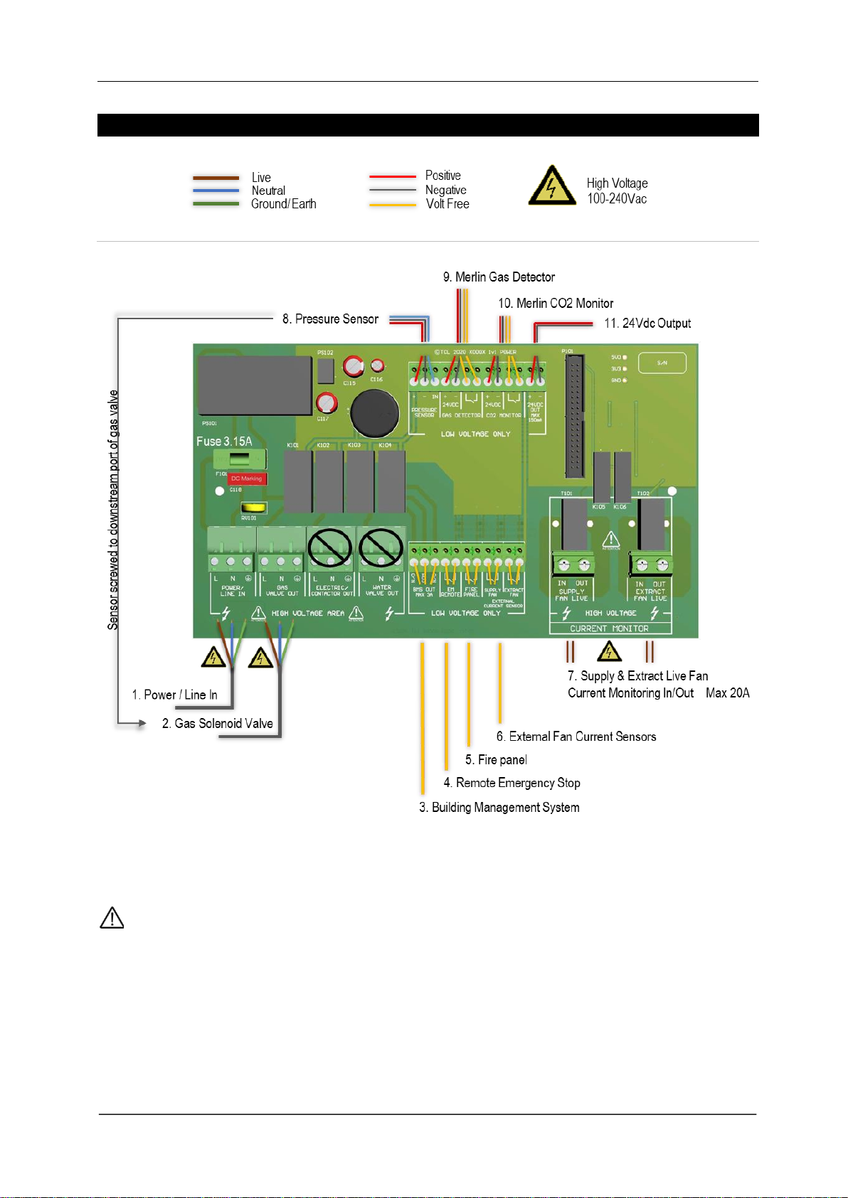
Board Connections Overview
1. POWER / LINE IN.
100-240Vac electrical power should be supplied to the [POWER / LINE IN] terminal and fused at 3A.
On connecting the mains supply to the panel the power LED indicator will light up –this is located
on the front cover (red dot of logo).
2. GAS VALVE OUT.
100-240Vac electrical power output is supplied from the [GAS VALVE OUT] terminal using a 3 core
cable can be connected to a gas solenoid valve and isolate gas supply on alarm status. Pressure
sensors should be screwed to the downstream port of the solenoid valve.
Refer to your valve manual for more information.
3. BMS OUTPUT.
Connections are available on the board for Building Management Systems. This is a relay that
changes state in alarm or when the gas is on/off. It can be used in conjunction with the 24Vdc
output and other external relays that affect other devices and controls such as purge fans and
audible alarms etc.
See section: SETTINGS- for BMS options.
4. EM REMOTE.
Open/Close circuit connections for external devices is marked as [EM STOP] and can shut off utility
supply when activated.
This is fitted with a factory link to represent a closed circuit.
5. FIRE PANEL
The terminal for fire alarms is detailed on the circuit board as [FIRE PANEL] and can shut off utility
supply when activated.
This is fitted with a factory link to represent a closed circuit.
6. EXTERNAL FAN CURRENT SENSORS
These terminals are used to receive an input signal from external air pressure switches or external
current monitors. These are linked out as a factory setting to represent a closed circuit.
If only one fan is being used, the terminal not in use should be left closed!

Installation & Operation Manual Merlin 2000X
Rev: 1 7
7. CURRENT MONITOR
There are two terminals on the circuit board, one detailed as
pictured [SUPPLY FAN LIVE] the other detailed [EXTRACT
FAN LIVE].
The live feed from the fan controller should be connected to
either the supply or extract side depending on which fan/s are
being monitored.
Each will monitor its own independent fan.
From a fan controller the live feed should be taken to the [IN]
terminal and the [OUT] terminal should wire to the fan motor controller.
Max 18A.
8. PRESSURE SENSOR.
The sensor will monitor the gas supply pressure and if pressure
drops below 12mbar –the gas valve will close as this could mean a gas leak is
present.
Operating pressure: 0-100mbar.
Screw the sensor into the downstream port of the gas solenoid valve.
9. GAS DETECTOR.
24Vdc power can be supplied to a Merlin gas detector to shut off the system in the event of
dangerous gas concentrations being detected. If no detector is being used leave the factory fitted
link in.
Refer to your gas detector manual for further information.
10. CO2 MONITOR.
24Vdc power can be supplied to a Merlin CO2monitor to shut off the system if high concentrations
of CO2is detected.
Refer to your CO2monitor manual for further information.
11. 24V DC.
This is a permanent power output for external auxiliary devices when there is power supplied to the
panel and can be used to create a relay switch with the BMS relay output.
Max output: 150mA

Installation & Operation Manual Merlin 2000X
Rev: 1 8
Access Configuration Settings
On the front fascia circuit board you’ll find a [SETTINGS] dip-switch –when switched ON (before turning
the panel on) via the key switch, the screen will display the settings menu –you can now configure your
panel. To view, change and save settings, you must provide mains power.
There are four buttons, press to navigate through the settings and
configure the system. To select functions and change options;
navigate functions by pressing [UP] or [DOWN];
press [OK] to select options;
press [UP] or [DOWN] to change option setting;
press [OK]to save option or [BACK] to return to function.
When changes have been made –turn the SETTINGS switch OFF and restart the key switch!
Configuration Settings Explained
Page 1 Page 2 Page 3 Page 4 Page 5
FUNCTION
OPTION
Explanation
PROVING
- OFF
- ON
Enable/disable gas pressure proving upon system start up/reset to check the
gas line for leaks. See section: LED status.
FILL TIME (S)
- 5
- 10
Time (seconds) the gas valve is open to fill gas line for proving.
Proving must be switched on.
PROVE TIME (S)
- 30
- 50
Time (seconds) the panel tests the gas line for leaks.
Proving must be switched ON.
TOLERANCE (%)
- 10
- 15
Percentage drop in pressure for failure of the gas proving test.
(10% or <12mbar). Proving must be switched ON.
TIMEOUT (H)
- OFF
- 1-12
Time (hours) that the system will automatically shut down all utility supply.
Select OFF or from 1 to 12 hours.
BMS SEL.
- GAS ON
- ERROR
- KEY SW.
GAS ON signals the BMS when gas is supplied or not only.
ERROR signals the BMS on an error condition i.e. gas levels, etc.
KEY SW. BMS follow by key switch ON/OFF status only.
GEW BUTTONS (S)
- 10
- ON
Gas (G) touch buttons on the panel will be active for 10 seconds to enable
supply when key switch is turned ON or be set permanently ON and active
anytime. See section: First Power Up.
FACTORY RESET
- NO
- YES
Return to factory set condition.
See Section: Factory Set Condition
FANS CM.
- OFF
- ON
- SUP ONLY
- EXT ONLY
Combination of fan current monitoring.
Select either current monitoring OFF, current monitoring for both Supply and
Extract (ON) or either Supply or Extract only.
Installation & Operation Manual Merlin 2000X
Rev: 1 9
FANS CALIB.
-
- OK
If fans are calibrated, this will be set as ‘OK’.
See section: Fan Calibration to calibrate fans.
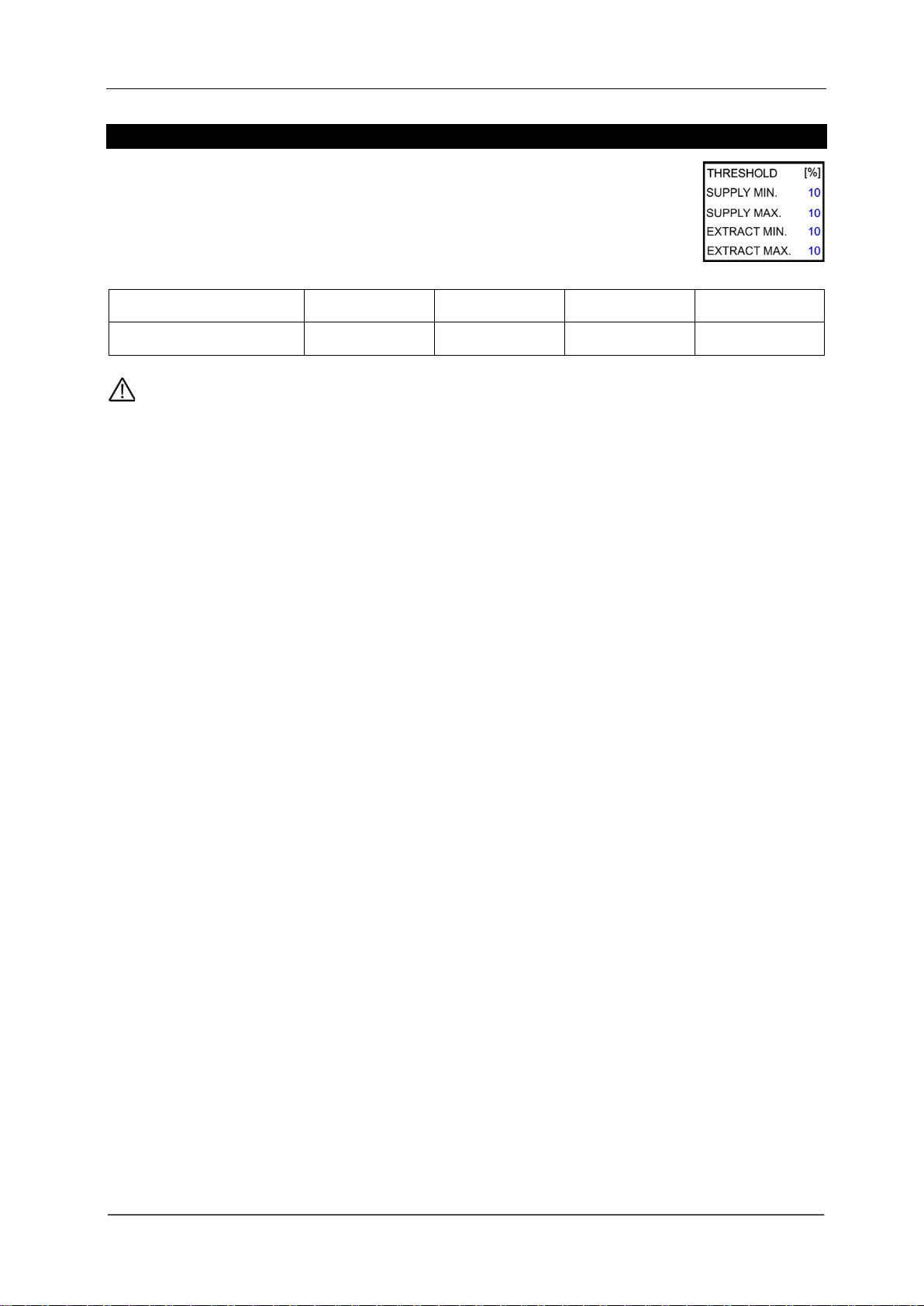
FANS THRESHOLD
%
- 10
- 20
- 30
- 40
Dropout threshold for Min and Max current values of both supply and
extraction fans. It is possible to select between a 10% to a 40% dropout
threshold if required. You will need to recalibrate fans after changing dropout
thresholds. See section: Fan Dropout Threshold Values.
FANS CALIB. RESET
- NO
- YES
Remove and reset any saved fan calibration settings.
See Section: Factory Set Condition
Factory Set Condition
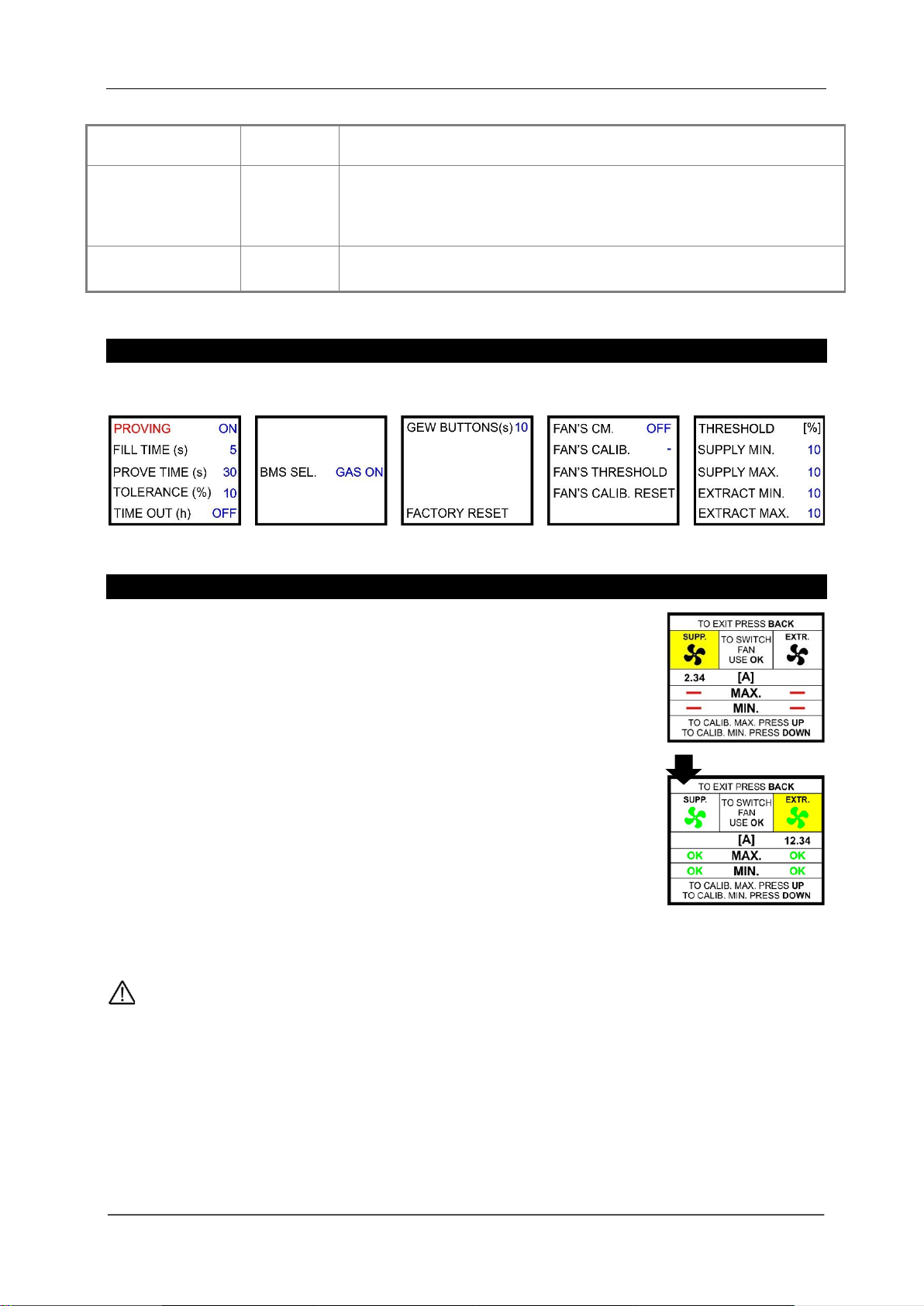
Fan Calibration
Select [FANS CALIB.] In the settings menu.
1. Press [OK] to switch to supply (SUPP.) or extraction (EXTR.) fan.
Fan selection highlighted yellow.
2. Wait for the current value to appear (A).
3. Press [UP] button to calibrate highest fan current.
If successful, ‘OK’appears on screen (MAX.)
4. Press [DOWN] button to calibrate low fan current.
If successful, ‘OK’appears on screen (MIN.)
Fan icons switch from black to green.
If calibration is unsuccessful then alter fan dropout thresholds in the settings menu and repeat.
Installation & Operation Manual Merlin 2000X
Rev: 1 10
Fan Dropout Threshold Values
When [FANS THRESHOLD]is selected in the settings menu, the user can adjust the
minimum and maximum current values by 10, 20, 30 or 40%.
Fans with a current between 0.1 to 0.2A we recommend a dropout threshold ≥30%.
Threshold value (%)
10
20
30
40
Running current (Max.)
18A
16.5A
15A
14A
If calibration is successful it is possible to change the fan threshold without recalibration.
Fans new threshold automatically recalculates min and max current fan fault values.
The 2000X can display fan currents (amp) and gas pressure (mbar) in the diagnostic screen.
See section: Diagnostics

Installation & Operation Manual Merlin 2000X
Rev: 1 11
Specification
Model:
2000X
Display
1.8” Screen TFT (located inside)
Power Input Voltage
100-240Vac
Gas Valve Output Voltage
100-240Vac
BMS Max Output
3A
Single phase AC current monitor calibration range
0.1 –18 Amps
Single phase AC current monitor display
0 - 22Amps
Power Consumption
4.7 W (Panel), 20W max (fully loaded)
Internal Fuse
3.15A
Operating Temperature
0 –50°C (32 –122°F) 30-85%RH Non-Condensing
Audible Alarm Buzzer dB
65 dB (300mm distance in quiet conditions)
Pressure Sensor Operating Pressure
0 - 100mbar
O/All Dimensions (H x W x D) mm
180 x 255 x 77mm

Installation & Operation Manual Merlin 2000X
Rev: 1 12
OPERATION
First Power Up
1. Supply mains power, the red LED on the front of the panel will illuminate (dot on logo).
2. Turn fans on.
3. Turn the key switch to on position.
4. **Gas service LED will flash for 10 seconds.
5. **Press Gas service button to turn gas valve on.
6. **The panel will check the integrity of the gas line for leaks.
**Factory set condition.
Gas service can be turned on or off within 10 seconds of the key switch being on and panel powered up.
After 10 seconds, gas utility button will be disabled. The user must turn the key off and back on to adjust
services. (This can be changed to permanently available in settings).
LED Indication Status
Testing
This LED will illuminate for approximately 30 seconds when the panel is checking the integrity of the
gas installation upon start up. Do not operate appliances while this is on.
Test Fail
Under normal working conditions this LED is off. If the panel detects an issue with the gas supply
upon start-up this LED will illuminate and the gas valve will remain closed.
Pressure Low
Under normal working conditions this LED is off. The LED will illuminate when pressure of the gas
supply drops below 12mbar for 10 secs or more and the gas valve will close.
Timeout
This LED will illuminate if automatic shut-down has occurred following defined timer.
EM Stop
If an emergency shut off button (either remote or on the panel) is pressed, the LED will illuminate
and the gas supply will be isolated. Any shut-off buttons must be reset before restarting the system.
Gas Detected
If an external Merlin detector connected detects dangerous gas levels this LED will illuminate and
the gas supply is isolated.
Installation & Operation Manual Merlin 2000X
Rev: 1 13
CO2High
If the concentration of CO2 in the air is at alarm level (relevant detector required), the LED will
illuminate and the gas supply is isolated.
Fire Alarm
If the fire panel connected detects a fire the LED will illuminate and the gas is isolated.
Supply Fan - Under normal working conditions this LED is on.
If a supply fan external current sensor fault is detected, the LED will flash.
After ~20 seconds: the LED will remain on and Fan Fault LED will illuminate.
If a supply fan internal current monitor fault is detected, the LED will flash.
After ~20 seconds the LED will flash twice a second and Fan Fault LED will illuminate.
Extract Fan - Under normal working conditions this LED is on.
If an extract fan external current sensor fault is detected, the LED will flash.
After ~20 seconds: the LED will remain on and Fan Fault LED will illuminate.
If an extract fan internal current monitor fault is detected, the LED will flash.
After ~20 seconds the LED will flash twice a second and Fan Fault LED will illuminate.
Fan Fault
If a fan fault occurs for longer than 20 seconds, the LED will illuminate RED.
Utility Touch Buttons / LED Indication Status
Gas - When the key switch is turned on, the system will check the installation for gas leaks.
**If gas proving is successful, the Testing LED will turn off and this Gas LED will remain ON.
**Factory Set Condition.
Gas LED will flash when checking external current sensors, current monitor or gas proving.
Installation & Operation Manual Merlin 2000X
Rev: 1 14
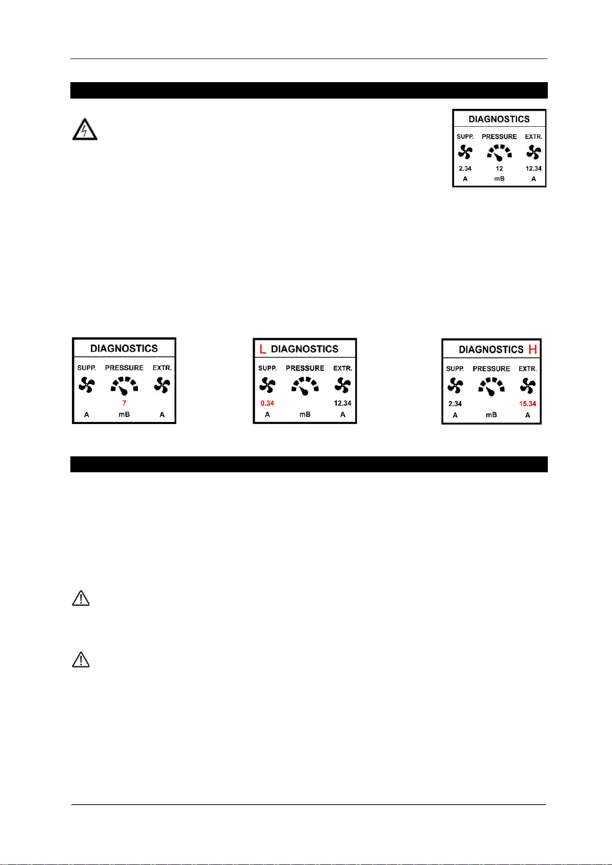
System Diagnostics
WARNING! Contact with mains electrical power can be fatal!
The panel can display fan current (Amps) and gas pressure (mbar).
To view these diagnostics, carefully remove the front fascia of the panel, to activate screen diagnostics,
press either the [OK], [UP] or [DOWN] button. The diagnostic screen is available during; proving status;
normal operation; fan fault and pressure low status. The screen will automatically enter sleep mode after
10 minutes of inactivity or when the [BACK] button pressed.
L= fan current is less than the minimum calibrated value.
H= fan current is greater than the maximum calibrated value.
Gas pressure is low Current higher than calibrated value.
Current less than calibrated value.
General Maintenance
Keep your system in good working order follow these basic principles;
Remove any dust/debris from the outer enclosure regularly using a slightly damp cloth.
Never use detergents or solvents to clean your gas detection devices.
Never spray air fresheners, hair spray, paint or other aerosols near devices.
Never paint devices. Paint will seal vents and interfere with the device.
It is recommended that detectors are inspected and serviced at least annually from the date of
installation for optimum performance and protection due to sensitivity drifts!
High concentrations of alcohol found in many products may damage, deteriorate or affect the gas sensor
such as; wine; deodorants; stain removers; thinners etc. Other gases and substances to avoid are;
Corrosives (i.e. chlorine & hydrogen chloride); Alkali metals; Basic or acidic compounds; Silicones;
Tetraethyl lead; Halogens and halogenated compounds!

Installation & Operation Manual Merlin 2000X
Rev: 1 15
ENGINEERING NOTES - Blank
Installation & Operation Manual Merlin 2000X
Rev: 1 16
Installation Details
Please pass this manual to the system owner or system user.
Date of Installation:
Installation Location:
Organisation:
Stamp/ Signature of the installer:
S&S Northern Head Office
Tel: +44(0) 1257 470 983
Fax: +44(0) 1257 471 937
www.snsnorthern.com
info@snsnorthern.com
South East Division
Tel: +44(0) 1702 291 725
Fax: +44(0) 1702 299 148
S&S Northern is the owner of this document and reserves all rights of modification without prior notice.
Table of contents
Other S&S Northern Control Panel manuals


Popular Control Panel manuals by other brands

Plum
Plum eSTER x80 Installation and operating manual

TUYA
TUYA S9E manual

Genie
Genie Series II installation instructions

Menvier Security
Menvier Security TS700 Installation & programming instructions

Schenck process
Schenck process Intecont Tersus Beltweigher instruction manual

Aritech
Aritech 1X-E4 Series installation manual


