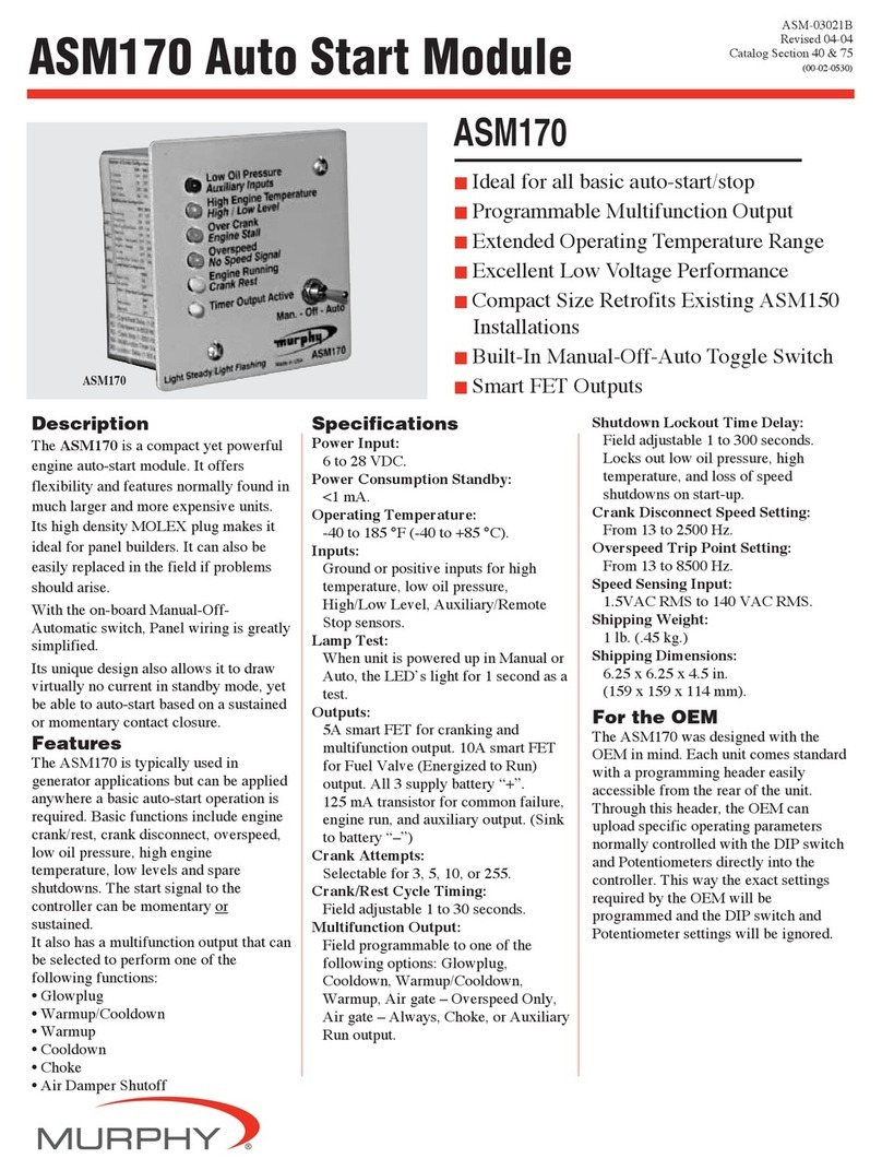
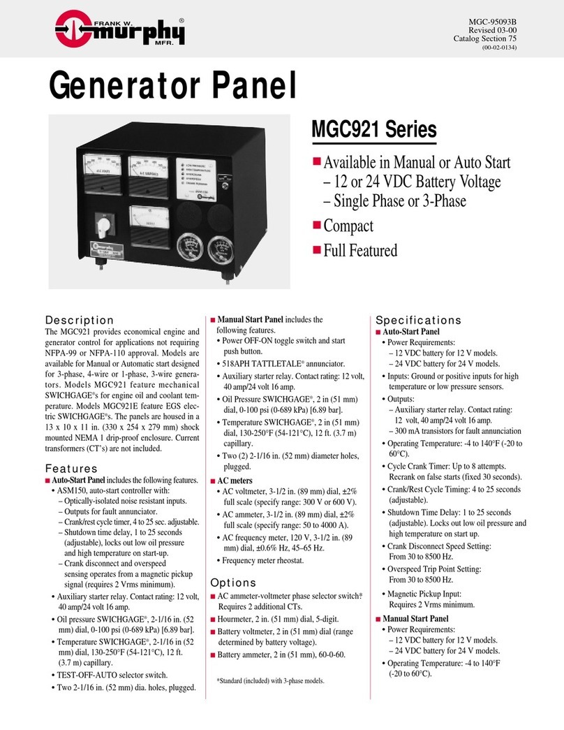
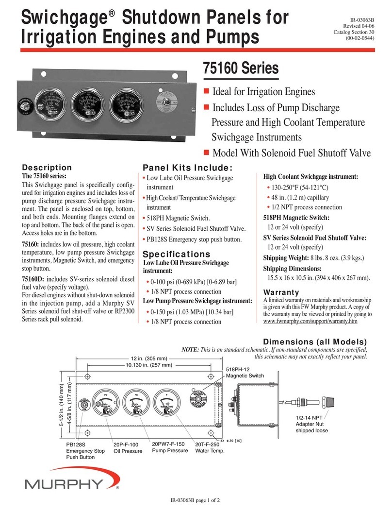
Murphy ML2000 User manual

00-02-0994
2016-06-28
Section 40
Installation and Operations Manual

In order to consistently bring you the highest quality, full-featured products, we reserve the right to change our
specifications and designs at any time.
ENOVATION CONTROLS has made efforts to ensure the reliability of the ML2000
and to recommend safe use practices in system applications. Please note that in any
application, operation and controller failures can occur. These failures might result in
full control outputs or other outputs that might cause damage to or unsafe conditions
in the equipment or process connected to the ML2000.
Good engineering practices, electrical codes and insurance regulations require that
you use independent external protective ML2000 can fail with outputs full ON, outputs
full OFF or that other unexpected conditions can occur.
BEFORE BEGINNING INSTALLATION OF THIS MURPHY
PRODUCT:
•A visual inspection of this product before installation for any damage during
shipping is recommended.
•Disconnect all electrical power to the machine. Failure to disconnect all electrical
power connections before welding can result in damage to the panel and/or its
components.
•It is your responsibility to have a qualified technician install the unit and make sure
installation confirms with local codes.
•Observe all Warnings and Cautions in each section of these instructions.
•The ML2000 is designed for use in industrial environments. There might be
potential difficulties in ensuring electromagnetic compatibility in other
environments due to conducted as well as radiated disturbances.
•Please contact ENOVATION CONTROLS immediately if you have any questions.
IMPORTANT! False or improper use and operation of electronic
products could be dangerous. It is required that point-of-
operation guarding devices be installed and maintained. All such
devices must meet OSHA and ANSI Machine safety standards.
The manufacturer shall not accept any responsibility for
installation, application or safety of systems.

Section 40 00-02-0994
2016-06-28 - iii -
The ML2000 can be set as an AutoStart Controller. Please be cognizant at all times of hands
and other objects that are in close proximity to the machine(s) being controlled as they may
commence operation suddenly and without warning.
LENS CLEANING PROCEDURES
The lens on the display is composed of polycarbonate materials. Use only mild soap and water
to clean the lens/display window. Evidence of improper cleaning techniques or chemicals
includes cracks, smear marks, scratches or fogged/hazy lenses.

Section 40 00-02-0994
2016-06-28 - iv -
- THIS PAGE INTENTIONALLY LEFT BLANK -

Section 40 00-02-0994
2016-06-28 - v -
Table of Contents
Introduction.................................................................................................................................7
Mounting the Unit .........................................................................................................7
Wiring...........................................................................................................................9
Murphy PowerCore®20 (MPC-20) .............................................................................11
User Interface.............................................................................................................13
Accessing the Menu ................................................................................................................14
Main Menu .................................................................................................................................15
Start/Stop Settings...................................................................................................................19
Single Contact Start/Stop...........................................................................................19
Two Contact Maintained Start/Stop (commonly known as Floats) .............................19
Two Contact Momentary Start/Stop ...........................................................................19
(Level, Pressure, Temperature or Flow) Transducer Start/Stop.................................19
Local Start Key Start/Stop..........................................................................................19
Quick-Start Setup Guide .........................................................................................................20
Adjusting the Contrast................................................................................................20
Setting MPC-20 to Auto Start on a Single Contact Input............................................20
Setting MPC-20 to Auto Start on Local Key ...............................................................20
Setting MPC-20 to Auto Start on Float Inputs ............................................................20
Setting MPC-20 to Auto Start on Pressure.................................................................21
Setting MPC-20 to Auto Start on Level ......................................................................21
Setting MPC-20 to Auto Start on Flow .......................................................................21
Setting MPC-20 to Auto Start on Clock ......................................................................21
Setting MPC-20 to Auto Start on Temperature...........................................................21
Setting MPC-20 to Stop the Engine from Utilizing the Countdown Timer...................22
Screen Examples .....................................................................................................................22
MPC-20 Screens In Order..........................................................................................23
Warning and Shut-Down Icons...................................................................................27
Icon Troubleshooting..................................................................................................27
Menu Glossary .........................................................................................................................28
Section 40 00-02-0994
2016-06-28 - vi -
System .......................................................................................................................28
Engine Settings ..........................................................................................................29
Advanced Engine Settings .........................................................................................30
Throttle Menu .............................................................................................................33
Input / Output Menu ...................................................................................................33
Application Configuration ...........................................................................................37
Start / Stop Timers .....................................................................................................39
Communication ..........................................................................................................40
Modbus Registers ......................................................................................................40
Specifications ...........................................................................................................................46
Electrical.....................................................................................................................46
Environmental ............................................................................................................46
Mechanical.................................................................................................................46

Section 40 00-02-0994
2016-06-28 - 7 -
Introduction
The Murphy Ready to Run family offers users a wide range of control and monitoring solutions for Isuzu
engines. The Ready to Run Panel kits allow for a number of mounting configurations. The panels come
ready, right out of the box for a quick and easy installation.
The ML2000 Panel using the MPC-20 Display is configurable from the controller. The features include an
additional shutdown using the included I/O, an advanced auto start solution and RPM set points
adjustable from the display. An optional I/O harness is available. The MPC-20 can be mounted either
from the front or fully enclosed within the panel.
Your kit contains a control box, protected ECU mount and engine harness. With an installation time of
less than 10 minutes, it makes sense to run your new engine with a Murphy solution.
Mounting Dimensions

Section 40 00-02-0994
2016-06-28 - 8 -
ECU Mounting (4JJ1T and 4LE2)
Accessories
Description
Part Number
I/O Whip Harness for ML2000 panel
(10’ long, 31-position connector)
40000618
I/O Connector Kit (31-position connector)
78700046

Section 40 00-02-0994
2016-06-28 - 9 -
Wiring
4JJ1T Harness

Section 40 00-02-0994
2016-06-28 - 10 -
4LE2 Harness

Section 40 00-02-0994
2016-06-28 - 11 -
Murphy PowerCore®20 (MPC-20)
The Murphy PowerCore 20 Controller (MPC-20) is a general all-purpose manual/auto start and manual/auto
throttling engine controller. The controller is purposed primarily for pump and irrigation applications. However, it is
versatile and flexible enough to be used on many applications outside pump and irrigation. This is a powerful
controller that supports J1939 CAN protocols for electronically governed engines as well as mechanical engines for
fault and safety shutdowns.
The MPC-20 is flexible in many aspects and consists of the ability to:
•use in most applications where auto start or auto throttling is required or desired;
•use the same controller on electronically governed J1939 and mechanical engines;
•use the same controller on 12VDC or 24VDC systems;
•use as auto start or manual start controller;
•use as manual throttle or auto throttle controller;
•change the input type for the analog inputs;
•use additional analog inputs as digital ground inputs;
•assign functions and actions to digital inputs;
•use digital inputs as battery or ground inputs;
•be mounted in all-weather environment;
•be customer-mounted in panel of choice.
Engine Application States
The MPC-20 Controller, while reprogrammable, follows a standard operating sequence. This operating sequence
is a set of machine states that happen in a predetermined order. Machine states can be set to zero if not needed
or adjusted to fit the application. The following states will be executed during the auto sequence, provided that
the corresponding timer has not been set to 00:00:00 or the controller has not been placed in a manual mode of
operation:
•Stabilize: This is a timed state to allow the controller to enable the ECU or any senders without
warnings or errors. This timer can be disabled if set up for mechanical engine use.
•Stopped: This is a timed state where the engine is ready to be started manually or automatically.
•Standby: This is a timed state that will shut off the LCD backlight, heater and CAN transceiver to
conserve power while the unit waits for a key press or an automatic start condition.
•Auto Start Delay: (available in Auto mode only) The auto start condition is ignored and must
remain active throughout this delay, or the delay is reset to zero.
•Check Safe To Start: This is a non-timed state that will check to ensure the engine can start
safely.
•Auto Stop Delay: (available in Auto Mode only) The auto stop condition is ignored and must
remain active throughout this delay, or the delay is reset to zero.
•Minimum Run Time: This timer is only active using auto start and with all auto start types except
local key and clock. Local stop key will also initiate the stop sequence before the timer expires, if
pressed.
•ECU Stabilize Timer: This delay begins timing when the controller is powered up, Spindown or
Standby delays have expired. During this delay, the ECU enable output is turned on. The ECU
output turns off when the Standby, ETS or Spindown delays begin timing.
•Prestart Delay 1: (available in Auto Mode only) After an auto start condition has been accepted
by the controller, this delay begins timing, and the prestart output turns on. When this delay
expires, the output is turned off, and the auto sequence continues.
•*Prestart Delay 2 (precrank): (available in Auto Mode only) After an auto start condition has
been accepted by the controller, this delay begins timing, and the prestart output turns on. When
this delay expires, the output is turned off, and the auto sequence continues. During this delay,
the controller checks for faults, J1939 com, etc.

Section 40 00-02-0994
2016-06-28 - 12 -
•*Prestart Delay 2 (crank through): (available in Auto Mode only) After an auto start condition
has been accepted by the controller, this delay begins timing, and the prestart output turns on.
When this delay expires, the output remains on, and the auto sequence continues. The output
turns off when the engine actually starts. During this delay, the controller checks for faults, J1939
com, etc.
•Crank: This is a timed state to try and start the engine.
•Crank Rest: This is a timed state to rest the starter between cranks in case the engine did not
start during the crank state.
•False Start Check: This is a non-timed state that will ensure the engine stays above the crank cut
RPM after cranking.
•Warm-up: (available in Auto mode only) This is a timed state that will allow the engine to
change from idle to desired warm-up RPM after starting. Warm-up will only set as low as the
minimum RPM set point.
•Line Fill 1: (available in Auto mode only) This is a timed state that will exit if the timer times out
or the pressure set point for this state is reached.
•Line Fill 2: (available in Auto mode only) This is a timed state that will exit if the timer times out
or the pressure set point for this state is reached.
•Running Loaded: This is a non-timed state that the controller will stay in until a stop condition
occurs.
•Cool-down: (available in Auto mode only) This is a timed state that will allow the engine to run
at a desired speed to cool down before allowing to go into a stopped state.
•Energize to Stop: This is a timed state that will control an output in order to stop the engine.
•Spindown:The time allotted for the engine to stop all revolutions and be in a stopped state with
no frequency.
•Post Crank Lockout Delay (setup): This delay begins timing when the engine actually starts.
During this delay, the selected function is ignored. When this delay expires, the selected function
is armed. During the duration of this delay, the selected function can cycle from active to not
active and not reset the delay.
•Post Warm-up Lockout Delay (setup): This delay begins timing when the warm-up delay expires.
During this delay, the selected function is ignored. When this delay expires, the selected function
is armed. During the duration of this delay, the selected function can cycle from active to not
active and not reset the delay.
•Bubble Lockout Delay (setup): This delay begins timing when the selected function is active. If the
selected function is removed during this delay, the delay resets to zero. If the selected function
remains active throughout this delay, the selected action will occur.

Section 40 00-02-0994
2016-06-28 - 13 -
User Interface
The keypad on the MPC-20 is comprised of 11 tactile buttons. This section describes the functions of each
button.
The buttons have the following functions:
•Start Key – Allows the operator to start sequence in Manual Mode or initiate an auto start
sequence when in Auto Mode.
•Stop Key – Allows the operator to initiate the stop sequence in either mode of operation. A
single button press in auto will initiate an auto stop. As a safety feature, when the stop button
is pressed twice or held (in auto mode), the controller will skip the cool-down state and (upon
shutting down) will place itself in manual mode to eliminate an auto crank condition. This
happens if the autostart condition is still present.
•Auto Key – Allows the operator to change from Auto to Manual or Manual to Auto Mode by
press-hold for 3 seconds.
•Alarm Silence Key – Allows the operator to silence the internal siren when an alarm or
shutdown is present on the controller.
•Manual Throttle Increase Key – Allows the operator to manually increase the engine throttle
in Manual Mode.
•Manual Throttle Decrease Key – Allows the operator to manually decrease the engine throttle
in Manual Mode.
•Menu Key – Allows the operator to get into and out of the menus.
•Back Key – Allows the operator to move back one step while in the menu.
•Enter Key – Allows the operator to enter a value in the menu when selected and is used to
acknowledge internal and external alarm/shutdowns.
•Up Key – Allows the operator to navigate up through the menu and page forward on the main
pages.

Section 40 00-02-0994
2016-06-28 - 14 -
•Down Key – Allows the operator to navigate down through the menu and page reverse on the
main pages.
Accessing the Menu
To access the MPC-20 menu, press the menu button:
The following screen will display to enter the password (3482):
The password will be entered left to right. Utilize the up and down arrows, and press the Enter button after each
correct number: . Entering this password will allow full access to the menu. If you enter the wrong
password, it will reset the display to 0000, allowing you to restart the entering process.

Section 40 00-02-0994
2016-06-28 - 15 -
Main Menu
The MPC-20 controller is incredibly versatile within the menu structure. The operator is able to change many
parameters and settings from the face without the need of a PC tool, if desired. The controller has to be in its
stopped state in order to change a setting in the menu. (The Tier 4 menu is the exception.) Described below are
the main sections of the controller’s menu. Cycling power to the controller is recommended after making
changes to set points.
(Main Menu, page 1)
System
The controller System menu provides the operator with the ability to set the Date/Time, Units, Language,
Brightness, Contrast, Service Reminders and several other system settings. Review System under the Menu
Glossary section of this manual for a full list and definition of each setting.
Engine Settings
The Engine Settings menu allows the operator to establish common, user-configurable parameters that would be
changed from factory-default settings when pairing the controller to an engine. This menu allows the operator to
choose whether the engine is J1939 or mechanical; the engine’s speed source; the minimum and maximum RPM
the operator requires/allows the engine to run; the RPM step size; warm-up/cool-down settings; and other common
engine settings. Review Engine Settings under the Menu Glossary section of this manual for a full list and definition
of each setting.
Advanced Engine Settings
The Advanced Engine Settings menu allows the operator to set up the less common user-configurable parameters
that are not in the Engine Settings menu and which would be changed from factory-default settings when pairing
the controller to an engine. This menu allows the operator to set items such as the J1939 address claim for the
controller, ECU Source Address, ECU hour select, crank attempts, crank disconnect speed, clutch
engage/disengage speed, run to destruct mode and other user-specific engine settings. Review Advanced Engine
Settings under the Menu Glossary section of this manual for a full list and definition of each setting.

Section 40 00-02-0994
2016-06-28 - 16 -
Throttle
The Throttle menu allows the operator to set up the items for throttling the engine such as throttle type, rate of RPM
increase/decrease, throttle Inc/Dec pulse time, throttle RPM deadband and other parameters pertaining to throttling
of the engine. Review Throttle under the Menu Glossary section of this manual for a full list and definition of each
setting.
Input / Output
The Input/Output Menu allows the user to establish the I/O needed for the application. This includes Digital Inputs,
Analog Inputs, Relay Outputs and Digital Outputs. This menu is tied to other aspects of the controller menu such
as Auto Start Functions, Auto Throttling Methods, Analog inputs for Mechanical Engine setup, Warning / Shutdown
functions and all outputs needed for starting/controlling the engine and alerting the user.
The Digital Inputs of this menu can be configured from the face of the controller to accept three types of inputs.
•High, B(+)
•Low, B(-)
•Open
The Analog Inputs of this menu can be configured from the face of the controller to accept one of four types of
senders without having to order a new controller or arrange jumpers on the hardware.
•Resistive
•4-20mA
•0-5VDC
•B(-) for additional Digital Inputs
The Outputs are configurable for the operator to choose which output function to use with the desired output
type as shown below.
•Relay [10A, Form C]
•Digital Out [200mA, 5VDC]
•Digital Out [2A, B(+)]
•Digital Out [1A, B(-)]
NOTE: Although the functionality exists to set all analog and digital inputs to the same
function, Enovation Controls strongly advises against this.
(Main Menu, page 2)

Section 40 00-02-0994
2016-06-28 - 17 -
Application Configuration
The Application Configuration menu is where an operator will set up the controller’s Auto Start Functions and Auto
Throttle Methods, if the intended use is as an auto start and/or auto throttling controller. Depending on which
application is chosen in the menu, there are certain auto start functions and auto throttling methods hidden that are
not pertinent to the application chosen. This automatic hiding feature allows for a simpler, more intuitive controller
menu in the MPC-20. Review Application Configuration under the Menu Glossary section of this manual for the full
list and definition of each setting.
Pump All Purpose
The Pump All Purpose application houses most all auto start functions and auto throttling methods of the
controller. This application is the most versatile application thus requiring so many combinations of settings
for the operator to choose.
The auto start functions and auto throttle methods to choose from are listed below.
Auto Start/Stop Functions
•Level Transducer (will require an Analog Input Setting)
•Flow Transducer (will require an Analog Input Setting)
•Single Contact
•Local Key Start
•Two Contact Maintained
•Two Contact Momentary
•Pressure Transducer (will require an analog input setting)
Auto Throttle Methods
•Maximum RPM
•Pressure Transducer
•Level Transducer
•Flow Transducer
•Local Throttle Input (this feature throttles the engine proportionally between the minimum and
maximum RPM set points)
Center Pivot / Linear Irrigation
The Center Pivot / Linear Irrigation application houses the auto start functions and auto throttle methods
meant to be used on center pivot and linear movement irrigation applications.
The auto start functions and auto throttle methods to choose from are listed below.
Auto Start/Stop Functions
•Single Contact (will require a digital input for start and stop)
•Local Start Key
•Two Contact Maintained (will require a digital input for start and stop)
•Two Contact Momentary (will require a digital input for start and stop)
Auto Throttle Methods
•Maximum RPM
•Pressure Transducer (will require an analog input)
•Flow Transducer (will require an analog input)
•Local Throttle Input
Air Compressor
The Air Compressor application houses the auto start functions and auto throttle methods meant to be used
on all engine-driven air compressor applications. The MPC-20 allows for the compressor to start/stop and
maintain a desired pressure during operation.

Section 40 00-02-0994
2016-06-28 - 18 -
The auto start functions and auto throttle methods to choose from are listed below.
Auto Start/Stop Functions
•Single Contact (will require a digital input for start and stop)
•Two Contact Maintained (will require a digital input for start and stop)
•Two Contact Momentary (will require a digital input for start and stop)
•Pressure Transducer (will require an analog input)
Auto Throttle Methods
•Maximum RPM
•Pressure Transducer (will require an analog input)
•Local Throttle Input
Hose Reel Irrigation
The Hose Reel Irrigation application houses the auto start functions and auto throttle methods meant to be
used on hose reel irrigation systems. The MPC-20 allows for the hose reel pump to auto start with several
methods, including the Local Key Start which may be the most used in this application. The key feature of
this application is the auto throttling method. This feature allows the controller to manage the pump’s throttle
in order to maintain a pressure in the hose during irrigation.
The auto start functions and auto throttle methods to choose from are listed below.
Auto Start/Stop Functions
•Single Contact (will require a digital input for start and stop)
•Local Start Key
•Two Contact Maintained (will require digital inputs for start and stop)
•Two Contact Momentary (will require digital inputs for start and stop)
Auto Throttle Methods
•Maximum RPM
•Pressure Transducer (will require an analog input)
•Local Throttle Input
Frost Protection
The Frost Protection application houses the auto start functions and auto throttle methods meant to be used
on frost protection systems. This application allows for wind machine, sprinkler or other forms of frost
protection using single contact or a temperature transducer.
The auto start functions and auto throttle methods to choose from are listed below.
Auto Start/Stop Functions
•Single Contact (will require a digital input for start and stop)
•Temperature Transducer (will require an analog input for start and stop)
Auto Throttle Methods
•Maximum RPM
Start / Stop Timers
The Start/Stop Timers menu provides the operator the ability to add a countdown timer and start/stop times. The
countdown timer allows for the operator to set a desired countdown time and walk away from the engine for a
controlled shutdown when the timer expires. There are eight Start/Stop Timers the operator can choose from within
this menu that allows for the specific day and hour the controller will start and stop utilizing the internal clock. Review
Start/Stop Timers under Menu Glossary section of this manual for full list and definition of each setting.
Start / Stop timers work in conjunction with other Start / Stop types. If the engine is already running from another
Start / Stop type when a Start / Stop timer occurs, the Start / Stop timer is ignored. Once the engine is started by
the Start / Stop timer, the timer has to expire for a controlled shutdown to occur.

Section 40 00-02-0994
2016-06-28 - 19 -
Communication
The Communications menu allows the operator to choose the type of RS485 communications such as PVA Gauge,
Modbus or Local Display. The menu also allows for the operator to choose the RS485 slave address, RS485 Serial
setup and whether or not the controller uses the internal CAN terminating resistor. Review Communication under
the Menu Glossary section of this manual for a full list and definition of each setting.
Start/Stop Settings
There are eight automatic start/stop types in the MPC-20. Each is detailed below:
Single Contact Start/Stop
The Single Contact Start/Stop is when a remote contact closes and remains closed for auto start and re-opens for
auto stop.
Two Contact Maintained Start/Stop (commonly known as Floats)
The Two Contact Maintained Start/Stop is when both contacts close for auto start and both contacts open for auto
stop (not momentarily). This may also be reversed by altering menu settings.
Two Contact Momentary Start/Stop
The Two Contact Momentary Start/Stop is when one contact closes momentarily for start and another contact
closes momentarily for stop.
(Level, Pressure, Temperature or Flow) Transducer Start/Stop
A transducer is used for auto throttling and start/stop. There are set points allowing the operator to enter the
appropriate values.
Local Start Key Start/Stop
The Local Start Key Start/Stop is used to remove any other auto start/stop types within the controller if they are
not needed, regardless if in auto or manual modes.
If an auto stop condition occurs during the warm-up delay, the controller will enter an auto stop sequence.

Section 40 00-02-0994
2016-06-28 - 20 -
Quick-Start Setup Guide
The following sections serve to provide a walk-through of the steps necessary for some of the various
configurations and settings available on the MPC-20 Controller. Cycling power to the controller is
recommended after making changes to set points.
Stepping through the Menu will be depicted as follows:
Menu/System/Contrast directs the operator to go into the Menu first, then look for a parameter titled System and
press [Enter] to go into the System menu. Then look for a parameter titled Contrast and press [Enter] to go into
the Contrast menu, etc.
Adjusting the Contrast
1. Access Menu/System/Contrast.
2. Utilize the Up and Down arrows to adjust the Contrast (values of 0 to 255), and press [Enter] when the
desired number appears.
3. Press the [Menu] key to leave the Menu Setup screens.
NOTE: The following parameters all utilize the Application Configuration of Pump All
Purpose.The MPC-20 will hide or display certain parameters that are specific to the
Application Configuration chosen.
Setting MPC-20 to Auto Start on a Single Contact Input
1. Access Menu/Application Configuration/Auto Start_Stop Function/Single Contact.
2. Press [Back]once and select Input / Output/Digital Inputs.
3. Assign the Function of Single Contact Start/Stop to one of the Digital Inputs.
4. Press the [Menu] key to leave the Menu Setup screens.
Setting MPC-20 to Auto Start on Local Key
1. Access Menu/Application Configuration/Auto Start_Stop Function/Local Start Key and press [Enter].
2. Press the [Menu] key to leave the Menu Setup screens.
Setting MPC-20 to Auto Start on Float Inputs
1. Access Menu/Application Configuration/Auto Start_Stop Function.
2. Highlight Single Contact, Two Contact Maintained or Two Contact Momentary and press [Enter].
3. Press [Back]once and access Input / Output/Digital Inputs, and select a Digital Input to modify.
4. Assign the appropriate input for the selected AI.
NOTE: If Single Contact is chosen, only one digital input needs to be configured. If Two
Contact (Maintained and Momentary) is chosen, two digital inputs need to be configured, one
for start and one for stop.
5. Ensure the appropriate number of Digital Inputs is configured (as per the Note above), and press the
[Menu] key to leave the Menu Setup screens.
Table of contents
Other Murphy Control Panel manuals

Murphy
Murphy Swichgage Shutdown Panels 75160 Series User manual

Murphy
Murphy Auto Start Module ASM170 User manual

Murphy
Murphy Selectronic Tattletale Annunciator ST8 User manual

Murphy
Murphy PowerCore MPC-20 User manual

Murphy
Murphy Digital Generator Panels MGC447 User manual

Murphy
Murphy Generator Panel MGC921 Series User manual

Murphy
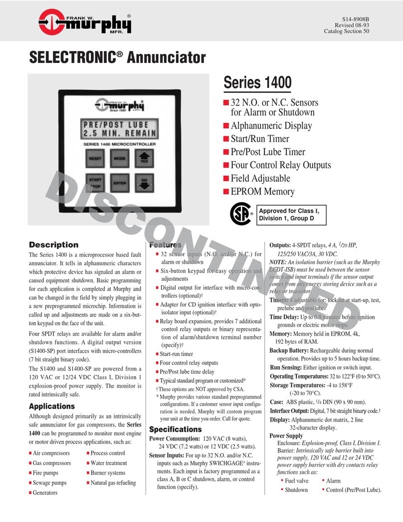
Murphy Selectronic Annunciator Series 1400 User manual

Murphy
Murphy Display and Diagnostic Module MDDM User manual

Murphy
Murphy iGUARD Installation guide