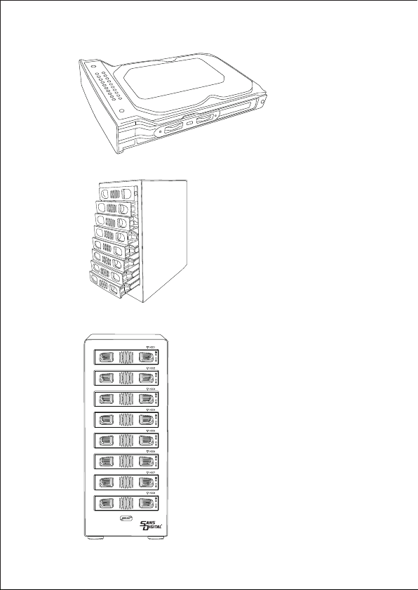
Sans Digital MobileRAID MR8UT6G User manual

- 1 -

Content
1. Features 3
1.1 Overview 3
1.2 SATA features 3
1.3 USB features 3
4
4
4
4
5. Package contents 5
5
6
7
7
7
7
8
8
8
9-10
10-11
12-13
14
15
15
16
17-18
2. Specifications
3. System requirements
4. The device at a glance
4.1 Overview
6. Getting started
6.1 HDD installation
6.2 Power on/off
7. Configuration
7.1 Preparation
7.2 Changing the host connection
7.3 Disconnecting an USB device
7.4 HDD HotPlug
8. Setting the RAID mode
8.1 NORMAL mode
8.2 Other RAID modes
9. Rebuilding a redundant drive
10. Troubleshooting
11. Appendix
11.1 LARGE mode
11.2 R00 mode
11.3 R50 mode
- 2 -

- 3 -
1. Features
1.1 Overview
• External RAID case with eight bays for 2.5" and 3.5" SATA HDDs
• Support RAID Modes: RAID 00, RAID 0 x2, Spanning (Big), Spanning x2, RAID 5 x2,
RAID 50, JBOD (Clean, individual drive mode)
• External interfaces: eSATA and USB3.0
• Aluminum enclosure provide excellent cooling
• Hot swappable trays for easy trouble-shooting
• LED indications for power, HDD activity and rebuild
• Port Multiplier Functionality
• Auto-negotiation between SATA I (1.5 Gbps), SATA II (3 Gbps) and SATA III (6 Gbps)
• Hot-Swap support in CLEAN mode
• Supports Native Command Queue (NCQ)
• Supports Port Multiplier Aware and non-Port Multiplier Aware Host in RAID mode
• Supports Spread Spectrum Clocking
• Supports BIST and Loopback Mode
• Supports 48-bit LBA addressing
• Compatible with USB Super Speed, High Speed and Full Speed
• Compatible with OHCI/UHCI/EHCI hosts
• Supports Mass Storage Class
1.3 USB features
1.2 SATA features

- 4 -
2. Specifications
3. System requirements
4. The device at a glance
4.1 Overview
• Windows 2000/ Me/ XP /Vista/ 7/ 8/ 8.1/10 above, Mac OS 9.1/10. above
Front Panel Rear view
70mm fan
USB3.0 Port
Power
Power connector
Reset button
eSATA Port
RAID mode switches
LED light(Blue)
LED light(Red)
HDD 1
HDD 2
HDD 3
HDD 4
HDD 5
HDD 6
HDD 7
HDD 8
• Tool free installation
Tool less installation for 3.5 inch Hard Drive.
• Plug and Play
Supports standard 2.5/3.5 inch SATA HDDs and SSDs.
•High Speed data transfer
USB 3.0 or eSATA Connectivity
• Aluminum Case
High-quality aluminum material with good heat dissipation
• Quiet cooling fan
Low speed cooling fan delivers highly efficient cooling
• RAID Level
Support RAID 0 / RAID 0 x2/ RAID 50/ RAID 5 x2/ Spanning /
Spanning x2 / JBOD

- 5 -
5. Package contents
6. Getting started
Fig.2
• 8 bay MR8UT6G RAID Enclosure
• USB 3.0 Cable ; eSATA Cable
• Mounting screws and driver
• Power Cable
• User Manual
1. Unlock the HDD trays lock and remove the HDD trays from
the 8-BAY RAID Enclosure (Fig.1).
6.1 HDD installation
2. Place the HDD into the HDD trays (Fig. 2).
Fig.1

- 6 -
Fig.3
3. Use the mounting screws to securely attach the HDD to the trays (Fig. 3).
4. Slide the HDD trays back into the 8-BAY RAID Enclosure (Fig. 4).
5. Slide the hard drive tray back into the slot to complete the HDD installation (Fig.5)
Fig.4
Fig.5

- 7 -
6.2 Power on/off
Press the power button to switch on the device. Press again to power it off.
On/off button
7. Configuration
7.1 Preparation
1. eSATA host connection
Note:
This installation guide assumes that you have already connected the 8-BAY RAID
Enclosure to a SATA or eSATA host controller with Port Multiplier (PM) support.
2. USB host connection
If you are connecting your 8-BAY RAID Enclosure using an USB connection to your host,
the USB port should be compliant with USB2.0 or 3.0.
If you use a host controller that does not provide Port Multiplier support (Such as Intel
ICH), the CLEAN / JBOD mode will not work properly. Only one disk is available on the
host computer.
7.2 Changing the host connection
The 8-BAY RAID Enclosure supports both USB and eSATA host connections, but only
one connection can be connected at the same time.
To switch from one connection to the other, the host computer and the 8-BAY RAID
Enclosure should both be powered down prior to changing the host connection in order
to avoid data loss. Power off the computer system first before power off the 8-BAY RAID
Enclosure. When power on, power on the RAID Enclosure first before the computer
system.

- 8 -
7.3 Disconnecting an USB device
7.4 HDD Hot Plug
8. Setting the RAID mode
Notes :
USB 3.0 external devices provide support for Plug and Play connection so that
the 8-BAY RAID Enclosure can be connected and disconnected while the
computer is running. To prevent data loss or other failures, we recommend the
following procedures when disconnecting your USB 3.0 from your host comput-
er system:
Before you shut down your PC remove the 8-BAY RAID Enclosure from your
system’s hardware, Double-clicking the symbol in the task bar. A menu will open
up. Select the 8-BAY RAID Enclosure to securely remove it. Power off the
device.
The hard drives support hot-plug features, however, only hot-plug the hard
drives when there are failure, or no data being access. Data lost can occur when
hard drive is being access.
To setup the RAID mode for the first time, make sure that the hard disk drives
are installed, setting the RAID mode switches on unit and hold the setup button.
Power on the 8-BAY Enclosure while the setup button is held, and continues to
hold for 5 to 10s.
Creating new virtual volumes will destroy any existing data saved on the hard
drives! Back up your data before setup or change RAID mode!

- 9 -
8.1 NORMAL (CLEAN / JBOD) mode
1. Switch off the device (Fig. 8)
Fig.8
2. Toggle the RAID mode switch to clean mode mode according to the
following diagram (Fig. 9):
3. Press and hold the Reset button (Fig. 10).
Fig 9
NORMAL
On/off button
Fig.10
Reset

- 10 -
Warning :
For all other RAID mode, CLEAN Mode should be OFF
4. Switch on the 8 bay RAID Enclosure with the Reset button held, and then release the
reset button after the unit is on for 5s to complete the configuration (Fig.11).
1. Switch off the device (Fig.12)
8.2 RAID modes
Fig.11
Fig.12
Fig.13
LARGE*2 LARGE RAID0*2 RAID5*2 RAID50 RAID00
2. Toggle the RAID mode switches to the desired RAID mode according to the
following diagram (Fig.13):
On/off button
On/off button

- 11 -
Fig.14
Reset button
Fig.15
3. Press and hold the Reset button(Fig. 14).
4. Switch on the 8 bay RAID Enclosure with the Reset button held, and then release the
reset button after the unit is on for 5s to complete the RAID mode configuration (Fig.15).
NOTE :
• The minimum hard drives used is two. The two HDDs are insert into
position 1 and 5 respecively.
• If change the RAID mode, must change it to "Normal" mode firstly,
then set other RAID mode.
On/off button

- 12 -
9. Rebuilding a redundant drive
The 8-BAY RAID Enclosure protect against data loss due to drive
failure in R50 mode. The following example illustrates the procedure
of rebuilding a failure drive.
1. This example is based on drive 2 failure.If drive 2 fails, please
remove it from the device (Fig.16).
2. Switch off the device (Fig.17)
Fig.16
Fig.17
On/off button

- 13 -
3. Replace the defective HDD with a hard disk drive of the same
capacity or bigger (Fig.18)
Fig.18
4. Power on the device (Fig.19).
5. The 8-BAY RAID Enclsoure will start rebuilding the RAID volume
automatically (rebuild speed: approximately 200 GB/hour, depend
on data usage).
Fig.19 On/off button

- 14 -
1. Device is not recognized
2. Cannot copy or read in operating system
Make sure all cables have been properly connected. For the USB 3.0 controller
the latest drivers and the newest firmware must be installed. USB 3.0 controller
may also need to power on based on the controller design.
Make sure the device is properly partition and format in operating system.
3. Transfer speed is slow
Make sure the RAID enclosure is connected to USB 3.0 port. Additional power
may needed on the add-on USB 3.0 controller card
Phone: 800-980-1988
10. Troubleshooting

- 15 -
11. Appendix
11.1 LARGE mode (Spanning)
Function :
The LARGE mode concatenates a series of physical hard drives into a single
large volume, creating a seamless expansion of virtual volumes beyond the
physical limitations of singularly connected hard drives.
Notes :
The hard drives 1 to 8 are concatenated into a single virtual volume in the Figure
above with a storage capacity that is equal to the sum of each of the physical
hard drives 1 to 8. It is also possible to create a LARGE volume using only a
single hard disk drive connected to Port 1. However, it is not possible to expand
an existing LARGE volume by adding another hard disk drive and still preserve
any existing data on that volume.

- 16 -
11.2 RAID00 mode
Function :
Example 1
In RAID00 mode the data is spread across all hard disks.
Example 2
Advantage/disadvantage :
RAID00 mode provides the highest data speed but no data redundancy. RAID00
mode accelerates hard disk drive operating speed by using many disks simultane-
ously.
To implement the RAID00 mode, the 8-BAY RAID enclsoure creates two single
virtual volumes (SYS1 and SYS2) that are striped across all hard drives of SYS1
and SYS2, with a storage capacity that is four times of the smallest drive. SYS1
and SYS2 are then striped again across both virtual volumes. The storage
capacity is twice the capacity of the smallest virtual volume.

- 17 -
The R50 mode adds fault tolerance to drive striping by including parity information with
the data. R50 mode dedicates the equivalent of one drive for storing parity stripes. The
data and parity information is arranged on the drive array so that parity is written to all
drives (SYS1 and 2). The following example illustrates how the parity is rotated from
drive to drive.
The R50 mode uses less capacity for protection compare to RAID 1 / mirroring and is
the preferred method to reduce the cost per megabyte for larger installations.
In exchange for low overhead necessary to implement protection, the R50 mode
degrades performance for all write operations. The parity calculations for R50 mode
may result in write performance. The resulting storage capacity of the virtual R50
volume will be “n minus 2” where (n=number of disks) of the smallest drive capacity.
If one drive fails, the virtual R50 volume is still usable, but it is in a vulnerable state
because additional drives failure will have data lost. When the defective drive is
replaced, the enclosure begins a rebuild process immediately to restore data
redundancy. During this procedure the LED indications will notify you that a rebuild is
in progress.
11.3 RAID50 mode
Function :
Advantage/disadvantage :

- 18 -
Notes :
The R50 mode can also be implemented using a single disk :
Although the volume remains available during the rebuild process, the volume is in
degrade and possible data loss if more drives fail. Host access takes higher priority over
the rebuild process to allow data backup and continues usage. If you continue to use the
virtual R5 volume during the rebuild, the rebuild process will take a longer time to
complete. The host data transfer performance will also be affected during rebuilding.

- 19 -
Legal disclaimer :
When this crossed-out wheeled bin symbol is attached to a product, it means the product
is covered by the European Directive 2002/96/EC.
Please be informed about the local separate collection system for electrical and
electronic products.
Please act according to your local rules and do not dispose of your old products
with your normal household waste. The correct disposal of your old product will
help prevent potential negative consequences to the environment and human health.
For potential loss of data, especially due to inappropriate handling, SANS DIGITAL
TECHNOLOGY INC assumes no liability.
All named products and descriptions are trademarks and/or registered trademarks of
the respective manufacturers and are accepted as protected.
As a continuing policy of product improvement at SANS Digital Technology Inc, the
design and specifications are subject to change without prior notice. National product
specifications may vary. All rights reserved especially (also in extracts) for translation,
reprinting, reproduction by copying or other technical means. Infringements will lead to
compensation. All rights reserved especially in case of assignation of patent or utility
patent. Means of delivery and technical modifications reserved.
Disposal of your old product
Your product is designed and manufactured with high quality materials and
components, which can be recycled and refused.
Table of contents
Other Sans Digital Enclosure manuals