manuals.online logo
Brands
  1. Home
  2. •
  3. Brands
  4. •
  5. Sansui
  6. •
  7. Amplifier
  8. •
  9. Sansui AU-999 Troubleshooting guide

Sansui AU-999 Troubleshooting guide

OPERATING
INSTRUCTIONS
&
SERVICE
MANUAL
SOLID-STATE
STEREO
AMPLIFIER
a
SANSUI
AU-999
Sansui.
SANSUI
ELECTRIC
CO.,
LTD.
Congratulations
on
joining
the
thousands
of
proud,
satisfied
owners
of
quality
stereo
components
from
Sansui.
The
AU-999
is
the
most
advanced
professional
control
amplifier
ever
manufactured
by
Sansui.
Designed
specifically
for
an
ardent
audiophile
like
you,
it
features
the
refined
dull
black
panels
common
to
all
AU
series
professional
control
amplifiers
from
Sansui.
The
preamplifier
section
is
constructed
of
carefully
selected
low-noise
PNP
silicon
tran-
sistors,
while
the
power
amplifier
section
features
direct-coupled
circuits
specially
de-
veloped
with
the
improvement
of
tone
quality
in
mind.
Together,
they
permit
the
AU-999
to
deliver
a
full
180
watts
(4Q)in
music
power
output
with
unprecedentedly
good
tone
quality.
The
AU-999
is
lavishly
endowed
with
accessory
circuits.
These
include
a
Tone
Selector
circuit,
an
improved
form
of
the
Triple
Tone
Control
circuit
that
offers
a
choice
in
selec-
ting
the
critical
frequencies
of
tone
control;
a
Speaker
Selector
which
permits
connecting
three
sets
of
speaker
systems;
a
Balance
Check
Switch
which
simplifies
the
job
of
adjusting
for
optimum
balance
of
the
right
and
left
channel
sound
volumes;
facilities
to
connect
two
phonographs
and
two
tape
decks;
and
a
tape
reprint
circuit
which
makes
it
possible
to
copy
a
recorded
tape
by
utilizing
two
tape
decks.
Special
provisions
have
also
been
made
to
permit
the
amplifier
to
be
built
up
into
an
electronic
crossover
stereo
system
and
permit
comparing
such
a
system
with
a
standard
stereo
setup.
From
the
superior
performance
characteristics
to
the
careful
finish
of
control
knobs,
Sansui’s
tradition
of
quality
is
evident.
Packed
with
the
most
advanced
circuits
throughout,
the
AU-999
comes
to
you
with
the
full
confidence
and
guarantee
of
the
manufacturer.
It
is
now
up
to
you
to
read
the
contents
of
this
manual
carefully
before
setting
out
to
use
it,
so
you
may
operate
it
correctly
and
obtain
the
maximum
performance
it
is
capable
of
offering
for
many
years
to
come.
CONTENTS
SWITCHES
AND
CONTROLS
sic
oreusanseesdusascuctlonancaeasers
3,
4,
5,
6
OPERATIONS
ccisetvecztca
cece
ecesoacavelicinnenasaimclieesanueets
AeaSoces
7,8
——SPEAKER
CONNECTION
—
RECORD
PLAYING
OPERATIONS
cecal
eile
Gute
ecost
Aiea
subeena
de
cmetseeohasoaeeiarnead!
9,
10
——RADIO
RECEPTIONS
:
-~—MICROPHONES
OPERATIONS
cocliterl
Masud
te,
Whi
NAT
ne
Rien
vedtdantan
daca:
11,
12
—TAPE
PLAYBACK
——TAPE
RECORDING
ELECTRONIC
CROSSOVER
SYSTEM.
.....:ccccceeccecsseeeeeseeeeeeees
13,
14
MAMINTENANOE
-<.ccacaucn
ciate
ome
se
ae
marae
15,
16,
17,18
KR
COESSOR
IES
sasse.
a
sseocteeavauchorneacerne
i
catsins
Aolasen
ca
tneontanlboeate
tse
18
SPECIFICATION
Seve
ou
cass:
cncsaGsuvalssGic
utc
nie
atcconcsstnoiualeehitabadens
19
CHARACTERISTICS:
cte-ncsoseiectarasessilaicarsi
dena
ianeee
aia
naa:
20
TROUBLESHOOTING
CHORT:
siccsinasavincatunesisensceheten
tetra
21,
22
CUSTOM
MOUNTING
:oc.5.jondecresteesssiniess
tees
eeacteucmnaseen
23,
24
DISASSEMBLY.
PROCEDURE
®
:ccton
desis
in
ucerhaveses
seat
castuavtaninns
25
BLOCK
DIAGRAM/LEVEL
DIAGRAM
b::0.0<:d.sdeneversecsncdssehecadunaes
26
WRI
TONINEP
IGT
eaten
aust
dioceses
cece
aetna
yun
d
sate
ouee
27,
28
-—TEST
POINTS
—MAIN
AMP.
SECTION
OUTPUT
BALANCE/CURRENT
ADJUSTMENT
PRINTED
CIRCUIT
BOARDS
AND
PARTS
LIST......
29,
30,
31, 32,
33,
34
OTIS
PAR
US
bisoe
ca
isieeacscen
reset
eae
duciec
ia
vei
beuestmeuuas
ater
Resende
35,
36
OTHER
PARTS
AND
THEIR
POSITION
ON
CHASSIS..............
37,
38
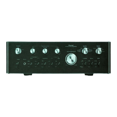
SWITCHES
AND
CONTROLS
Source
Selector
Indicator
Power
Indicator
The
Power
indicator
is
lit
when
the
Power
switch
is
turned
on.
It
remains
lit
while
the
amplifier
is
on.
Speakers
Switch
Three
pairs
of
speakers
can
be
connected
to
the
amplifier.
You
can
install
the
main
set
of
speak-
ers
(System
A)
in
your
listening
room
and
addi-
tional
speakers
(System
B
and
C)
in
the
same
room
or
remotely
in
other
rooms
of
your
home.
With
the
P-M
connector
removed,
the
amplifier
and
the
speakers
connected
to
the
System
C
out-
puts
can
be
used
asa
component
of
the
Electronic
Crossover
System.
OFF:
All
speakers
connected
to
the
amplifier
are
muted
for
private
listening
with
headphones
connected
to
the
Phones
jack.
SYSTEM
A:
Selects
the
speakers
connected
to
the
System
A
terminals.
SYSTEM
B:
Selects
the
speakers
connected
to
the
System
B
terminals.
SYSTEM
A+B:
Selects
the
A
and
B
speakers
simultaneously.
SYSTEM
C:
Selects
the
speakers
connected
to
the
System
C
terminals.
Power
Switch
Power
is
applied
to
the
amplifier
when
the
Power
switch
is
set
in
its
up
position.
This
switch
con-
trols
any
other
components
connected
to
the
upper
two
AC
outlets
on
the
rear
panel.
RE
PETTSMRE
TE
MSEC
TOE
RR
Sanstat.
Headphones
Jack
Plug
a
stereo
headset
into
this
jack
for
private
listening
or
monitoring.
This
jack
will
accept
any
standard
stereo
phone
plug,
but
a
dynamic
head-
set
is
recommended.
Balance
Check
Switch
——————-__—_
This
switch
is
used
to
check
whether
the
sound
levels
from
both
right
and
left
speakers
are
equal.
Turn
the
Mode
switch
to
any
MONO
position;
turn
all
Tone
Selector
switches
to
DEFEAT;
set
the
Balance
Check
switch
to
the
Jown
or
TEST
position;
and
adjust
the
Balance
mmtrol
so
that
the
sound
levels
from
both
speaters
are
:
minimized.
When
not
in
use,
make
wre
this
switch
is
in
its
up
position.
Note:
Headphones
cannot
be
controlled
by
this
switch.
Balance
unequal
sound
levels
fmxrn
both
speakers
as
described
above,
and
then
use
the
headphones.
Volume
Control
This
control
adjusts
the
over-all
sound
level
of
both
channels.
Turn
it
clockwise,
and
the
volume
is
increased;
and
vice
versa.
Source
Selector
Switch
This
switch
selects
from
among
the
various
pro-
yram
sources
connected
to
the
input
jacks
on
the
rear
panel
of
the
amplifier.
MIc:
Selects
a
50kQ
microphone
or
micro-
phones
connected
to
the
MIC
inputs.
PHONO
1:
Selects
a
record
player
having
a
50
kQ
cartridge
connected
to
the
PHONO
1
inputs.
PHONO
2:
Selects
a
record
player
having
a
30,
50
or
100
kQ
cartridge
connected
to
the
PHONO
2
inputs.
AUX:
Selects
other
components
connected
to
the
AUX
inputs.
TUNER:
To
select
a
tuner
connected
to
the
TUNER
inputs,
set
the
lever
to
its
down
or
TUNER
position.
When
not
in
use,
it
must
be
in
its
up
position.
Mode
Switch
STEREO
REVERSE:
Use
this
position
if
the
channels
of
a
stereo
program
are
reversed.
The
Mode
switch
connects
the
left
input
to
the
right
speaker
and
the
right
input
to
the
left
speaker.
STEREO
NORMAL:
Use
this
position
if
the
stereo
program
is
normal.
The
Mode
switch
con-
nects
the
left
input
to
the
left
speaker
end
the
right
input
to
the
right
speaker.
MONO
L+R:
The
Mode
switch
in
this
position
connects
the
left
and
right
inputs
to
bothspeak-
ers.
MONO
L:
The
Mode
switch
in
this
position
connects
the
left
input
to
both
speakers.
MONO
R:
The
Mode
switch
in
this
position
connects
the
right
input
to
speakers.
Balance
Control
This
control
adjusts
for
equal
sound
fron
both
left
and
right
channels
to
compensate
fo;
slight
imperfections
in
program
material,
variaions
in
speaker
output,
and
the
vagaries
of
room
a@cous-
tics.
Treble
Control
This
control
determines
the
amount
of
treble
tone
in
both
channels.
When
the
marker
is
centered
at
the
0
position,
the
response
curve
is
flat.
The
control
emphasizes
the
treble
tone
by
2
dB
per
step
as
it
is
turned
clockwise.
To
decrease
the
treble
loudness,
turn
it
counterclockwise.
Midrange
Control
This
contro]
determines
the
amount
of
midrange
in
both
channels.
When
the
marker
is
centered
at
the
0
position,
the
response
curve
is
flat.
The
contro]
emphasizes
the
midrange
by
1
dB
per
step
as
it
is
turned
clockwise.
To
decrease
the
midrange
loudness,
turn
it
counterclockwise.
Bass
Control
This
control
determines
the
amount
of
bass
tones
in
both
channels.
When
the
marker
is
centered
at
the
0
position,
the
response
curve
is
flat.
The
control
emphasizes
the
bass
tone
by
2
dB
per
step
as
it
is
turned
clockwise.
To
decrease
the
bass
loudness,
turn
it
counterclockwise.
Bass
Tone
Selector
This
switch
selects
the
frequency
at
which
the
Bass
control
begins
to
cut
or
boost.
DEFEAT:
Use
this
position
for
flat
response
at
low
frequencies.
200Hz:
The
Bas
cosntrol
begins
to
cut
or
boost
the
bass
tone
at
200
Hz.
400
Hz:
The
Bass
control
begins
to
cut
or
boost
the
bass
tone
at
400
Hz.
Midrange
Tone
Selector
This
switch
selects
the
frequency
at
which
the
Midrange
control
begins
to
cut
or
boost.
DEFEAT:
Use
this
position
for
flat
response
at
mid-frequencies.
1kHz:
The
Midrange
control
begins
to
cut
or
boost
the
midrange
at
1000
Hz.
2kHz:
The
Midrange
control
begins
to
cut
or
boost
the
midrange
at
2000
Hz.
Treble
Tone
Selector
This
switch
selects
the
frequency
at
which
the
Treble
control
begins
to
cut
or
boost.
DEFEAT:
Use
this
position
for
flat
response
at
high
frequencies.
6kHz:
The
Treble
control
begins
to
cut
or
boost
the
highs
at
6000
Hz.
3kHz:
The
Treble
control
begins
to
cut
ox
boost
the
highs
at
3000
Hz.
Low
Filter
Turntable
rumble
and
other
low-frequency
noises
are
reduced
by
setting
the
Low
Filter
sv
itch
to
the
ON
position.
High
Filter
Surface
noise
from
old
or
worn
records,
tipe
hiss
and
other
high-frequency
noises
are
reduced
by
setting
the
High
Filter
switch
to
the
ON
position.
Tape
Monitor
Switch
Two
stereo
tape
decks
can
be
connected
to
the
amplifier.
When
using
3-head
tape
decks,
this
switch
allows
recording
directly
from
any
program
set
up
on
the
amplifier,
and
at
the
same
time
al-
lows
listening
to
the
actual
recording
as
picked
up
by
the
playback
head.
DECK
1:
Selects
the
tape
deck
connected
to
the
TAPE
1
or
TAPE
RECORDER
jacks.
DECK
2:
Selects
the
tape
deck
connected
to
the
TAPE
2
jacks.
When
not
in
use,
make
sure
the
switch
is
in
the
SOURCE
position.
Muting
Switch
The
Muting
switch
attenuates
music
and
voice
by
20dB
over
the
whole
frequency
range
without
use
of
the
Volume
control.
This
switch
is
used
to
suppress
the
background
noise
heard
when
changing
a
record,
and
to
reduce
the
over-all
sound
level
temporarily
while
playing
a
record.
Tape-to-Tape
Reprint
When
connecting
two
tape
decks
to
the
amplifier,
this
switch
allows
tape-to-tape
recording.
DECK
1-2:
Use
this
position
for
recording
from
tape
deck
1
to
tape
deck
2.
SOURCE
RECORD:
With
the
switch
in
this
position,
any
program
source
selected
by
the
Source
Selector
switch
can
be
recorded
by
either
deck
1
or
2,
or
by
both
decks
simultaneously.
DECK
2-+1:
Use
this
position
for
recording
from
tape
deck
2
to
tape
deck
1.
Note:
During
the
tape-to-tape
reprinting
process,
monitoring
is
possible
on
either
recording
or
play-
back
side
by
setting
the
Tape
Monitor
switch
to
the
DECK
1
or
DECK
2
position.
When
the
Tape
Monitor
switch
is
returned
to
the
SOURCE
position,
it
is
possible
to
play
a
record
as
usual
while
reprinting.
SPEAKER
CONNECTIONS
___
RECORD
PLAYING
Connecting
Loudspeakers
Three
pairs
of
4-
to
16-ohm
speakers
can
be
con-
nected
to
the
amplifier.
One
set
of
speakers
con-
nected
to
the
SYSTEM
A
terminals
may
be
installed
in
your
listening
room
and
two
other
sets
of
speakers
connected
to
the
SYSTEM
B
and
C
outputs
may
be
installed
in
other
rooms
of
your
home.
The
Speakers
switch
selects
from
among
the
A,
B
and
C
speakers.
When
it
is
set
to
the
SYSTEM
A+B
position,
you
will
hear
sound
from
both
speaker
systems.
Only
the
C
speakers
can
be
used
as
a
component
of
the
Electronic
Crossover
System.
A
detailed
description
will
be
found
in
the
section
en-
titled
Electronic
Crossover
System.
To
connect
the
main
set
of
speakers
to
the
ampli-
fier:
1.
Connect
the
positive
terminal
of
the
speaker
on
your
right
(as
viewed
from
the
listening
area)
to
the
right
channel
SYSTEM
A
(+)
terminal
on
the
rear
of
the
amplifier.
2.
Connect
the
lead
from
the
negative
speaker
terminal
(marked
—)
to
the
right
channel
SYS-
TEM
A
(—)
terminal
on
the
rear
of
the
amplifier.
3.
The
left
speaker
connections
are
made
at
the
left
channel
SYSTEM
A
terminals
on
the
rear
of
the
amplifier
in
the
manner
described
above.
4,
Set
the
SPEAKERS
selector
to
SYSTEM
A.
In
connecting
speakers
to
the
amplifier,
no
more
than
44-inch
of
insulation
should
be
removed
from
the
end
of
a
speaker
cable,
since
any
greater
length
of
exposed
wire
is
likely
to
cause
shorts
at
the
ter-
minals.
Al!
wire
strands
should
be
tightly
twisted.
To
connect,
depress
the
terminal
button
with
one
hand,
push
the
stripped
end
of
lead
wire
in
the
hole
with
the
other
hand,
and
release
the
button.
1f
you
wish
to
connect
one
or
two
more
sets
of
speakers
in
the
same
room
or
remotely,
you
can
connect
such
speakers
to
the
SYSTEM
B
and
C
terminals
of
each
channel
as
indicated
above.
To
listen
to
sound
from
the
B
or
C
speakers,
be
sure
to
turn
the
Speakers
switch
to
the
SYSTEM
B
or
C
position
respectively.
RECORD
PLAYERS
Connecting
Record
Players
The
AU-999
has
two
sets
of
PHONO
inputs
to
accommodate
a
pair
of
players.
The
PHONO
1
has
the
input
impedance
of
50
kQ.
The
PHONO
2
can
be
switched
between
30,
50
and
100k
by
means
of
the
PICKUP
LOAD
switch
on
the
rear
panel.
To
connect
a
record
player
to
the
amplifier,
proceed
as
follows:
1.
Connect
the
left
channel
output
of
the
record
player
to
the
LEFT
PHONO
1
(or
PHONO
2)
input
jack
on
the
rear
of
the
amplifier.
2.
Connect
the
right
channel
output
of
the
record
player
to
the
RIGHT
PHONO
1
(or
PHONO
2)
input
jack.
3.
If
a
monophonic
player
or
turntable
is
used,
it
may
be
connected
to
either
LEFT
or
RIGHT
PHONO
input
jack.
Listening
to
a
Stereo
or
Mono
Record
1.
Set
the
SOURCE
SELECTOR
switch
to
PHO-
NO
1
or
PHONO
2
depending
on
which
input
is
being
used.
Check
the
TUNER
SELECTOR
switch
to
see
if
it
is
in
its
up
position.
2.
Set
the
MODE
switch
to
STEREO.
Ifa
mono-
phonic
record
player
is
used,
set
the
MODE
switch
to
MONO.
3.
Make
appropriate
settings
of
controls
on
the
record
player.
4,
Place
the
needle
on
the
record.
5.
Adjust
the
BALANCE
control
for
equal
sound
from
both
right
and
left
speakers.
6.
Use
all
other
controls
and
switches
accorcling
to
your
personal
taste
and
room
acoustics.
Note:
When
monophonic
records
are
played
on
a
stereo
player,
follow
the
same
procedures
as
for
stereophonic
records
for
better
results.
Insert
the
power-cord
plug
of
the
player
int»
one
of
the
two
A.C.
outlets
marked
SWITCHED
on
the
rear
of
the
amplifier.
The
power
supply
wall
then
be
controlled
by
the
front
POWER
switch.
===
LEFT
CHANNEL
RIGHT
CHANNEL
VOLTAGE
SELECTOR...
wi
PM
CONNECTOR
MAY
VOLTAGE
SELECTOR
PLUG
CONNECTING
TO
SPEAKER
TERMINALS
TO
PICKUP
RECORD
PLAYER
LOAD
SWITCH
RECORD
PLAYER
Dae
sian.
POWER
FUSE
|
GROUNDING
|
LEVEL
ADJUST
GROUNDING
——
SYSTEM
A
ecenetan
es
elazetenon!
HRN
|:
SRNR
RO
RRO
CR
Es
RIGHT
SPEAKER
LEFT
SPEAKER
LEFT
SPEAKER
RIGHT
SPEAKER
LEFT
SPEAKER
RIGHT
SPEAKER
ag)
RADIO
RECEPTION
___
MICROPHONES
TUNERS
Connecting
Tuners
For
a
stereo
tuner,
connect
its
left
channel
output
to
the
left
channel
TUNER
input
jack,
and
its
right
channel
output
to
the
right
channel
TUNER
input
jack.
For
a
monophonic
tuner,
connect
its
output
to
either
left
or
right
jack.
For
use
with
an
FM-
MPX
adaptor,
connect
the
tuner
output
to
the
adaptor
input;
then
connect
the
left
channel
output
of
the
adaptor
to
the
left
channel
TUNER
jack,
and
the
right
channel
output
of
the
adaptor
to
the
right
channel
TUNER
jack.
Listening
to
a
Stereo
FM
Program
1.
Set
the
TUNER
SELECTOR
switch
to
its
down
or
TUNER
position.
2.
Set
the
MODE
switch
to
STEREO.
3.
Use
tuning
controls
to
reach
the
desired
station.
Make
appropriate
settings
of
controls
on
the
tuner.
4,
Adjust
the
amplifier’s
front
panel
controls
and
switches
according
to
your
personal
taste
and
room
acoustics.
Listening
to
a
Mono
Program
1.
Set
the
TUNER
SELECTOR
switch
to
its
down
or
TUNER
position.
2.
Set
the
MODE
switch
to
MONO.
3.
Use
tuning
controls
to
reach
the
desired
station.
Make
appropriate
settings
of
controls
on
the
tuner.
4,
Adjust
the
amplifier’s
front
panel
controls
and
switches
according
to
your
personal
taste
and
room
acoustics.
For
Use
with
an
FM-MPX
Adaptor
1.
Set
the
TUNER
SELECTOR
switch
to
its
down
or
TUNER
position.
2.
Set
the
MODE
switch
to
STEREO.
3.
Use
tuning
controls
to
reach
the
desired
station.
4.
Make
appropriate
settings
of
controls
on
the
FM-MPX
adaptor.
5.
Adjust
the
amplifier’s
front
panel
controls
and
switches
according
to
your
personal
taste
and
room
acoustics.
MICROPHONES
One
or
two
microphones
can
be
connected
to
the
MIC
inputs
on
the
rear
of
the
amplifier.
Use
high-
impedance
50-kQ
dynamic
or
velocity
microphones
for
optimum
performance.
Connections
If
two
microphones
are
used,
connect
one
to
the
RIGHT
MIC
input
and
the
other
to
the
LEFT.
If
only
one
microphone
is
used,
connect
it
to
either
RIGHT
or
LEFT
MIC
input.
‘
Ee
Biaiictiey
\“Shieided®
wire:
Operation
1.
Turn
the
SOURCE
SELECTOR
switch
to
MIC.
Check
the
TUNER
SELECTOR
switch
to
see
if
it
is
in
its
up
position.
2.
If
two
microphones
are
used,
set
the
MODE
switch
to
MONO
L+R
for
mixing
the
two
input
signals
or
to
STEREO
for
separate
use
of
the
two
microphones.
If
only
one
microphone
is
used,
set
the
MODE
switch
to
MONO
L
or
MONO
R
de-
pending
on
which
input
is
being
used.
3.
Use
all
other
controls
and
switches
according
to
taste
and
listening
conditions.
CAUTION:
When
you
connect
one
set
of
speakers
to
the
SYSTEM
A
terminals
and
another
set
of
speakers
to
the
SYSTEM
B
in
order
to
use
them
simultaneously
with
the
Speakers
switch
set
in
its
SYSTEM
A+B
position,
each
speaker
must
have
impedance
of
8ohms
or
more.
If
a
4ohm
im-
pedance
speaker
is
used,
the
amplifier
may
be
damaged.
FM
MPX
ADAPTOR}
TO
TUNER
SEE
‘SPEAKER
CONNECTION”
WALL
0UITLET
oe
LEFT
CHANNEL
RIGHT
CHANNEL
MICROPHONE
(50
k{))
==
4o°
OPERATIONS
——
TAPE
PLAYBACK
——
TAPE
RECORDING
TAPE
DECKS
Connecting
Tape
Decks
Tape
decks
can
be
connected
to
record
from,
and
playback
through,
the
AU-999.
Tape
monitoring
is
possible
with
a
tape
machine
having
a
built-in
pre-amplifier
as
well
as
separate
recording
and
playback
heads.
Tape
Deck
with
DIN
Connector
If
your
tape
deck
has
a
DIN
(German
Industrial
Standard)
5-pin
plug,
plug
it
into
the
TAPE
RE-
CORDER
socket
on
the
rear
panel
of
the
amplifier.
Caution:
The
tape
deck
having
a
DIN
connector
must
not
be
used
together
with
another
tape
deck
connected
to
the
TAPE
1
jacks.
To
use
both
decks
simultaneously,
the
latter
tape
deck
should
be
con-
nected
to
the
TAPE
2
jacks.
Pin-Jack
Tape
Deck
To
record
on
tapes
from
the
amplifier:
1.
Connect
the
left
channel
input
of
the
tape
deck
to
the
left
channel
TAPE
1
(or
2)
REC
jack
on
the
rear
of
the
amplifier.
2.
Connect
the
right
channel
input
of
the
tape
deck
to
the
right
channel
TAPE
1
(or
2)
REC
jack.
3.
If
a
monophonic
tape
recorder
is
used,
it
may
be
connected
to
either
left
or
right
TAPE
REC
jack.
To
playback
through
the
amplifier:
1.
Connect
the
left
channel
output
of
the
tape
deck
to
the
left
channel
TAPE
1
(or
2)
PLAY
jack
on
the
rear
of
the
amplifier.
2.
Connect
the
right
channel
output
of
the
tape
deck
to
the
right
channel
TAPE
1
(or
2)
PLAY
jack,
3.
Ifa
monophonic
tape
recorder
is
used,
it
may
be
connected
to
either
left
or
right
TAPE PLAY
jack.
Recording
on
Tapes
1.
Set
the
SOURCE
SELECTOR
switch
to
the
program
to
be
recorded.
2.
Set
the
MODE
switch
to
STEREO.
Ifa
mono-
phonic
tape
recorder
is
used,
set
the
switch
to
MONO.
3.
Make
appropriate
settings
of
controls
on
the
tape
deck.
To
record
on
a
pair
of
tapes
simultaneously
by
using
two
tape
decks
connected
to
the
TAPE
1
and
2
jacks:
1.
Set
the
SOURCE
SELECTOR
switch
to
the
program
to
be
recorded.
2.
Set
the
TAPE-TO-TAPE
REPRINT
switch
to
SOURCE
RECORD.
3.
Set
the
tape
decks
in
the
recording
mode.
4,
Use
other
controls
and
switches
appropriately.
Listening
to
Tapes
1.
Turn
the
TAPE
MONITOR
switch
to
PLAY
BACK DECK
1
or
2.
2.
Set
the
MODE
switch
to
STEREO.
Ifa
mono-
phonic
tape
recorder
is
used,
set
the
switch
to
MONO.
3.
Make
appropriate
settings
of
controls
on
the
tape
deck.
4.
Use
the
amplifier’s
front
panel
controls
and
switches
according
to
your
personal
taste
and
listen-
ing
conditions.
Tape
Monitoring
Monitoring
is
possible
only
with
a
tape
deck
which
has
its
own
playback
preamplifier
as
well
as
separate
recording
and
playback
heads.
Set
the
TAPE
MONITOR
switch
to
PLAYBACK
and
use
all
other
controls
and
switches
according
to
your
personal
taste
and
listening
conditions.
‘Tape-to-Tape
Reprinting
To
record
from
the
tape
deck
connected
to
the
TAPE
1
jacks
to
the
tape
deck
connected
to
the
TAPE
2
jacks:
1.
Turn
the
TAPE-TO-TAPE
REPRINT
switch
to
DECK
1
->
2.
2.
Set
tape
deck
2
in
the
recording
mode.
3.
Set
tape
deck
1
in
the
playback
mode.
4,
Use
other
controls
and
switches
approprately.
To
record
from
tape
deck
2
to
tape
deck
1:
1.
Turn
the
TAPE-TO-TAPE
REPRINT
switch
to
DECK
2
—
1.
2.
Set
tape
deck
1
in
the
recording
mode.
3.
Set
tape
deck
2
in
the
playback
mode.
4,
Use
other
controls
and
switches
appropriately.
Notes:
l.
Tape
recorded
sound
cannot
be
controlled
by
the
controls
and
switches
on
the
front
panel
of
the
amplifier.
They
control
sound
from
the
speakers
only.
®.
For
better
results,
record
directly
through
the
RECORD-
ING
}
TAPE
DECK
iS
PLAYBACK
erm
ene
ieenemeemeremenennennnnninnnitnimememnnnell
AU-999,
rather
than
through
microphones
placed
in
front
of
the
speakers.
3.
Before
connecting
and
operating
the
tape
decks,
be
sure
to
look
up
the
manufacturer’s
operating
instructions.
4.
The
TAPE
MONITOR
switch
should
be
in
the
SOURCE
position
except
when
the
tapes
are
being
monitored
or
played
back
by
the
tape
deck.
When
the
switch
is
in
the
PLAY
BACK
position,
signals
from
any
other
source
will
not
be
heard
from
the
speakers.
RECORDING
TO
TAPED
ECK
A
(0
ae
_
moa.
|
‘ig
@@
1
@@
,
PLAYBACK
TAPE
DECK
‘SEE
“SPEAKER
CONNECTION”
LEFT
CHANNEL
RIGHT
CHANNEL
—
12
—
Electronic
Crossover
System
The
electronic
crossover
system
is
said
to
be
the
best
hi-fi
sound
reproduction
method
available,
featuring
the
following
advantages:
1.
Since
the
tweeters,
midranges
and
woofers
have
their
own
amplifier,
any
speakers
of
different
im-
pedance
and
efficiency
can
be
used
for
stereo
ar-
rangement.
2.
This
system
has
better
filter
characteristics
than
the
conventional
LC
crossover
network.
You
can
determine
the
optimum
crossover
points
for
the
speakers
used.
3.
Since
there
is
no
component
between
the
ampli-
fier
and
speaker,
the
damping
factor
of
the
amplifier
is
not
affected
and
it
is
directly
coupled
to
the
speaker.
4.
This
system
allows
use
of
the
power
amplifiers
effectively
and
efficiently.
For
instance,
a
big-power
amplifier
can
be
used
for
woofers,
and
ones
with
good
characteristics
for
midranges
and
tweeters.
You
can
select
the
amplifiers
suitable
for
each
of
the
woofers,
midranges
and
tweeters.
The
AU-999’s
preamp
and
main
amplifier
sections
can
be
used
separately
by
simply
removing
a
pair
of
connectors
from
the
PRE
OUTPUT
and
MAIN
INPUT
jacks
on
the
rear
panel.
This
feature
en-
ables
you
to
use
the
AU-999
as
a
component
of
an
Electronic
Crossover
System
in
the
following
man-
ner:
1.
Set
the
SPEAKERS
switch
to
SYSTEM
C.
2.
Remove
the
two
connectors
from
the
PRE
OUT-
PUT
and
MAIN
INPUT
jacks.
3.
Connect
an
electronic
crossover
unit
(Sansui
CD-5)
to
the
PRE
OUTPUT
jacks.
4.
Connect
the
low-frequency
output
of
the
electro-
nic
crossover
unit
to
the
MAIN
INPUT
jacks
on
the
AU-999.
5.
Connect
the
right
and
left
woofers
to
the
SYS-
TEM
C
terminals
on
the
AU-999.
6.
Connect
the
mid-frequency
output
of
the
elec-
tronic
crossover
unit
to
the
inputs
of
the
second
separate
power
amplifier
(Sansui
BA-90),
and
the
right
and
left
midrange
speakers
to
the
said
power
RONIC
CROSSOVER
SYSTEM
amplifier.
7.
Connect
the
high-frequency
output
of
the
elec-
tronic
crossover
unit
to
the
inputs
of
the
third
sepa-
rate
power
amplifier
(Sansui
BA-90),
and
the
right
and
left
tweeters
to
the
said
power
amplifier.
Notes:
1.
You
can
connect
speakers
to
the
SYSTEM
A
and
B
terminals
in
addition
to
the
SYSTEM
C
and
directly
compare
the
sound
of
the
Electronic
Crossover
System
with
that
of
the
ordinary
stereo
arrangement
by
turning
the
SPEAKERS
switch
between
the
SYSTEM
A,
B
and
C
positions.
2.
The
connection
of
an
additional
pre-amplifier
to
the
MAIN
INPUT
jacks
cuts
off
all
front
panel
switches
and
controls
except
the
BALANCE
CHECK
and
SPEAKERS
switches.
Thus,
to
adjust
the
tone
and
volume,
operate
the
controls
of
the
additional
pre-amplifier
connected
to
the
AU-999.
When
an
additional
power
amplifier
is
connected
to
the
PRE
OUTPUT
jacks,
the
tone
and
volume
can
be
adjusted
by
the
controls
of
the
AU-999.
13:
—
BASIC
AMP.
FO
HIGH
RANGE
0
a
ae
BASIC
AMP.
FOR
MIDRANGE
,
ELECTRONIC
|
CROSSOVER
UNIT
RECORD
PLAYER
PRE-AMP.
OUTPUT
BASIC
AMP.
INPUT
FOR
LOW
RANGE
2,
ARR
‘
SSNS
RRR)
RRR
ean
LEFT
CHANNEL
RIGHT
CHANNEL
WOOFER
_
LEFT
SPEAKER
©
TWEETER
RIGHT
SPEAKER
MAINTENANCE
PM
Connectors
Warning:
Be
sure
to
turn
the
POWER
switch
OFF
before
removing
the
PM
connectors.
The
PM
connectors
hook
up
the
PRE
OUTPUT
and
MAIN
INPUT
terminals
on
the
rear
panel
of
the
amplifier.
When
the
PM
connectors
are
remov-
ed
with
the
SPEAKERS
switch
set
in
the
SYS-
TEM
C
position,
the
pre-and
main
amplifier
sections
can
be
used
individually
and
separately.
They
should
not
be
removed
except
when
connecting
additional
pre-
and/or
main
amplifiers.
Refer
to
the
section
en-
titled
Electronic
Crossover
System.
Level
Adjustments
AUX:
This
level
control
determines
the
strength
of
signals
fed
into
the
AUX
inputs.
PHONO
1
and
2:
Two
level
controls
are
provided
to
adjust
the
loudness
of
each
phonograph
input.
Adjust
these
controls
so
that
there
will
not
be
any
difference
in
the
loudness
level
between
the
PHONO
1
and
2
inputs.
To
increase
the
loudness
level,
turn
the
controls
clockwise
with
a
screwdriver;
to
decrease,
turn
them
counterclockwise.
Connecting
Wire
Be
sure
to
use
adequately
thick
shieldwire
when
connecting
tape
decks,
record
players
or
other
components
to
the
AU-999.
The
use
of
an
ordi-
nary
twin
leadwire
may
cause
hum
or
noise.
Don’t
use
shieldwire
longer
than
7
feet
(2
meters).
The
use
of
a
longer
wire
leads
to
greater
attenuation
at
high
frequencies.
CONNECTING
SHIELDED
CABLE:
TO
A
PIN.
PLUG
Connections
Always
check
to
see
that
leads
are
connected
firmly
and
properly
to
their
corresponding
output
or
input
terminals.
If
the
connections
are
loose
or
in
touch
with
other
parts,
the
AU-999
will
not
perform
normally,
and
may
produce
undesirable
noise.
If
used
in
such
a
way
for
a
long
time,
it
will
eventually
break
down.
Always
read
the
manufacturer’s
in-
structions
for
tape
decks,
record
players,
etc.
before
connecting.
Where
to
Place
Since
transistors
are
extremely
susceptible
to
heat,
the
AU-999
has
been
designed
to
diffuse
heat
through
the top
and
rear
of
its
case.
Therefore,
special
consideration
should
be
given
to
where
it
will
be
used
before
installing
the
system.
It
should
not
be
operated
in
a
place
where
it
is
exposed
directly
to
the
sun,
near
radiators
or
other
heat-
generating
sources,
and
it
should
never
be
mounted
in
an
air-tight
cabinet.
Finally,
nothing
shoald
be
placed
on
top
of
it.
—
15
—
Hum
and
Howling
If,
when
using
a
tape
deck
or
record
player,
unpleasant
humming
or
howling
is
heard,
it
1s
usually
a
result
of
the
following.
The
record
player
is
placed
on
or
near
the
speaker
box
causing
sound
waves
to
be
transmitted
from
the
speaker
to
the
player
(howling).
To
prevent
this,
place
the
record
player
away
from
the
speaker
box
or
put
a
thick
cushion
between
the
two
com-
ponents.
A
low
buzzing
sound
will
also
be
produced
if
ade-
quately
thick
shieldwire
is
not
used
for
connections,
or
if
connections
have
not
been
properly
made.
Be
sure
that
the
shieldwire
is
properly
soldered
to
the
pin-plugs
as
illustrated
in
“Connecting
Wire”,
and
that
the
motor
and
pickup
arm
or
the
record
player
are
properly
grounded.
Speaker
Impedance
Combined
impedance
of
speakers
in
each
channel
should
not
be
less
than
4
ohms.
Too
low
impedance
may
blow
quick-acting
fuses
or
may
cause
damage
to
the
amplifier
after
use
over
a
long
period.
Phasing
of
Speakers
Stand
about
10
feet
in
front
of
and
midway
between
the
speakers
and
listen
to
any
monophonic
repro-
duction.
If
the
speakers
are
correctly
phased,
the
sound
will
seem
to
come
from
between
the
speakers.
If
the
sound
is
not
directly
in
front
of
you,
the
speakers
are
incorrectly
phased.
To
correct
this
switch
the
amplifier
off
and
reverse
the
leads
to
one
speaker.
Care
should
be
taken
not
te
connect
a
single
speak-
er
system
between
the
SYSTEM
A
and
B
termi-
nals,
a
minal
Grounding
Connect
one
end
of
vinyl
or
enameled
wire
to
the
terminal
screw
marked
GND
on
the
rear
of
the
amplifier,
attach
a
copper
plate
to
the
other
end
and
bury
it
underground.
Whenever
an
outdoor
AM
antenna
is
used,
grounding
becomes
necessary.
In
all
cases,
grounding
is
desirable
since
it
allows
a
better
SN
ratio
to
be
obtained.
To
ground
an
entire
audio
system,
connect
the
grounding
wire
of
each
component
used
to
this
terminal.
a
~
seeyeem
E
i
COPPER:
PLATE
a
_
[BURIED
UNDERGROUND:
as
{G5
Quick-Acting
Fuses
The
AU-999
is
double
protected
by
the
quick-acting
fuses
at
every
power
transistor
stage
and
in
the
power
circuit.
If
sound
from
the
speakers
is
distorted
or
not
heard
at
all,
immediately
remove
the
power
plug
from
its
outlet;
check
for
the
blown
SPEAK-
ER
FUSES
on
the
rear
panel;
and,
if
necessary,
replace
them
with
the
new
5-ampere
fuses
(sup-
plied).
If
OK,
remove
the
bonnet
from
the
AU-
999;
check
the
inside
fuses;
and,
if
necessary,
replace
them
with
the
new
5-ampere
fuses
(supplied).
Be-
fore
replacing,
check
for
the
source
of
trouble
that
caused
the
fuses
to
blow.
If
the
new
fuses
blow
as
soon
as
the
POWER
switch
is
turned
on,
check
for
the
defective
power
circuit.
If
the
trouble
source
cannot
be
located,
contact
the
nearest
Sansui
deal-
er
or
Service
Center.
A.C.
Outlets
The
AU-999
is
provided
with
five
A.C.
outlets
on
its
rear
panel.
The
upper
two
outlets
marked
ICE
/
ACCESSORIES
SWITCHED
are
switched
on
and
off
by
the
POW-
ER
switch
on
the
front
panel.
Caution:
The
upper
two
outlets
have
a
maxi-
mum
capacity
of
150
VA
total
and
the
three
other
outlets
300
VA
total.
Never
use
them
beyond
their
rated
capacities.
Power
Fuse
CAUTION:
For
the
power
supply
voltage
of
100
to
127
volts,
use
a
4-ampere
fuse;
for
220
to
250
volts,
use
a
3-ampere
fuse.
If
the
unit
remains
completely
dead
when
the
power
is
switched
on
(POWER
indicator
fails
to
light),
the
power
fuse
is
probably
blown.
In
this
case,
remove
the
power
plug
from
its
AC
outlet
and
replace
the
fuse
after
finding
and
eliminating
the
trouble
that
caused
the
fuse
to
blow.
(Consult
the
Troubleshoot-
ing
Section
in
your
Service
Manual)
Use
only
a
glass-tubed
4(or
3)-ampere
fuse
Never
attempt
to
use
a
piece
of
wire
or
a
fuse
of
a
tifferent
capacity
as
a
substitute.
Voltage
Adjustment
To
reach
the
voltage
selector,
remove
he
two
screws
from
the
nameplate
on
the
rear
pmel
and
then
remove
the
nameplate.
The
voltage
selector
makes
it
possible
to
operate
the
AU-999
at
the
correct
voltage
in
any
area.
The
voltage
bs
been
pre-adjusted
at
the
factory,
but
can
be
esaly
re-
adjusted
as
follows:
pas
lp
eee
srpeprnaemtpnen
siemens
sree’
STENT
get
a
ET
NASR
PPE
SCS
RET
SEI
POETS
EE
I
TITTIES
EE
LT
TLE
LEIS
ETE
ITE
INDE
TET
TTT
TIO
EET
STEP
I
Set
arrow
of
main
voltage
selector
plug
to
required
voltage:
100,
110, 117,
127,
220,
230,
240
or
250
volts.
STEP
IL
If
numerals
of
voltage
are
printed
in
red,
set
arrow
of
adjacent
sub
V.S.
plug
to
position
marked
red.
If
there
are
printed
in
white,
set
arrow
to
position
marked
white.
Note:
The
Voltage
Adjustor
can
be
also
used
to
eliminate
trouble
caused
by
considerable
voltage
fluctuation.
In
this
case,
it
should
be
set
to
the
peak
voltage.
Accessories
List
1.
OPERATING
INSTRUCTIONS
AND
SERVICE
MANUAL
......0..
ee
1
2:
OPERATING
SHEET
2.440
othe
Aaa.
a
1
2.
PINSPLUGS
eid
idsteieds
up
cae
sieesoate
es
4
4.
MIC-PLUG
woe
ci
ete
asians
2
5.
QUICK
ACTING
FUSES
(SPEAKER
PUSES)OAL
ct
ccasas
uncyasseveusaransass
See
4
en
POLISHING
CLOTH.
osteo
ae
oe
7.
BUTTERFLY
BOLT
Sissi
escci
as
ae
hth
Bi
WASHERS:
ors
cssree
ciate
ieee
Ae,
Se
PO
MP
Fe
NM
—
18
—
POWER
AMPLIFIER
SECTION:
POWER
OUTPUT:
MUSIC
POWER
(IHF):
180W
at
4
ohms
load
140W
at
8
ohms
load
CONTINUOUS
POWER:
70/70W
at
4
ohms
load
50/50W
at
8
ohms
load
TOTAL
HARMONIC
DISTORTION:
less
than
0.4%
at
rated
output
INTERMODULATION
DISTORTION
(60Hz:
7,000Hz=4:1
SMPTE
method)
less
than
0.4%
at
rated
output
POWER
BANDWIDTH
(IHF)
10
to
30,000Hz
at
8
ohms
load
FREQUENCY
RESPONSE
(at
normal
listning
level):
5
to
100,000Hz
+
1dB
CHANNEL
SEPARATION
(at
1,000Hz,
rated
out-
put):
better
than
50dB
HUM
AND
NOISE
(IHF)
better
than
100dB
INPUT
SENSITIVITY:
1V
for
rated
output
INPUT
IMPEDANCE:
50k
ohms
LOAD
IMPEDANCE:
4
to
16
ohms
DAMPING
FACTOR:
45
at
8
ohms
load
PRE-AMPLIFIER
SECTION
OUTPUT
VOLTAGE:
MAXIMUM
OUTPUT
VOLTAGE:
5V
RATED
OUTPUT
VOLTAGE:
1Vv
TOTAL
HARMONIC
DISTORTION:
less
than
0.1%
at
rated
output
voltage
FREQUENCY
RESPONSE:
20
to
70,000Hz
+
0.5dB—1.5dB
HUM
AND
NOISE
(IHF):
PHONO-1
and
2:
better
than
80dB
MIC:
better
than
80dB
TUNER
and
AUX:
better
than
85dB
INPUT
SENSITIVITY
(at
1,000Hz,
rated
output
voltage)
PHONO-1
2mV
(50k
ohms)
PHONO-2
2mV
(30k,
50k,
100k
ohms)
MIC:
3mV
(50k
ohms)
TUNER:
200mV
(50k
ohms)
AUX:
200mV
(50k
ohms)
TAPE
MON
(pin):
200mV
(50k
ohms)
TAPE
RECORDER
(DIN):
200mV
(50k
ohms)
RECORDING
OUTPUT:
TAPE
REC
(pin):
200mVv
TAPE
RECORDER
(DIN):
30mv
EQUALIZER:
PHONO,
MIC:
NF
type
—
19
CONTROLS:
BASS:
+12dB—8dB8
at
20Hz
MIDRANGE:
+
5dB—5dB
at
1,000Hz
or
2,000Hz
TREBLE:
+12dB—8dB
at
20,000Hz
TONE
SELECTOR:
BASS:
DEFEAT,
200Hz,
400Hz
MIDRANGE:
DEFEAT,
1,000Hz,
2,000Hz
TREBLE:
DEFEAT,
6,000Hz,
3,000Hz
SWITCHES:
LOW
FILTER:
—20dB
at
20Hz
(12dB/oct,
NF
type)
HIGH
FILTER:
—18dB
at
20,000Hz
(12dB/oct,
NF
type)
MUTING:
—20dB
MODE:
STEREO-REV,
STEREO-NORM,
MONO-L+R,
MONO-L,
MONO-R
SOURCE
SELECTOR:
MIC,
PHONO-1,
PHONO-2,
AUX
TUNER
SELECTOR:
OFF,
ON
TAPE
MONITOR:
PLAYBACK
DECK-1,
SOURCE,
PLAYBACK
DECK-2
TAPE
TO
TAPE
REPRINT:
DECK-1
to
2
SOURCE
RECORD,
DECK-2
to
1
SPEAKER
SELECTOR:
OFF,
SYSTEM-A,
SYSTEM-B,
SYSTEM-A+B,
SYSTEM-C
(PRE-
and
MAIN
SEPARATED)
BALANCE
CHECK:
NORMAL,
TEST
THE
OTHER
ACCESSORIES:
5-pin
DIN
socket
for
Tape
Recorder,
Head
Phone
Jack,
Input
Level
Adjuster
for
PHONO-1,
PHONO-2
and
AUX,
One-toutch
clip
type
Speaker
Terminals
Source
Selector
Indicator
TRANSISTORS
AND
DIODES:
Transistors;
41
Diodes;
16
Triac;
2
POWER
REQUIREMENTS:
POWER
VOLTAGE:
100,
110,
117,
127,
220,
230,
240,
250V
50/60Hz
POWER
CONSUMPTION:
370W
(max.
signal)
DIMENSIONS:
18144"W
x
614"Hx124%"D
WEIGHT:
38.5
Ibs.
CHARACTERISTICS
MUSIC
POWER
(%)
DISTORTIO
LOW/HIGH
FILTER
DISTORTION
(%}
PUT
—AUX
OUTPUT-8Q
LOAD
FREQUENCY-60Hz+7KH
%)
oO
=
oO oO
ro
|
IM
DISTORTION
a
0
2)
}
||
-4|
44
hese
mae
=—-6
1
$8
tw-10)
a
+
tt
B-12
{it
nt
S-14
INPUT—AUX
Wi
16
4+
QUTPUT-82.
LOAD
HH
«18
ToT
20!
wap
+4
Soe
it
“2650
100
500
IK
5K
10K.
50K
FREQUENCY
(Hz)
TRIPLETONE
CONTROL
iat
HF
ineut—aux
|
16
OUTPUT-82LOAD
ot
Math
TONE
SELECTOR-400Hz,
2KHz,
3KH2z
=H]
Bio
[|
|
Be
5
4
0
2h
wc
O
~2
-4
ar
eae
-8l
Secon
ally
50
100.
500
IK
BK
OK
SOKIOOK
|
FREQUENCY
(Hz)
TRIPLETONE
CONTROL
18
6
INPUT—AUX
14
OUTPUT—82.
LOAD
ia
TONE,
SELECTOR-200Hz,
IKHz,6KHz
a8
a
i
36
bl
4
56
~2
a-4
6
-8
-10
ia
|
r
1250
100.
500
IK
BK
OK
SOK
I00K
FREQUENCY
(Hz)
{
|
50
(oe)
500
IK
SK
FREQUENCY
(Hz
1OK
HHH
|
Ll
mH
Ol
05
]
io)
10
50
POWER
OUTPUT
(W)
POWER
BANDWIDTH
[
mnt
BO
~-|
Q-2
!
2-3
INPUT—AUX
i
o,
OUTPUT-82
LOAD
Wy
OdB-50W,/0.5%
Ft
ct
1
I
L
|
SOK
—
20
——

Other manuals for AU-999

1

Other Sansui Amplifier manuals

Sansui AU-777A Troubleshooting guide

Sansui

Sansui AU-777A Troubleshooting guide

Sansui AU-9500 Troubleshooting guide

Sansui

Sansui AU-9500 Troubleshooting guide

Sansui RA-700 User manual

Sansui

Sansui RA-700 User manual

Sansui AU-D11 II User manual

Sansui

Sansui AU-D11 II User manual

Sansui AU-5900 User manual

Sansui

Sansui AU-5900 User manual

Sansui AU-7500 Troubleshooting guide

Sansui

Sansui AU-7500 Troubleshooting guide

Sansui BA-2000 User manual

Sansui

Sansui BA-2000 User manual

Sansui AU-2200 User manual

Sansui

Sansui AU-2200 User manual

Sansui AU-7700 User manual

Sansui

Sansui AU-7700 User manual

Sansui B-3000 User manual

Sansui

Sansui B-3000 User manual

Sansui 210 Troubleshooting guide

Sansui

Sansui 210 Troubleshooting guide

Sansui AU-7700 User manual

Sansui

Sansui AU-7700 User manual

Sansui EIGHT User manual

Sansui

Sansui EIGHT User manual

Sansui AU-666 Troubleshooting guide

Sansui

Sansui AU-666 Troubleshooting guide

Sansui AU-999 Troubleshooting guide

Sansui

Sansui AU-999 Troubleshooting guide

Sansui 3000 User manual

Sansui

Sansui 3000 User manual

Sansui AU-555A Troubleshooting guide

Sansui

Sansui AU-555A Troubleshooting guide

Sansui AU-G99X User manual

Sansui

Sansui AU-G99X User manual

Sansui AU-D33 User manual

Sansui

Sansui AU-D33 User manual

Sansui SAP201V User manual

Sansui

Sansui SAP201V User manual

Sansui AU-6500 Troubleshooting guide

Sansui

Sansui AU-6500 Troubleshooting guide

Sansui AU-9900A User manual

Sansui

Sansui AU-9900A User manual

Sansui AU-919 User manual

Sansui

Sansui AU-919 User manual

Sansui AU-505 Instruction and safety manual

Sansui

Sansui AU-505 Instruction and safety manual

Popular Amplifier manuals by other brands

TANDBERG TIA 3032 A operating instructions

TANDBERG

TANDBERG TIA 3032 A operating instructions

FORESIGHT CD102 manual

FORESIGHT

FORESIGHT CD102 manual

Behringer Ultrabass BA115 user manual

Behringer

Behringer Ultrabass BA115 user manual

Phonocar PH320 D installation instructions

Phonocar

Phonocar PH320 D installation instructions

Technics SU-9070 (X) Service manual

Technics

Technics SU-9070 (X) Service manual

Pyle PT250BA user guide

Pyle

Pyle PT250BA user guide

Michigan Scientigic MicroTC user manual

Michigan Scientigic

Michigan Scientigic MicroTC user manual

Yamaha B-6 owner's manual

Yamaha

Yamaha B-6 owner's manual

AMP HSN1 quick start guide

AMP

AMP HSN1 quick start guide

NuWaves NuPower Xtender 12B04A user manual

NuWaves

NuWaves NuPower Xtender 12B04A user manual

Retro Instruments 176 user manual

Retro Instruments

Retro Instruments 176 user manual

Soundstream Rubicon 1000D user guide

Soundstream

Soundstream Rubicon 1000D user guide

Yamaha A100 Operation manual

Yamaha

Yamaha A100 Operation manual

Sound Leisure D2 manual

Sound Leisure

Sound Leisure D2 manual

Schertler Arthur ART48 Subgroup user manual

Schertler

Schertler Arthur ART48 Subgroup user manual

Cambridge Audio Azur 540A V2 Compatibility guide

Cambridge Audio

Cambridge Audio Azur 540A V2 Compatibility guide

Sanha SH-122D user manual

Sanha

Sanha SH-122D user manual

Acom 1200S Installation, operation and maintenance

Acom

Acom 1200S Installation, operation and maintenance

manuals.online logo
manuals.online logoBrands
  • About & Mission
  • Contact us
  • Privacy Policy
  • Terms and Conditions

Copyright 2025 Manuals.Online. All Rights Reserved.