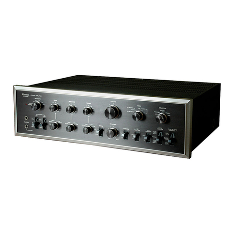
Sansui AU-9500 User manual

ANSU
A
|
OA
MODE
D’EMPLOI
OPERATING
INSTRUCTIONS
BETRIEBSANLEITUNG
~~
—AMPLIFICATEUR
STEREO
STEREO
AMPLIFIER
STEREO-VERSTARKER
SANSUI
ELECTRIC
CO.,
LTD

Tous
nos
compliments
pour
avoir
choisi
l'amplificateur
intégré
Sansui
AU-9500,
Avant
de
vous
en
servir;
nous nous
permettons
de
vous
conseiller
de
bien
lire
ce
mode
d’emploi
au
moins
une
fois,
Vous
serez
alors
en
mesure
de
connecter
et
de
régler
l'appareil
correctement
et
de
profiter
de
ses
merveilleuses
performances
pendant
de
longues
années,
PRECAUTIONS
IMPORTANTES
TABLEAU
DE
RENSEIGNEMENTS
.......2.ccceeecceeees
6,7
BRANCHEMENT
D’ENCEINTES
ACOUSTIQUES
...........
8,9
BRANCHEMENT
DE
TABLES
DE
LECTURE
.......
ie
.
10,
11
CONNEXION
D'UN
TUNER
ET
DE
MICROPHONES
,......
12,13
CONNEXION
DE
MAGNETOPHONES
.............-
cee
14,
15
COMMUTATEURS
ET
BOUTONS
DE
REGLAGE,.........
16—31
PROCESSUS
DE
REGLAGE
.......ccccceuccsceccscecs
32-37
AMELIORATION
DE
VOTRESTEREO
.........cececee
38-47
LISTE
DE
CONTROLE
RAPIDE
DES
DEFAUTS
SIMPLES
niietiw
Cowie
nace
iawn
tas
wean
Boao
CONSEILS
DE
BASE
POUR
L’ENTRETIEN
..............
52,
53
DEPANNAGE
GENERAL
............0ccececececceees
54,55
SPECIFICATIONS
.....
ata
dat
aa
heat
ae
a
rwceal
cites
eR
ae
GA
took
te
60,61

We
are
grateful
for
your
choice
of
the
Sansui
AU-9500
integrated
amplifier:
Before
you
begin
to
operate
it,
may
we
suggest
that
you
read
this
booklet
of
operating
instructions
once
carefully?
You
will
then
be
able
to
connect
and
operate
it
correctly,
and
enjoy
its
superb
performance
for
years.
Se
IMPORTANT
PRECAUTIONS
-.----
+e
e
cece
eee
eee
eeee
2-5
PANEL
INFORMATION
.---+-+---=>
Nilecbuk
OEE
See
wave
MR
6,7
CONNECTION
OF
SPEAKER
SYSTEMS
«.-+-------e+---
8,9
CONNECTION
OF
TURNTABLES
--
++
esses
eee
ee
ee
eee
10,
11
CONNECTION
OF
A
TUNER
&
MICROPHONES
.-.-.------
12,13
CONNECTION
OF
TAPE
DECKS
.------+++-+e
sree
eeeee
14,15
SWITCHES
&
CONTROLS
«+i
+e
eee
e
eee
eee
eee
cece
16—31
OPERATING
PROCEDURES
«------+-++
errr
reer
ee
eree
32—37
UPGRADING
YOUR
STEREO
«------+e
seers
ere
eres
38-47
QUICK
CHECK
LIST
OF
SIMPLE
MISTAKES
--------->-
48—51
SIMPLE
MAINTENANCE
HINTS
---------+-+>
lenses.
52,53
GENERAL
TROUBLE
SHOOTING
----+-----++e++-eees
56,57
"
SPECIFICATIONS
+--+
+--+
secrete
eee
ee
ees
ise
ee
Rays
62,
63
Wir
danken
Ihnen
fiir
die
Wahl
des
integrierten
Verstarkers
AU-9500
von
Sansui.
Bitte
lesen
Sie
vor
dem
ersten
Betrieb
diese
Betriebsan-
leitung
sorgfaltig
durch.
Dann
kGnnen
Sie
das
Gerat
richtig
anschlieRen
und
bedienen
und
seine
hervorragende
Leistung
jahrelang
genieRen.
WICHTIGE
VORSICHTSMASSNAHMEN.....,
Ne
eet
alle
2-5
SCHALTTAFELINFORMATION
.............
pies
6,7
ANSCHLUSS
VON
LAUTSPRECHERANLAGEN
.........
8,9
ANSCHLUSS
VON
PLATTENSPIELERN................
10,
11
ANSCHLUSS
VON
TUNER
UND
MIKROPHONEN
.......
12.13
ANSCHLUSS
VON
TONBANDGERATEN
.............-.
14,15
SCHALTER
UND
REGLER
..............000
ceca
aves
16-31
BEDIENUNGSVERFAHREN............ec
cae
ceceaeeee
32-37
STEREOVERBESSERUNG
......0ccccececcvevecetness
38-47
SCHNELLE
PRUFLISTE
FUR
EINFACHE
FEHLER.....
A8—51
EINFACHE
WARTUNGSHINWEISE........0..00005
0005
52,
53
ALLGEMEINE
STORUNGSSUCHE
......:.....-0+0005-
58,
59
TECHNISCHE
EINZELHEITEN
.......-
eee
eee
cerns
64,65
IMPORTANT
PRECAUTIONS
(1)
a
oie
aac
Ae
Se
bonne
circulation
d’air,
WICHTIGE
VORSICHTSMASSNAHMEN
(1)
Ne
pas
obstruer
|‘ouverture
de
ventilation
du
coffret,
Eviter
un
endroit
extrémement
chaud
ou
poussiéreux,
Si
l’appareil
est
placé
sur
une
étagére,
s’assurer
que
la
planche
soit
épaisse
et
résistante.
ees
GES
S
Be
oe
BIOS
PRUE
LG,
Du
fait
que
les
transistors
sont
sensibles
a
la
chaleur,
le
coffret
de
cet
apparei!
est
concu
pour
permettre
une
bonne
dissipation
de
la
chaleur
rayonnée
a
|’intérieur,
Ainsi,
en
cas
ot!
l'on
place
quelque
chose
sur
l’‘ouverture
de
ventilation
du
coffret,
ou
bien
si
l'appareil
est
disposé
a
l‘intérieur
d’une
boite
fermée
et
qu’on
fasse
fonctionner
|’appareil
pendant
plusieurs
heures
consécutives,
il
risque
de
tomber
en
panne,
II
faut
donc
toujours
admettre
une
circulation
d’air
suffisante
autour
de
\’appareil,
Cependant,
si
l'on
démonte
le
coffret
ou
la
plaque
de
fond
afin
d’obtenir
une
meilleure
circulation,
cela
s’avére
non
seulement
dangereux,
mais
défavorable
du
point
de
vue
performances
électriques.

To
keep
the
unit
in
top
condition
all
the
time,
observe
these
precautions:
1.
Install
the
unit
where
there
is
a
good
circulation
of
air.
2.
Do
not
obstruct
the
ventilation
opening
of
the
cabinet.
3.
Avoid
an
extremely
hot
or
dusty
place.
4.
\f
the
unit
is
placed
on
a
shelf,
be
sure
that
the
shelf
board
is
thick
and
strong.
As
transistors
are
sensitive
to
heat,
the
enclosure
of
this
unit
is
designed
to
provide
a
good
dissipation
of
the
heat
radiated
inside
this
unit.
Thus,
if
you
place
something
on
top
of
the
ventilation
opening
of
the
enclosure,
place
the
unit
inside
a
closed
box
and
operate
it
for
many
hours,
it is
possible
that
the
unit
will
break
down.
Always
try
to
provide
sufficient
circulation
of
air
around
the
unit.
But
removing
the
enclosure
or
the
bottom
plate
to
allow
better
ventilation
is
not
only
dangerous
but
undesirable
from
the
standpoint
of
electrical
perfor-
mance.
Bitte
beachten
Sie
diese
VorsichtsmaRnahmen,
um
das
Gerat
immer
in
bestem
Zustand
zu
halten:
1.
Stellen
Sie
das
Gerdt
an
einem
Platz
mit
guter
Luftzirkulation
auf.
2.
Verdecken
Sie
die
Ventilations6ffnungen
des
Gehauses
nicht.
3.
Vermeiden
Sie
besonders
heifRe
oder
staubige
Platze,
4.
Achten
Sie
bei
der
Aufstellung
des
Gerates
auf
einem
Wandbrett
0.a.
darauf,
daf&
das
Brett
dick
und
kraftig
ist.
ey
Ol
ne
Da
Transistoren
hitzeempfindlich
sind,
ist
das
Gehause
fiir
gute
Venti-
lation
entworfen.
Wenn
Sie
deshalb
die
Ventilations6ffnung
verdecken
oder
das
Gerat
langere
Zeit
in
einem
geschlossenén
Kasten
betreiben,
kann
das
Gerat
beschaddigt
werden.
Versuchen
Sie
immer
fiir
ausreichen-
de
Luftzirkulation
um
das
Gerat
zu
sorgen.
Entfernung
von
Gehause
oder
Bodenplatte
fur
bessere
Ventilation
ist
jedoch
nicht
nur
gefahrlich,
sondern
auch
vom
Standpunkt
der
elektrischen
Leistung
aus
nicht
wunschenswert.

PRECAUTIONS
IMPORTANTES
(2)
IMPORTANT
PRECAUTIONS
(2)
WICHTIGE
VORSICHTSMASSNAHMEN
(2)
Pe
=<
oe
ca
ie
Sur
les
quatre
prises
de
cour.
alt,
prévues
sur
le
panneau
arriére,
celles
marquées
‘‘SWITCHED"
sont
commandées
par
l’interrupteur
du
pan-
neau
avant.
Il
s‘avére
utile
pour
alimenter
un
composant
de
source
de
programme,
tel
qu’un
tourne-disque,
Si
|’on
maintient
l‘interrupteur
d’un
tel
composant
sur
marche,
il
devient
alors
facile
de
commander
le
courant
en
actionnant
|’interrupteur
de
cet
appareil.
Les
autres
prises
de
cour.
alt.
marquées
‘‘“UNSWITCHED”
ne
sont
pas
en
relation
avec
l'interrupteur
de
l’appareil,
Les
prises
commandées
ont
une
capacité
de
100
VA,
Celles
qui
ne
sont
PAS
COMMANDEES
ont
une
capacité
de
200
VA.
Ne
pas
connecter
un
appareil
quelconque
dont
la
puissance
dépasse
la
capacité
nominale
de
chaque
prise
car
cela
risque
d’étre
dangereux.

i
ee
Sees
ae
os
ae
_
ESR
Of
the
fou
‘SWITCHED’
are
controlled
by
the
front-panel
POWER
switch.
It
is
convenient
to
use
it
to
power
a
program
source
component,
such
as
your
turntable.
If
you
keep
the
power
switch
of
such
a
component
turned
on,
then
that
component
will
be
turned
on
and
off
as
you
operate
the
POWER
switch
of
this
unit.
The
other
AC
outlets,
marked
“UNSWITCHED’
are
not
related
to
the
unit’s
POWER
switch.
The
‘SWITCHED’
outlets
have
a
100VA
capacity.
The
‘UNSWITCHED’
ones
have
a
capacity
of
200VA.
Do
not
connect
any
equipment
whose
power
consumption
exceeds
the
capacity
of
each
of
the
outlets,
as
it
is
extremely
dangerous.
r
AC
outlets
provided
on
the
rear
panel,
the
ones
marked
it
“SWITCHED”
markierten
an
den
Netzschalter
(POWER)
auf der
Vorderseite
des
Gerates
angeschlossen.
Sie
werden
giinstig
fir
den
Anschlu&
von
Programmquellenkomponenten,
z.B.
Plattenspieler,
ver-
wendet.
Wenn
Sie
den
Netzschalter
einer
solchen
Komponente
eingeschaltet
lassen,
wird
sie
durch
den
Netzschalter
(POWER)
dieses
Gerates
ein-
und
ausgeschaltet.
Die
anderen,
mit
“UNSWITCHED”
markierten
Steckdosen
sind
unabhangig
vom
Netzschalter
(POWER)
des
Gerates.
Die
geschalteten
Steckdosen
(SWITCHED)
haben
eine
Kapazitat
von
100
VA.
Die
nicht
geschalteten
Steckdosen
(UNSWITCHED)
haben
eine
Kapazitat
von
200
VA.
Schlie&en
Sie
keine
Ausrtistung
an,
deren
Stromverbrauch
dié
Kapazitat
der
betreffenden
Steckdose
tiberschreitet,
da
dies
sehr
gefahrlich
ist.

TABLEAU
DE
RENSEIGNEMENTS
PANEL
INFORMATION
SCHALT
TAFELINFORMATION
Sponsnesrnecencenie
we,
0103
04
02
06
O05
O08
07
#42«+10
O9
11
13
12
16
17
1418
19
‘20
«15
*
Tous
les
renseignements
concernant
les
com-
*
All
switch
and
control
descriptions
are
given
on
*
Alle
Schalter-
und
Reglerbeschreibungen
sind
mutateurs
et
les
commandes
de
\'appareil
sont
pages
16-31.
Numbers
in
photo
oe
to
the
auf
den
Seiten
16
bis
31
gegeben.
Die
Nummern
indiqués
aux
pages
16.4
31.Le
numéro.des
photos
description
sequence.
“S
im
Photo
beziehen
sich
auf
die
Reihenfolge
der
se
rapporte
a
l’ordre
d’exécution
des
opérations.
Beschreibung.

~
112,
13)
SCONNECT
POWER
SUP-
bi
PLY
CORD
BEFORE
CHANG-
ING
FUSE
AND
OPENING
SYSTEM-C
>
RIGHT
+
+u
(12,
13)
(38-41)
(26,
27)(42-45)
(44-47)
*
Les
numéros
qui
sont
mis
en
*
Numbers
in
parentheses
refer
to
*
Die
Nummern
in
Klammern
beziehen
parenthéses
se
rapportent
4
la
page
on
which
description
ap-
sich
auf
die
Seite,
auf
der
die
page
qui
contient
la
description
_
pears.
Erklarung
steht.
technique.
—

BRANCHEMENT
D’ENCEINTES
ACOUSTIQUES
CONNECTION
OF
SPEAKER
SYSTEMS
Si
vous
ne
sonnestee
seulement
qu’une
paire
de
haut-parleurs
a
cet
ANSCHLUSS
VON
LAUTSPRECHERANLAGEN
appareil,
ils
peuvent
avoir
une
impédance
quelconque
entre
4
et
16
ohms,
Les
connecter
aux
bornes
SYSTEM
A,
B
ou
C
sur
le
panneau
arriére,
en
s’assurant
de
ne
pas
confondre
Jes
cables
gauche
et
droit,
les
conducteurs
plus
et
moins
aux
sorties
de
|’appareil
et
de
haut-parleur,
Mais
si
l'on
désire
connecter
deux
paires
de:
haut-parleurs
et
de
les
faire
T
. :
:
fer
Oat
diffuser
simultanément
en
actionnant
le
bouton
interrupteur/haut-
LINKS
RECHTS
parleurs
(POWER/SPEAKERS)
sur
A
+
B
ou
A_
+
C,
chaque
=
haut-parleur
doit
avoir
une
impédance
de
8
4
16
ohms,
En
utilisant
un
ROKK
XK
i
Weegee
WANs
BD
OQ?
Toonecesl
haut-parleur
avec
une
impédance
plus
faible,
il
peut
en
résulter
une
‘unica
panne
de
I|’appareil.
RXR
AX
OY
i
ae
XO
is
‘
icin
Sil
meee
ae
RY)
Ecouter
en
premier
lieu
la
reproduction
monophonique
de
n'importe
quelle
source
de
programme,
Si
les
haut-parleurs
sont
en
phase,
le
son
semblera
provenir
d’un
point
a
mi-chemin
entre
les
haut-parleurs
gauche
et
droit.
Si
le
son
_n’est
pas
directement
en
face
de
soi,
cela
signifie
alors
que
les
haut-parleurs
sont
déphasés.
Si
de
telles
conditions
se
produisent;
vérifier
une
nouvelle
fois
les
connexions
de
haut-parleurs,
Pour
y
remédier,
mettre
l'appareil
sur
arrét
puis
inverser
les
connexions
des
conducteurs
plus
et
moins
d’un
cable
de
haut-parleur.
BX
XY
[Xr
Appuyer
sur
Push
button,.
Drucken
Sie
le
bouton,
insertlead
die
Taste,
insérer
les
wires
of
schieben
Sie
conducteurs
cord,
and den
Draht
du
cordon,
release,
.
des
Kabels
et
relacher.
ein
und
las-
sen
Sie
los.

they
may
have
any
impedance
from
4
to
16
ohms.
Connect
them
to
the
SYSTEM
A,
B
or
C
terminals
on
the
rear
panel,
making
sure
not
to
confuse
the
left
and
right
cables,
plus
and
minus
leads
on
the
unit
and
speaker
ends.
But
if
you
wish
to
connect
two
pairs
of
speaker
systems
and
drive
them
simultaneously
by
turning
the
POWER/SPEAKERS
switch
to
A+B
or
A+C,
each
speaker
system
should
have
an
impedance
of
8
to
16
ohms.
Using
a
system
with
a
lower
impedance
could
result
in
a
breakdown
of
the
unit.
oS
che
First
listen
to
the
monophonic
reproduction
of
any
program
source.
If
the
speaker
systems
are
in
phase,
the
sound
will
seem
to
come
from
a
point
midway
between
the
left
and
right
speaker
systems.
If
the
sound
is
not
directly
in
front
of
you,
however,
the
speaker
systems
are
out
of
phase.
If
you
notice
this
condition,
check
the
speaker
connections
once.
To
correct
the
condition,
switch
the
unit
off
and
reverse
the
connection
of
plus
and
minus
leadwires
of
one
speaker
cable.
Wenn
Sie
nur
ein
Paar
Lautsprecheranlagen
an
das
Gerat
anschlieRen,so
kdOnnen
diese
eine
beliebige
Impedanz
zwischen
4
und
16
Ohm
haben.
SchlieRen
Sie
diese
an
die
Klemmen
SYSTEM
A,
B
oder
C
auf
der
Gerateriickseite
an
und
achten
Sie
darauf,
daf&
Sie
nicht
linke
und
rechte
Kabel,
Plus-
und
Minusleitungen
am
Geradt
und
an
den
Lautsprechern
verwechseln.
Wenn
Sie
jedoch
zwei
Paar
Lautsprecheranlagen
anschlieRen
und
sie
durch
Stellung
des
lautsprecherschalters
auf
A+B
oder
A+C
gleichzeitig
betreiben
wollen,
sollte
jede
Lautsprecheranlage
eine
Impedanz
zwischen
8
und
16
Ohm
haben.
Verwendung
einer
Anlage
mit
einer
hren.
keine
Phasenverschiebung
der
Lautsprecheranlage
vorhanden
ist,
so
scheint
der
Ton
von
einem
Punkt
in
der
Mitte
zwischen
rechter
und
liker
Lautsprecheraniage
zu
kommen.
Wenn
der
Ton
jedoch
nicht
direkt
vor
Ihnen
ist,
so
liegt
eine
Phasenverschiebung
der
Lautsprecher-
anlagen
vor.
Wenn
Sie
dies
feststellen,
so
iberpriifen
Sie
bitte
die
Lautsprecheranschliisse.
Schalten
Sie
zur
Beseitigung
dieses
Zustandes
das
Gerat
aus
und
vertauschen
Sie
die
Plus-
und
Minusleitungen
eines
Lautsprecherkabels.

10
BRANCHEMENT
DE
TABLES
DE
LECTURE
CONNECTION
OF
TURNTABLES
ANSCHLUSS
VON
PLATTENSPIELERN
BORNE
GND
GND
TERMINAL
KLEMME
GND
TOURNE-DISQUE
1
(50
kohms,
cartouche
mag-
nétique)
TURNTABLE
1
(50
kohms,
magnetic
car-
tridge)
PLATTENSPIELER
1
(50
kohms,
Magnettonab-
nehmer)
{
PHONO
[PHONO
TUNER
AUX
3
2
.TOURNE-DISQUE
2
(30,
50
ou
100
kohms,,
rég-
label,
cartouche
magnétique}
TURNTABLE
2
(30,
50
or
100.kohms,
adjust-
able,
magnetic
cartridge)
m.PLATTENSPIELER
2
COMMUTATEUR
DE
‘CHARGE
PICK-UP
PHONO-2
PHONO-2
PICKUP
LOAD
-SWITCH
(30,
50
oder
100'kOhm,
‘IMPEDANZSCHALTER
einstellbar,
Magnettonab-
‘PHONO-2
inehmer)
Le
connecter
aux
bornes
de
PHONO
1
ou
2
situées
a
I'arriére,
Pour
obtenir
les
meilleurs
résultats,
employer
une
cartouche
de
pick-up
magnétique.
Si
l'on
emploie
un
tourne-disque
avec
une
cartouche
céramique
ou
a
cristal,
le
connecter
aux
bornes
AUX,
®
Mise
a
la
terre
du
tourne-disque:
Connecter
le
fil
de
terre
du
tourne-
disque
a
cette
borne
GND.
Mais
-si
un
bruit
de
ronflement
se
fait
entendre,
\il
faut
alors
le
déconnecter.
ae
ohms
a
50
kohms
ou
100kohms
par
Je
commutateur
cde
charge
pick-up
PHONO-2
(PHONO-2
PICKUP
LOAD)
situé
sur
le
panneau
arriére.
Son
but
est
d’équilibrer
la
résistance
de
charge
de
la
cartouche
utilisée,
étant
donné
que
Jes
diverses
cartouches
possédent
des
résistances
de
charge
différentes
et
que
la
valeur
de
|l’impédance
d’un
circuit
d’entrée
phono
affecte
le
niveau
du
son
de
haute
fréquence
entre
autres.
La
plupart
des
cartouches
ont
une
résistance
de
charge
de
50
kohms,
c’est
pourquoi
l’impédance
d’entrée
du
circuit
PHONO-1
est
également
de
50
kohms.
Si
vous
avez
connecté
votre
tourne-disque
au
circuit
PHONO-2
et
que
vous
perceviez
une
légére
différence
dans
la
qualité
tonale
reproduite
en
changeant
le
commutateur
de
charge
pick-up
PHONO-2
(PHONO-2
PICKUP
LOAD),
laisser
le
commutateur
:a
la
position
de
50
kohms.

a
ts,
Bee
Connect
it
to
the
PHONO
1
or
2
terminals
on
the
rear.
For
best
resul
use
a
turntable
with
a
magnetic
pickup
cartridge.
if
you
use
a
turntable
with
a
crystal
or
ceramic
cartridge,
connect
it
to
the
AUX
terminals.
\
®
Grounding
for
turntable:
Connect
grounding
lead
of
turntable
to
this
GND
terminal.
But
if
hum
noise
is
generated
then,
disconnect
it.
The
input
impedance
of
the
PHONO-2
circuit
can
be
switched
over
from
30k2
to
50k2
to
100k2
with
the
PHONO-2
PICKUP
LOAD
switch
on
the
rear
panel.
Its
purpose
is
to
match
the
load
resistance
of
the
cartridge
in
use,
since
different
cartridges
have
different
load
resistance
values
and
the
magnitude
of
the
impedance
of
a
phono
input
circuit
affects
the
level
of
high-frequency
sound
among
other
things.
Most
cartridges
have
a
load
resistance
value
of
50kQ
which
is
why
the
input
impedance
of
the
PHONO-1
circuit
is
also
50k.
If
you
have
connected
your
turntable
to
the
PHONO-2
circuit
and
find
little
difference
in
the
reproduced
tone
quality
as
you
change
over
the
PHONO-2
PICKUP
LOAD
switch,
leave
the
switch
at
the
50k2
position.
ue
ee
Sere
UR
Ae
ee
aE
es
SchlieRen
Sie
ei
enspieler
an
die
Kilemmen
PHONO
1
oder
2
auf
der
Gerdtertickseite
an.
Verwenden
Sie
fiir
beste
Ergebnisse
einen
Plattenspieler
mit
einem
magnetischen
Tonabnehmer.
Wenn
Sie
einen
Plattenspieler
mit
einem
Kristall-
oder
Keramik-
tonabnehmer
verwenden,
so
schlieen
Sie
ihn
an
die
Klemmen
AUX
an,
@
Plattenspielererdung:
SchlieBen
Sie
die
Erdleitung
des
Plattenspielers
an
die
Klemme
GND
an.Wenn
es
jedoch,zu
Brummen
kommt,so
trennen
Sie
die
Verbindung
wieder.
Schalter
(PHONO-2
PICKUP
LOAD)
auf
der
Gerateriickseite
auf
30),
50
oder
100
kQ
eingestellt
werden.
Dies
dient
zur
Anpassung
an
den
Lastwiderstand
des
verwendeten
Tonabnehmers,
da_
verschiedene
Tonabnehmer
verschiedene
Lastwiderstandswerte
haben
und
der
Im-
pedanzwert
eines
Phono-Eingangsstromkreises
unter
anderem
den
Hochfrequenz-Tonpegel
beeinfluBt.
Die
meisten
Tonabnehmer
haben
einen
Lastwiderstandswert
von
50
kQ,
weshalb
auch
die
Eingangsimpedanz
des
Stromkreises
PHONO-1
50
kQ
ist.
Wenn
Sie
Ihren
Plattenspieler
an
den
Stromkreis
PHONO
2
angeschlossen
haben
und
beim
Umschalten
des
Schalters
PHONO-2
PICKUP
LOAD
fast
keinen
Unterschied
in
der
wiedergegebenen
Tonqualitat
hdren,
so
lassen
Sie
den
Schalter
in
der
Stellung
50
kQ.

CONNEXION
D'UN
TUNER
ET
DE
MICROPHONES
CONNECTION
OF
A
TUNER
&
MICROPHONES
ANSCHLUSS
VON
TUNER
UND
MIKROPHONEN
—
MICROPHONES
MIKROPHONE
Ce
ee)
e
Tuner
connecté
aux
entrées
AUX
{niveau
du
signal
d’entrée
réglable)
Tuner
connected
to
AUX
inputs
(input
signal
level
adjustable)
Tuner
an
AUX-Eingange
angeschlos-
sen
(Eingangssignalpegel
justierbar)
RIGHT
See
Ae
>
=
OE
ae
ee
Oe
ne
:
nee
Connecter
un
tuner
aux
bornes
TUNER
situées
sur
le
panneau
arriére,
en
utilisant
des
cables
blindés
avec
fiches
a
plots.
Si
le
tuner
ne
comporte
pas
de
contrdéle
de
niveau
de
sortie
particulier,
il
est
plus
commode
de
le
connecter
a
la
place
aux
bornes
AUX,
Etant
donné
qu’un
réglage
de
niveau
d’entrée
(indiqué
par
AUX
LEVEL
ADJ)
est
prévu
pour
le
circuit
d’entrée
AUX,
cela
permet
|‘adaptation
au
niveau
d'entrée
tuner
avec
ceux
des
autres
composants
de
source
de
pro-
gramme,
ce
qui
vous
épargne
la
peine
de
régler
le
volume
chaque
fois
qu
on
sélecteur
(SELECTOR).
a
)
no
a
ee
:
REED
-
ak
&
BRS
aoa
BAN:
A
RES
is
i
Brancher
la
fiche
de
microphone
dans
la
prise
jack
MIC
située
sur
le
Panneau
arriére,
Il
est
recommandé
d'‘utiliser
un.
microphone
de
haute
impédance
(10
k
ohms
—
50
kohms),
malgré
qu’une
faible
impédance
(600
ohms)
sera
plus
efficace
si‘l’on
veut
|‘employer
a
plusieurs
métres
de
|’amplifica-
teur.
Si
l'on
emploie
un
micro
a
faible
impédance
avec
une
faible
sortie
(tel
qu’un
microphone
du
type
dynamique
a
faible
impédance),
un
transformateur
d‘adaptation
sera
nécessaire
entre
le
cordon
de
micro-
phone
et
la
borne
de
microphone
de
l’appareil.

Connect
a
tuner
to
the
TUNER
isaninate
on
the
rear
panel,
utilizing
shielded
cables
with
pin
plugs.
If
the
tuner
has
no
output
level
control
of
its
own,
it
is
more
convenient
to
connect
it
to
the
AUX
terminals
instead.
Since
an
input
level
adjustor
(indicated
as
AUX
LEVEL
ADJ)
is
provided
for
the
AUX
input
circuit,
this
will
make
it
possible
to
match
the
tuner
input
level
with
those
of
other
program
source
components,
saving
you
the
trouble
of
adjusting
the
volume
each
time
you
change
the
Selector
switch
over.
fasart
the
mleropnene
Sider
into
the
MIC
ieee
on
ihe
rear
patel:
lt
is
recommended
to
use
a
high-impedance
(10kQ—50k2)
microphone,
although
a
low-impedance
one
(60022)
will
be
more
effective
if
you
wish
to
use
it
several
meters
away
from
the
amplifier.
!f
using
a
low-impedance
one
with
a
small
output
(such
as
a
dynamic
type
low-impedance
microphone),
you'll
need
a
matching
transformer
between
the
microphone
cord
and
the
unit's
microphone
terminal.
SchlieRen
Sie
einen
Tuner
mit
‘
abdesshirmteni
Kabel
mit
Stiftsteckern
an
die
Klemmen
TUNER
auf
der
Gerateriickseite
an.
Wenn
der
Tuner
keine
eigene
Ausgangspegelregelung
hat,
so
ist
es
bequemer,
ihn
stattdessen
an
die
Klemmen
AUX
anzuschlie&en.
Da
der
Eingangs-
stromkreis
AUX
einen
Eingangspegelregler
(AUX
LEVEL
ADJ)
hat,
kann
der
Eingangspegel
des
Tuners
auf
die
Pegel
der
anderen
Programm-
quellenkomponenten
abgestimmt
werden,
wodurch
Sie
dann
nicht
jedes
mal
die
Lautstarke
nachstellen
mUussen,
wenn
Sie
den
Wahischalter
cain
simncAll
umschalten.
Schieben
Sie
den
Mikicpnonaacker
in
die
Buchse
MIC
‘aif
‘der
Geratertickseite.
Es
wird
empfohlen
ein
Mikrophon
hoher
Impedanz
(10
kQ
bis
50
kQ)
zu
verwenden,
aber
bei
Verwendung
in
einer
Entfernung
von
einigen
Metern
vom
Gerat
ist
ein
Mikrophon
niedriger
Impedanz
(600
Q)
wirksamer.
Wenn
Sie
ein
Mikrophon
niedriger
Impedanz
mit
geringem
Ausgang
(z.B.
ein
dynamisches
Mikrophon
mit
niedriger
|mpedanz)
verwenden,
so
brauchen
Sie
einen
Anpa&transformator
zwischen
dem
Mikrophonkabel
und
den
Mikrophonklemmen
des
Gerates.

14
TAPE
DECK
1
Reglages
du
niveau
de
bande
Servent
a
ajuster
les
niveaux
des
sig-
naux
de
reproduction
quand
les
mag-
nétophone
ne
comportent
pas
de
tels
réglages,
Laisser
tourné
normalement
4
fond dans
le
sens
des
aiguilles
d'une
montre.
Tape
playback
level
adjustors
Use
to
adjust
playback
signal
levels
when
tape
deck(s)
has
no
provisions
for
such
adjustments.
Usually
leave
them
fully
turned
clockwise,
Tonbandwiedergabepegetregler
Verwendet
zur
Justierung
des
Wie-
dergabesignalpegels.
Normalerweise
vollstanding
imUhrzeigersinn
gedreht
zu
lassen.
MAGNETOPHONE
1
MAGNETOPHONE
2
TAPE
DECK
2
TONBANDGERAT
1
TONSANDGERAT
2
.CABLE
DE
REPRODUCTION/
CONNEXION
DE
MAGNETOPHONES
CONNECTION
OF
TAPE
DECKS
ANSCHLUSS
VON
TONBANDGERATEN
ENREGISTREMENT
DIN
DIN
RECORD/PLAYBACK
CABLE
DIN-KABEL
FUR
AUFNAHME/
WIEDERGABE
Ne
pas
reccorder
fa
les
platines
d’enre-
gistrement
aux
jacks
TAPE-2:
a
broche
et
au
connecteur
DIN
en
méme
temps,
Do
not
connect
tape
deck(s)
to
TAPE-2
pin
packs
and
DIN
socket
simultaneously.
SchlieBen
Sie
Tonbangerate
nicht
gleichzeitig
an
die
Stiftbuchsen
TAPE-
2
und
an
die
DIN-Buchse
an.
L’appareil
peut
s'accommoder
de
deux
magnétophones
au
plus
pour
‘enregistrement
et
la
reproduction.
Connecter
fes
bornes
d’entrée
du
magnétophone
soit
aux
bornes
TAPE
DECK
1
ou
2
REC
de
l'appareil,
et
les
bornes
de
sortie
aux
bornes
reproduction
(PLAY)
du
méme
circuit.
La
prise
DIN
fait
partie
du
circuit
magnétophone2(TAPE
DECK
2)
et
peut
étre
utilisée
si
votre
magnétophone
est
équipé
d‘une
prise
similaire.
La
construction
est
conforme
aux
normes
industrielles
allemandes
pour
permettre
!’enregistrement
et
Ja
reproduction
a
partir
d’un
simple
cable
possédant
une
fiche
spéciale
a4
5
plots
a
chaque
extrémité.
Si
l'on
désire
connecter
plus
de
deux
magnétophones,
on
pourra
connecter
le
troisieme
magnétophone
aux
bornes
d'adaptateur
a
4
canaux
(4CH
ADAPTOR).
Les
bornes
de
sortie
(OUTPUT)
ont
les
mémes
fonctions
électriques
que
les
bornes
d’enregistrement
(REC),
tandis
que
les
bornes
d’entrée
sont
équivalente
aux
bornes
de
reproduction
(PLAY),

This
unit
connects
up
to
two
tape
decks
for
recording
and
playback.
Connect
the
input
terminals
of
a
tape
deck
to
either
TAPE
DECK-1
or
2
REC
terminals
of
the
unit,
and
its
output
terminals
to
the
PLAY
terminals
of
the
same
circuit.
The
DIN
socket
is
a
part
of
the
TAPE
DECK-2
circuit
and
can
be
used
only
if
your
tape
deck
is
equipped
with
a
similar
socket.
It
is
manufactured
according
to
the
German
industrial
standard
to
permit
tape
recording
and
playback
from
a
single
cable
with
a
special
5-pin
plug
on
each
end.
Should
you
wish
to
connect
more
than
two
tape
decks,
you
may
connect
the
third
deck
to
the
4-CH
ADAPTOR
terminals.
The
OUTPUT
terminals
have
the
same
electrical
function
as
the
REC
terminals,
while
the
input
terminals
are
equivalent
to
the
PLAY
terminals.
pe
i
————
————————eeeeeeeeeeee_
An
dieses
Gerat
k6nnen
zwei
Tonbandgerate
fiir
Aufnahme
und
Wiedergabe
angeschlossen
werden.
Verbinden
Sie
die
Eingangsklemmen
eines
Tonbandgerates
mit
den
Klemmen
TAPE
DECK
1
oder
2
REC
dieses
Gerdtes
und
seine
Ausgangsklemmen
mit
den
Klemmen
PLAY
des
gleichen
Stromkreises.
Die
DIN-Buchse
ist
ein
Teil
des
Stromkreises
TAPE
DECK
2
und
kann
nur
verwendet
werden,
wenn
Ihr
Tonband-
gerat
auch
eine
DIN-Buchse
hat.
Uber
die
DIN-Buchse
k6énnen
Aufnahmen
und
Wiedergaben
iiber
ein
Kabel
mit
einem
besonderen
fiinfstiftigen
Stecker
an
beiden
Seiten
gemacht
werden.
Wenn
Sie
mehr
als
zwei
Tonbandgerate
anschlie&en
wollen,
so
kG6nnen
_Sie
ein
drittes
Gerat
an
die
Klemmen
4-CH
ADAPTOR
anschliefen.
Die
Klemmen
OUTPUT
haben
die
gleiche
Funktion
wie
die
Klemmen
REC,
wahrend
die
Eingangsklemmen
den
Klemmen
PLAY
entsprechen.

COMMUTATEURS
ET
BOUTONS
DE
REGLAGE
(1)
SWITCHES
&
CONTROLS
(1)
SCHALTER
UND
REGLER
(1)
01
Indicateur
de
puissance
(POWER
)
S‘allume
lorsque
|’on
met
sur
marche,
le
bouton
de
haut-parleurs/
interrupteur
(POWER/SPEAKERS),
et
reste
allumé
jusqu’a
ce
qu’on
le
mette
sur
arrét.
02
Bouton
de
haut-parleurs/interrupteur
(POWER/SPEAKERS)
Commande
a
la
fois
I’alimentation
et
sélectionne
les
haut-parleurs,
POWER
OFF:
Permet
de
couper
J‘alimentation
de
l'appareil.
A:
Met
l'appareil!
sous
tension
et
met
en
fonction
les
haut
-parleurs
connectés
aux
bornes
de
haut-parleur
(SYSTEM-A)
a
l’arriére.
Par
suite
du
circuit
deprotection
incorporé
de
haut-parleur/amplificateur,
le
son
ne
sera
percu
qu‘au
bout
de
quelques
secondes,
B,C:
Met
en
fonction
les
haut-parleurs
connectés
aux
bornes
de
haut-parleur
SYSTEM-B
ou
C.
A+B,
A+C:
Met
en
fonction
les
deux
paires
A
et
B,
ou
ses
deux
paires
de
haut-parleurs
A
et
C.
03
Prises
jacks
d’écouteurs
(HEADPHONE
)
Accommodent
deux
casques
écouteurs
stéréo
pour
le
contrdle
sonore
ou
l’écoute
individuelle.
La
prise
jack
supérieure
permet
d’écouter
le
son
reproduit
aussi
bien
par
les
haut-parleurs
et
le
casque
écouteur.
La
prise
inférieure
coupe
je
son
aux
haut-parleurs
permettant
I’écoute
indivi-
duelle
au
casque
ecouteur
seulement.
(SS
SSS
SSS
SSS

01
POWER
indicator
Lights
when
you
turn
on
the
POWER/SPEAKERS
switch,
and
remains
lit
until
you
turn
off
the
switch.
02
POWER/SPEAKERS
switch
Controls
both
the.power
supply
and
selection
of
speaker
systems.
POWER
OFF:
Cuts
off
power
supply
for
the
unit.
A:
Turns
on
power
supply
and
energizes
the
speaker
systems
connected
to
SYSTEM-A
speaker
terminals
on
the
rear.
Because
of
the
built-in
amplifier/speaker
protection
circuit,
sound
will
come
out
with
a
delay
of
a
few
seconds.
B,
C:
Energizes
speaker
systems
connected
to
SYSTEM-B
or
C
speaker
terminals.
A+B,
AtC:
Energizes
both
A
and
B
pairs,
or
both
A
and
C
pairs
of
speaker
systems.
03
HEADPHONE
jacks
Accommodate
two
stereo
headphone
sets
for
monitoring
or
private
listening.
The
upper
jack
lets
you.
hear
reproduced
sound
both
from
the
-
speaker
systems
and
headphone
set.
The
lower
one
cuts
off
the
sound
from
speaker
systems
for
private
listening
with
headphones
only.
01
Signallampe
(POWER)
Diese
Lampe
leuchtet
auf,
wenn
Sie
den
Netz-/Lautsprecherschalter
(POWER/SPEAKERS)
einschalten
und
bleibt
erleuchtet
bis
Sie
den
Schalter
aussthalten.
02
Netz-
/Lautsprecherschalter
(POWER/SPEAKE
RS)
Mit
diesem
Schalter
wird
das
Gerat
ein-
und
ausgeschaltet
und
die
Wah!
der
Lautsprecheranlagen
durchgefihrt.
POWER
OFF:
In
dieser
Stellung
ist
das
Gerat
ausgeschaltet.
A:
Das
Gerat
wird
eingeschaltet
und
die
an
den
Lautsprecherklemmen
SYSTEM-A
auf der
Gerdaterlickseite
angeschlossenen
Lautsprecher
werden
betrieben.
Wegen
des
eingebauten
Schutzstromkreises
fiir
Verstarker
und
Lautsprecher
dauert
es
einige
Sekunden,bis
der
Ton
zu
horen
ist.
.
B,C:
Betrieb
der
an
die
Lautsprecherklemmen
SYSTEM
B
oder
C
angeschlossenen
Lautsprecheranlagen.
A+B,
A+C:
Betrieb
der
Lautsprecheranlagenpaare
A
und
B
oder
A
und
C
gleichzeitig.
..
;
03
Kopfhérerbuchsen
(HEADPHONE)
Zwei
Paar
Stereokopfhérer
k6nnen
fur
Aufnahmetiberwachung
oder
privates
HGren
angeschlossen
werden.
Uber
die
obere
Buchse
kénnen
Sie
den
Ton
sowohl
tiber
die
Lautsprecheranlagen
als
auch
tiber
den
KopfhGrer
héren,
wahrend
bei
der
unteren
Buchse
die
Lautsprecher
fiir
individuelles
H6ren
automatisch
abgeschaltet
werden.

COMMUTATEURS
ET
BOUTONS
DE
REGLAGE
(2)
04
Commutateurs
de
filtre
(FILTER)
|
SWITCHES
&
CONTROLS
(2)
LOW:
Mettre
cé
commutateur
sur
50
Hz
ou
100
Hz
pour
éliminer
le
bruit
a
basse
fréquence
tel
que
le
ronflement
du
moteur
de
SCHALTER
UND
REGLER
(2)
tourne-disque.
Si
aucun
bruit
de
cette sorte
n’est
percu,
ne
pas
manquer
=
de
le
mettre
hors-circuit.
HIGH:
Mettre
ce
commutateur
sur
12
kHz
ou
6
kHz
pour
éliminer
le
bruit
a
haute
fréquence
tel
que
le
bruit
de
surface
d’un
disque
usé
ou
les
parasistes
produits
par
une
lampe
fluorescente
mélangés
aux’
émissions
de
radio.
05
Réglage
de
tonalité
grave
(BASS)
L‘utiliser
de
la
méme
maniére
que
le
réglage
de
tonalité
aigué
pour
ajuster
|’intensité
du
son
a
basse
fréquence
(grave)
a
raison
de
3
dB
par
déclic.
06
Sélecteur
de
tonalité
grave
(BASS)
Permet
a
l'utilisateur
de
choisir
la
fréquence
en-dessous
de
laquelle
le
réglage
de
tonalité
grave
(BASS)
fonctionne:
DEFEAT:
Met
hors-circuit
le
réglage
de
tonalité
grave
(BASS),
et
per-
met
a
l’'amplificateur
d’amplifier
les
signaux
de
basse
fréquence
juste
comme
ils
se
présentent
dans
la
source
de
programme.
150
Hz:
Le
réglage
de
tonalité
(BASS)
grave
agira
sur
le
son
en
dessous
de
150
Hz.
300
Hz:
Le
réglage
de
tonalité
grave
(BASS)
agira
sur
le
son
en-dessous
de
300
Hz.
600
Hz:
Le
réglage
de
tonalité
grave
(BASS)
agira
sur
le
son
en-dessous
de
600
Hz.
Other manuals for AU-9500
1
Table of contents
Other Sansui Amplifier manuals

Sansui
Sansui AU-G55X User manual

Sansui
Sansui AU-7700 User manual

Sansui
Sansui 2000X User manual

Sansui
Sansui 350A User manual

Sansui
Sansui AU-11000 User manual

Sansui
Sansui AU-777 User manual

Sansui
Sansui CA-2000 User manual

Sansui
Sansui 4000 User manual

Sansui
Sansui A-9 User manual

Sansui
Sansui AU-999 Troubleshooting guide

Sansui
Sansui EIGHT User manual

Sansui
Sansui 1000A Troubleshooting guide

Sansui
Sansui A-909 User manual

Sansui
Sansui AU-517 User manual

Sansui
Sansui AU-D33 User manual

Sansui
Sansui AU-999 Troubleshooting guide

Sansui
Sansui AU-505 Instruction and safety manual

Sansui
Sansui A-1100 User manual

Sansui
Sansui 5000X User manual

Sansui
Sansui AU-919 User manual