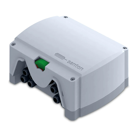
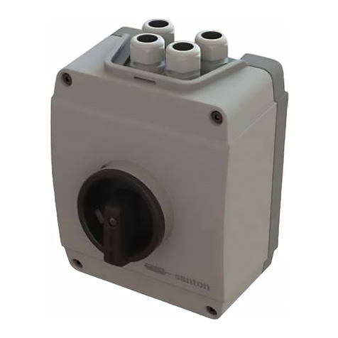
Santon FSS-A300-FU User manual

INSTALLATION MANUAL
INSTALLATIEHANDLEIDING
INSTALLATIONSHANDBUCH
MANUEL D’INSTALLATION
MANUAL DE INSTALACIÓN
MANUALE DI INSTALLAZIONE
EN
DE
FR
ES
IT
NL
THE SANTON
FIREFIGHTER
SAFETY
SWITCH
FOR PHOTOVOLTAIC INSTALLATIONS

FIREFIGHTER SAFETY SWITCH
SAFETY PRECAUTIONS
2 3
Important safety precautions
Attention! Components in the installations are exposed to high voltages and currents. Follow these instructions carefully in order to
reduce the risk of re or electric shock.
The following regulations and standards are considered applicable and mandatory to read prior to the installation of electrical equipment:
• International Standards: IEC 60364-7-712 Electrical installations of buildings – Requirements for special installations or locations – Solar
Photovoltaic (PV) power supply systems
• MIS3002: Microgeneration Installation Standard - requirements for contractors undertaking the supply, design, installation, set to work
commissioning and handover of solar photovoltaic (PV) microgeneration systems
• Local building regulations and local legislation at the time of installation
• Guidelines for lightning and overvoltage protection
Note!
• It is essential to uphold the limits for voltage and current in all possible operating conditions (see page 7; ‘Technical Data’).
Also keep in mind the literature on correct dimensioning and sizing of cabling and components.
• The installation of these devices may only be performed by certied technical personnel.
• All the installation works should be tested in accordance with relevant local legislation at the time of installation.
Importantes Medidas De Seguridad
¡Atención! Los componentes de la instalación están expuestos a corrientes de alto voltaje. Siga atentamente estas instrucciones para
reducir el riesgo de incendio o descarga eléctrica.
Hay que tener en cuenta los siguientes reglamentos y normas. Léalos detenidamente antes de instalar el equipo eléctrico:
• Normas internacionales: IEC 60364-7-712 Instalaciones eléctricas en edicios – Requisitos para las instalaciones y emplazamientos
especiales – Sistemas de alimentación de energía solar fotovoltaica
• Normas urbanísticas locales y legislación local en el momento de la instalación
• Pautas de protección contra rayos y sobretensiones
Nota!
• Es fundamental que respete los límites de voltaje y corriente en todas las condiciones de funcionamiento posibles (véase páginas 7;
“Datos técnicos”).Tenga en cuenta la información sobre el tamaño y dimensionamiento correctos de cables y componentes.
• La instalación de estos dispositivos solo debe llevarse a cabo por personal técnico cualicado.
• Todos los trabajos de instalación deben comprobarse de acuerdo con la legislación local pertinente en el momento de la instalación.
Wichtige Sicherheitsvorkehrungen
Achtung! Bauteile der Anlagen werden hohen Spannungen und Strömen ausgesetzt. Halten Sie sich an diese Anweisungen, um das
Risiko eines Feuers oder Stromschlags zu minimieren.
Es gelten die folgenden Vorschriften und Normen. Diese müssen durchgelesen werden, bevor elektrische Geräte installiert werden:
• Internationale Standards: IEC 60364-7-712 Elektrische Anlagen von Gebäuden - Anforderungen bei besonderen Anlagen oder Standorten
- Solar Photovoltaik-(PV) Stromversorgungssysteme
• Lokale Vorgaben: - DIN VDE 0100 - Errichten von Niederspannungsanlagen
- VDI 6012 - Dezentrale Energiesysteme im Gebäude, Photovoltaik
- BGV A1 - Allgemeine Vorschriften
- BGV A2 - Elektrische Anlagen und Betriebsmittel
• Richtlinien für den Blitz- und Überspannungsschutz
Anmerkung!
• Die angegeben Grenzen für Spannung und Strom sind unbedingt in allen möglichen Betriebszuständen einzuhalten (siehe Seite 7;
Technische Angaben“).Beachten Sie bitte auch die Fachliteratur über die richtige Auslegung und Dimensionierung von Kabeln und
Komponenten.
• Die Installation dieser Geräte darf nur von entsprechend geschultem Fachpersonal durchgeführt werden.
• Die gesamten Installationsarbeiten müssen anhand der entsprechenden lokalen Vorschriften zum Zeitpunkt der Installation überprüft
werden.
Important safety precautions
Attenzione! I componenti delle installazioni sono esposti a tensioni e correnti elevate; seguite scrupolosamente queste istruzioni per
ridurre il rischio di incendi ed elettrocuzioni.
Segue l’elenco delle norme e dei regolamenti pertinenti, che dovete leggere prima di installare l’apparecchiatura elettrica:
• Norme internazionali: IEC 60364-7-712 Installazioni elettriche degli edici – Regolamentazioni per installazioni e aree speciali – Sistemi di
alimentazione fotovoltaici
• Normative locali sugli edici e legislazione vigente al momento dell’installazione
• Istruzioni di protezione contro i fulmini e le sovratensioni
Nota!
• È essenziale rispettare i limiti di tensione e corrente in tutte le possibili condizioni di funzionamento (vedere le pagine 7, “Dati tecnici”).
Dovete inoltre attenervi anche alla documentazione in materia di corretto dimensionamento dei cavi e dei componenti.
• L’installazione di questi dispositivi deve essere eseguita esclusivamente da personale tecnico addestrato.
• Tutte le opere di installazione devono essere collaudate in conformità alla legislazione vigente al momento dell’installazione.
Mesures de sécurité importantes
Attention! Les éléments des installations sont exposés à de hautes tensions et intensités. Veuillez suivre attentivement ces instructions
pour réduire le risque d’incendie ou d’électrochoc.
Les réglementations et normes suivantes s’appliquent. Il faut les lire avant l’installation du matériel électrique :
• Normes internationales : IEC 60364-7-712 : Installations électriques des bâtiments – Règles pour les installations et emplacements
spéciaux – Alimentations photovoltaïques (PV) solaires
• Réglementations locales et législation locale concernant les bâtiments en vigueur au moment de l’installation
• Directives sur l’éclairage et la protection contre la surtension
Remarque!
• Il faut impérativement respecter les limites imposées de tension et d’intensité dans toutes les conditions d’exploitation (voir page 7,
‘Caractéristiques techniques’). Il convient aussi de tenir à l’esprit les publications concernant le dimensionnement et la détermination des
tailles des câblages et des éléments des installations.
• L’installation de ces dispositifs doit être strictement réservée à un personnel technique ayant suivi une formation adaptée.
• Il faut tester le fonctionnement de tous les éléments de l’installation conformément à la législation locale en vigueur au moment de
l’installation.
Belangrijke voorzorgsmaatregelen
Let op! Componenten in de installatie staan blootgesteld aan hoge spanning en stroomsterktes. Volg deze instructies met zorg op om het
risico op brand of een elektrische schok te verminderen.
De volgende regels en normen zijn van toepassing. Het is belangrijk deze door te lezen alvorens de elektrische apparatuur te installeren:
• Internationale normen: IEC 60364-7-712: Elektrische installaties van gebouwen: bepalingen voor bijzondere installaties of locaties -
fotovoltaïsche (PV) voedingssystemen
• Lokale voorschriften voor gebouwen en lokale wetgeving op het moment van installatie
• Richtlijnen voor bescherming tegen bliksem en overspanning
Opmerking!
• Het is essentieel om de grenzen voor spanning en stroomsterkte in alle mogelijke bedrijfssituaties te handhaven
(zie pagina 7, ‘Technische gegevens’). Bekijk ook de literatuur over de juiste maten en afmetingen van kabels en componenten.
• De installatie van deze apparaten mag alleen worden uitgevoerd door geschoold technisch personeel.
• Alle werkzaamheden ten behoeve van de installatie dienen getest te worden in overeenstemming met de relevante lokale wetgeving ten
tijde van de installatie.
EN ES
DE IT
FR NL

General notice for users
• Changes or modications not explained/approved in this manual voids your authority to operate this equipment.
• Santon shall not be held responsible for any damage caused due to incorrect installation of the product and/or the
misunderstanding of this manual.
• Santon reserves the right to make any modication to this manual or the information contained herein at any time
without notice.
• No design data such as sample pictures provided in this manual may be modied or duplicated except for the purpose
of personal use.
• To ensure the recycling of all possible materials and proper disposal treatment of components, please return the
product to Santon at end-of-life.
• Check the system regularly (once per 3 months) on faults.
Algemene opmerkingen voor de gebruiker
• Aanpassingen of modicaties welke niet vermeld/goedgekeurd worden in deze handleiding zullen ertoe leiden dat de
bevoegdheid tot het bedienden van deze apparatuur verloren wordt.
• Santon kan niet aansprakelijk worden gesteld voor het oplopen van schade of letsel door incorrecte installatie en/of het
verkeerd interpreteren van deze handleiding.
• Santon behoudt zich het recht voor om wijzigingen aan te brengen in deze handleiding of de hierin opgenomen
informatie op elk gewenst moment zonder verdere kennisgeving.
• Alle ontwerpgegevens, zoals de voorbeelden in deze handleiding, mogen niet worden gewijzigd of gedupliceerd,
behalve ten behoeve van eigen gebruik.
• Om de recycling van alle mogelijke materialen en een goede afvoer van de componenten te garanderen, dient het
product aan het einde van de levensduur aan Santon te worden geretourneerd.
• Controleer het systeem regelmatig (eenmaal per 3 maanden) op fouten.
Aviso general para los usuarios
• Todo cambio o modicación que no esté explicado/aprobado en este manual puede anular su autorización para operar
este equipo.
• Santon no será responsable de ningún daño ocasionado debido a la instalación incorrecta del producto por no
comprender adecuadamente este manual.
• Santon se reserva el derecho de realizar, sin previo aviso, cualquier modicación de este manual o de la información
contenida en él.
• Cualquiera de los datos de dise‚o incluidos en este manual, tales como los dibujos de muestra , no pueden ser
modicados ni duplicados, excepto para uso personal.
• Para asegurar el reciclaje de todos los materiales posibles y la eliminación apropiada de los componentes, sírvase
devolver el producto a Santon al nal de su vida útil.
• Compruebe periódicamente (una vez cada 3 meses) el sistema para ver si existen fallos.
Avviso generale per gli utenti
• Qualsiasi variazione o modica non descritta/autorizzata nel presente manuale potrebbe annulare l’autorizzazione
all’uso dell’apparecchio.
• Santon declina qualsiasi responsabilità per danni causati da un’installazione non conforme del prodotto e/o dalla
mancata comprensione del presente manuale.
• Santon si riserva il diritto di apportare eventuali modiche al presente manuale o alle informazioni ivi descritte in
qualsiasi momento e senza preavviso.
• Non è consentito modicare o riprodurre le immagini di progetto di esempio riportate nel presente manuale se non per
scopi di uso personale.
• Al ne di garantire il riciclaggio di tutti i materiali e lo smaltimento corretto del componente, una volta raggiunto il
termine del ciclo di vita del prodotto si prega di restituirlo a Santon.
• Controllare periodicamente l’impianto (una volta ogni 3 mesi) alla ricerca di eventuali anomalie.
FIREFIGHTER SAFETY SWITCH
GENERAL NOTICE
Allgemeine Hinweise für Benutzer
• Veränderungen oder Modikationen, die in diesem Handbuch nicht erklärt oder zugestanden werden, erlischt die
Berechtigung zum betrieb dieses Gerätes genehmigt.
• Santon ist nicht für Schäden haftbar, die durch die fehlerhafte Installation des Produkts und/oder der Fehlinterpretation
dieses Handbuches entstehen.
• Santon behält sich das Recht vor, jederzeit und ohne vorherige Ankündigung Veränderungen an diesem Handbuch
und den darin enthaltenen Informationen vorzunehmen.
• Sämtliche Designdaten, wie etwa Beispielsbilder, die in diesem Handbuch zur Verfügung gestellt werden, dürfen nicht
verändert oder vervielfältigt werden, es sei denn, für den persönlichen Gebrauch.
• Bitte senden Sie das Produkt am Ende dessen Lebenszyklus zurück an Santon, um das Recyceln aller in Frage
kommenden Materialien und die fachgerechte Entsorgung von Abfällen zu garantieren.
• Überprüfen Sie das System regelmäßig (einmal pro 3 Monate) auf Fehler.
Avis général aux utilisateurs
• Les changements ou modications non expliqués/approuvés dans ce manuel peuvent annuler votre droit à faire
fonctionner cet équipement.
• Santon ne peut être tenu responsable de tout dommage dû à une installation incorrecte du produit et/ou la mauvaise
compréhension de ce manuel.
• Santon se réserve le droit d’apporter des modications, à tout moment et sans préavis, à ce manuel ou aux
informations qu’il comporte.
• Toutes les données de fabrication telles que les photos d’échantillon fournies dans ce manuel ne peuvent être
modiées, ni reproduites sauf pour votre usage personnel.
• Veuillez retourner le produit à Santon en n de vie an que tous les matériaux pouvant être recyclés le soient et que
les composants soient convenablement éliminés.
• Vériez le système régulièrement (une fois par 3 mois) pour vous assurer de la détection des défauts.
45
EN ES
DE IT
FR NL

FIREFIGHTER SAFETY SWITCH
CONTENT TECHNICAL DATA (IEC)
FSS-A300-FU
• Motor driven DC-disconnect switch in aluminium
enclosure
• 12x cable glands M16 for string wiring
• 2x cable glands M20 for control wiring
• Fireghter safety switch manual
FSS-A300-FTU
• Motor driven DC disconnect switch in aluminium
enclosure (pre-wired on spring terminals)
• 12x cable glands M16 for string wiring
• 2x cable glands M20 for control wiring
• Fireghter safety switch manual
FSS-A300-FRU
• Motor driven DC disconnect switch in aluminium
enclosure (pre-wired with retrot cables)
• 12x cable glands M16 for string wiring
• 2x cable glands M20 for control wiring
• Fireghter safety switch manual
FSS-B5
• Operating panel in robust plastic enclosure
• 2x cable glands M20 for power wiring
• Fireghter safety switch manual
FSS-B6
• Operating panel on metal plate
(intended for ush mounting)
• Fireghter safety switch manual
Fireghter switch FSS-A300-F*U-25A FSS-A300-F*U-32A
Nom. Voltage 1000VDC 1000VDC
Max. current/voltage 10A/1000V, 16A/850V, 25A/800V 16A/1000V, 25A/850V, 32A/750V
Switch version 6 pole, positions 0-1-0-1 6 pole, positions 0-1-0-1
Number. of strings 1 to 3 1 to 3
Protection degree / level IP65 / class II IP65 / class II
Ambient temperature range -20°C to +50°C -20°C to +50°C
Weight Approx. 4 kg Approx. 4 kg
CE certication EN 60947 part 1 + 3 EN 60947 part 1 + 3
DC switch disconnect according to EN 60947-1, DIN VDE 0100-712 EN 60947-1, DIN VDE 0100-712
Number of cycles >10000 >10000
Number of cycles under load (DC21) >1500 >1500
Operating panel FSS-B5 FSS-B6
Voltage 24VDC ± 10% 24VDC ± 10%
Current 0.3A per switch 0.3A per switch
Number of FSS switches Max. 15 Max. 15
Protection degree / level IP65 / class II IP20 / class II
Ambient temperature range -20°C to +50°C -20°C to +50°C
Weight Approx. 1kg Approx. 1kg
CE certication EN 60947 part 1 + 3 EN 60947 part 1 + 3
Recommended cable diameters 1-8 FSS 9-15 FSS
Distance between operating panel and switces
0m - 50m 2.5 mm² 4 mm²
50m - 100m 4 mm² 6 mm²
100m - 200m 6 mm² 10 mm²
Recommended Power supply unit(s) 1-8 FSS switches 9-15 FSS switches
Voltage / current (max.) 24VDC ± 10% / 2.5A 24VDC ± 10% 5A
Power (max.) 60W 120W
Manufacturers: Power Part number Power Part number
Omron 60W S8VS-06024 120W S8VS-12024
Phoenix-contact 60W 2868651 120W 2866750
Siemens 60W 6EP1332-2BA10 120W 6EP1333-2AA01
Note:
Santon is not responsible for the correct part number of the mentioned manufacturer, please contact the
manufacturer for correct ordering information.
6 7

!
!
!
FIREFIGHTER SAFETY SWITCH
INSTALLATION MANUAL
1.
Installation requirements
Installationsanforderungen
Conditions requises pour l’installation
Requisitos de instalación
Requisiti di installazione
Installatiebenodigdheden
2.
Remove switch enclosure lid
Entfernen Sie den Deckel vom Schaltergehäuse
Ôtez le couvercle du boîtier de l’interrupteur
Quite la tapa de la envolvente del interruptor
Rimuovere il coperchio dell’alloggiamento dell’interruttore
Verwijder het deksel van de schakelaarbehuizing
3.
Mount the switch enclosure on the wall
Montieren Sie den Boden des Gehäuses an der Wand
Fixez le boîtier de l’interrupteur au mur
Instale la envolvente del interruptor en la pared
Montare l’alloggiamento dell’interruttore alla parete
Bevestig de bodem van de behuizing aan de wand
4.
Wire the control signal terminals and the grounding
Schließen Sie die Steuerleitungen an und die Erdung
Câblez les bornes du signal de commande et la mise à la terre
Cablear los terminales de las se€ales de control y tierra
Cablare i terminali del segnale di controllo e la messa a terra
Bedraad de kroonsteen met de stuurstroomkabels en sluit de aarde aan
!
1
2
3
4
5
6
7
Max. M8 (4x)
4x M8
M8M4
Max. 2.5mm²
panels inverter
8 9
!
5. (Basic)
Wire the string cables to the switch
Schließen Sie die Gleichstromkabel an den Schalter an
Branchez les câbles de chaîne à l’interrupteur
Conecte los cables en serie al interruptor
Collegare i conduttori piatti all’interruttore
Bedraad de zonnepaneelkabels op de schakelaar
6. (Express)
Wire the string cables to the spring terminals
Schließen Sie die Gleichstromkabel an den Federzugklemmen an
Branchez les câbles de chaîne aux bornes à ressort
Conecte los cables en serie al interruptor
Collegare i conduttori piatti all’interruttore
Bedraad de zonnepaneelkabels op de veerdrukklemmen
7. (Retrot)
Attach PV connectors to the string cables
Montieren Sie die PV Steckerverbinder an den Gleichstromkabeln
Fixez les connecteurs PV aux câbles de chaîne
Connecte los conectores a los cables en serie
Collegare i connettori FV ai conduttori piatti
Verbind de PV connectoren aan de zonnepaneelkabels
FSS-A300 FU
FSS-A300-FTU
FSS-A300-FRU
± 10mm
Max. 6mm²
Max. 1.7Nm
8.
Close the switch enclosure
Montieren Sie wieder den Gehäusedeckel
Fermez le boîtier de l’interrupteur
Cierre la envolvente del interruptor
Chiudere l’alloggiamento dell’interruttore
Sluit de schakelaarbehuizing
Max. 17Nm
!
9.
Remove the control panel enclosure lid
Entfernen Sie den Gehäusedeckel vom Bedientableau
Ôtez le couvercle du boîtier du tableau de commande
Quite la tapa de la envolvente del panel de control
Rimuovere il coperchio dell’alloggiamento del pannello di controllo
Verwijder het deksel van het bedieningspaneel
FSS-B5
10.
Mount the control panel enclosure on the wall
Montieren Sie den Boden des Gehäuses an der Wand
Fixez le boîtier du tableau de commande au mur
Instale la envolvente del panel de control en la pared
Montare l’alloggiamento del pannello di controllo alla parete
Bevestig de bodem van de behuizing aan de wand
FSS-B5
Max. M4 (2x)
4x M4
4x M8

FIREFIGHTER SAFETY SWITCH
INSTALLATION MANUAL
10 11
11. (optional)
Prepare the control panel mounting
Bereiten Sie die Montage des Bedientableaus vor
Préparez le montage du tableau de commande
Prepare el montaje del panel de control
Preparare il montaggio del pannello di controllo
Bereid de montage van het bedieningspaneel voor
FSS-B6
12.
Wire the control signal cable to the circuit board
Schließen Sie die Steuerleitung an
Câblez le circuit imprimé
Realice del cableado de la placa del circuito
Collegare la piastra per il circuito stampato
Bedraad de printplaat met de stuurstroom kabel
13.
Connect the power supply to the circuit board
Schließen Sie die Schaltplatte an die Stromversorgung an
Branchez l’alimentation du circuit imprimé
Conecte la fuente de alimentación a la placa del circuito
Collegare l’alimentazione alla piastra per il circuito stampato
Bedraad de stroomvoorziening op de printplaat
14. (optional)
Connect the external alarm
Schließen Sie den externen Alarm an
Raccordez l’alarme externe
Conecte la alarma externa
Collegare l’allarme esterno
Bedraad het externe alarm
Max. M4 (4x)
104
110
45
15.
Close the operating panel enclosure
Montieren Sie wieder den Gehäusedeckel
Fermez le boîtier du panneau de commande
Cierre envolvente del panel de mando
Chiudere l’alloggiamento del pannello di controllo
Sluit het de behuizing van het bedieningspaneel
16.
Connect the power supply to the power grid
Verbinden Sie die Stromversorgung mit dem Energienetz
Branchez l’alimentation au réseau électrique
Conecte la fuente de alimentación a la red eléctrica
Collegare l’alimentazione alla piastra a griglia di alimentazione
Verbind de stroomvoorziening met het net
18. (activation)
Insert the key into the push button to activate the system
Stecken Sie den Schlüssel in den Taster ein, um das System zu aktivieren
Insérez la clé dans le bouton-poussoir pour activer le système
Para activar el sistema, coloque la llave en el pulsador
Attivare il sistema inserendo la chiave nel pulsante
Steek de sleutel in de drukknop om het systeem te activeren
19. (activation)
Release the push button with the key, the red LED will blink
Lösen Sie den Taster mit Hilfe des Schlüssels, die rote Kontrollleuchte blinkt
Déclenchez le bouton-poussoir avec la clé, le voyant rouge clignote
Libere el pulsador con la llave; la luz roja parpadeará
Sbloccare il pulsante con la chiave, la spia rossa lampeggia
Ontgrendel de drukknop met de sleutel, de rode LED zal knipperen
20. (activation)
Remove the key from the push button
Ziehen Sie den Schlüssel vom Taster ab
Retirez la clé du bouton-poussoir
Quite la llave del pulsador
Recuperare la chiave dal pulsante
Verwijder de sleutel uit de drukknop
17.
Wait at least one minute, in order to charge the UPS
Warten Sie mindestens eine Minute, um die USV zu laden
Attendez au moins une minute pour charger l’onduleur
Espere un minuto como mínimo para cargar el UPS
Attendere almeno un minuto per la ricarica del gruppo di continuità
Wacht minstens één minuut, om de UPS op te laden
Max. 2Nm
Min. 1 min.
!
!
4x M4
Max. 2.5mm²

154
154
108
340
226
340
130
43
402
130
130
114
114
280
156
133
130
74
FIREFIGHTER SAFETY SWITCH
INSTALLATION MANUAL
FSS-A300-F*U
FSS-B5
FSS-B6
12 13
25.
Repeat steps 18 & 19 to reactivate the system
Wiederholen Sie Schritt 18 & 19, um das System zu reaktivieren
Répétez les étapes 18 et 19 pour réactiver le système
Para reactivar el sistema, repita los pasos 18 y 19
Per riattivare il sistema ripetere i passaggi 18 e 19
Herhaal stappen 18 & 19 om het systeem te reactiveren
24.
When steps 19 till 23 were not successfull, see the troubleshooting list on page 15
Wenn die Schritte 19 bis 23 nicht erfolgreich waren, nden Sie der Liste zur Fehlerbehebung auf Seite 17
Si les étapes 19 à 23 n’ont pas marché, allez voir la liste de dépannage à la page 19
Si los pasos 19 a 23 no fueron exitosos, consulte la lista de solución de problemas en la página 21.
Se i passaggi 19-23 non restituiscono i risultati descritti consultare la risoluzione dei problemi a pagina 23
Als de stappen 19 tot 23 niet succesvol waren, zie dan de lijst met oplossingen op pagina 25
21. (test)
Press the push button to test the disconnection of the system
Drücken Sie den Taster, um das Abschaltung des Systems zu testen
Pour tester le débranchement du système, appuyez sur le bouton-poussoir
Para probar la desconexión del sistema, presione el pulsador
Vericare la disconnessione del sistema premendo il pulsante
Druk op de knop om het afschakelen van het systeem te testen
22. (test)
The red LED will blink
Die rote Kontrollleuchte fängt daraufhin an zu blinken
Le voyant rouge clignote
La luz roja parpadeará
La spia rossa lampeggia
De rode LED zal knipperen
23. (test)
When the system is disconnected and installed correctly, the green LED will be lit
Wenn das System abgeschaltet und korrekt installiert ist, leuchtet die grüne Kontrollleuchte
Lorsque le système est débranché et installé correctement, le voyant vert s’allume
Cuando el sistema esté desconectado e instalado correctamente, se encenderá la luz verde
Quando il sistema viene scollegato e installato correttamente, la spia verde si accende
Wanneer het systeem afgeschakeld en correct geïnstalleerd is,
zal de groene LED branden
DIMENSIONS

FIREFIGHTER SAFETY SWITCH
USER INSTRUCTIONS
Intended use
The Fireghter safety switch (FSS) has been especially developed as an additional device for direct
current (DC) photovoltaic installations. The motor driven DC disconnect switch is made to withstand a
continuous current ow at a maximum of 25A at a string voltage of 750 VDC, or 16A at a string voltage
of 1000 VDC.The DC disconnect switch is used to disconnect the connected strings of the installation
in case of an emergency situation, either under load or no-load situations. Such an emergency situation
could be in case of re.
NOTE: The switch enclosure and/or the operating panel enclosure may not be installed in direct sunlight
or be in direct contact with (continuous) ingress water.
Fireghter Safety Switch
The switch enclosure needs to
be placed as close to the string
entry of the building as possible
and may be placed in outdoor
situations when needed. Due
to its enclosure, the switch is
protected against external
inuences like dust and
moisture. The whole set-up
is conforms to IP65. This will
make it resistant to direct water
jets from all directions.
Operating Panel
The reghter must be able to safely
disconnect the photovoltaic installation
which is in operation and make sure
the installation is completely switched
off before proceeding further. To aid the
reghters, the operating panel must
be used in case of emergency to switch
off the installation. The operating panel
therefore needs to be placed in an easy
to access location. The operating panel
must be visible for re ghters so they
can see the status and instantly act in
case of an emergency.
Junction Box (optional)
Combining individual string
cables into lead cables to the
inverter. Can optionally include
fuses, overvoltage protection
and arc fault detection.
Inverter
String or lead cables join into the inverter
which provides the connection to the external
power grid.
External re alarm (optional)
An external alarm can also be
connected to the Operating
Panel and thereby activate
the disconnection of the safety
switches.
Operation
Powering up:
When all connections are made according to the specications in this manual, the operating panel will
show a green LED indicating that all connected switches are in a disconnected state OFF. This indicates
a safe situation for the reghter. When you release the key operated push button, the system will send
commands to turn all connected switches ON. If this is working correctly, the red (or white) LED will blink
momentarily and burn continuously when the command is executed. The red (or white) LED indicates that
the switches are ON and thus an unsafe situation for the re ghters.
NOTE: The key used to turn the switches ON must be kept separate from the operating panel and only
authorised personnel are allowed to use this.
Normal operation:
Pressing the push button will instruct the switches to break the connection between solar panels and the
inverter. Releasing the push button with the key will instruct the connected switches to make the
connection between solar panels and the inverter.
Special operation:
Power down:
If there is going to be a power down situation, the operating panel will no longer provide the
signal commands to the connected switches after approximately 10-15 seconds.
Connection loss:
If one of the connected switches looses contact with the operating panel, this switch will also
break the connection between the solar panels and the inverter.
Testing the system:
It is considered mandatory to test the reghter safety switches at least once every three
months. This is to ensure the system is still fully functional.
Fault situation:
When the operating panel cannot determine that all switches are in the same position or if not all switches
have changed position within 15 seconds, both the LED’s will blink and a buzzer will sound until a reset
has been performed.
The switches need to be checked and all placed in the same position to ensure the operating panel can
be reset. The fault mode can be reset by pressing the push button and releasing it with the key 2 times
within 3 seconds. This will reset the electronics and start the state check of all connected switches.
Checklist Fault situation:
• Check Voltage at the switch; this must be 24VDC (± 5%)
• Check switch positions; these must ALL be ON or OFF
• Check wiring of all switches; these must be according to the “Wiring Schematics” on pages 26 and 27
• Check wiring of the Operating Panel
• Check Voltage and Current of the power supply: see “Technical Data” on page 7
If a fault situation keeps occurring please contact Santon for more information:
support@santonswitchgear.com
14 15
EN

FEUERWEHR-SICHERHEITS-SCHALTER
BETRIEBSANLEITUNG
Verwendungszweck
Der Feuerwehr Sicherheitsschalter (FSS) wurde speziell als zusätzliche Sicherheitsschaltereinheit für
photovoltaische Anlagen mit Gleichstrom (DC) entwickelt. Der DC-Lasttrennschalter hält einem
dauerhaftenStromuss bis maximal 25A bei 750VDC und einer Strangspannung von maximal 1000VDC
bei 16A stand. Der DC-Lasttrennschalter wird verwendet um im Notfall die verbundenen Stränge
zwischen Generator(Module) und Wechselrichter motorisch zu unterbrechen, dies auch unter Last
(maximaler Kurzschlussstrom bzw. maximale Leerlaufspannung). Solch ein Notfall entsteht zum Beispiel
im Falle eines Feuers. Ein Feuerwehrmann muss eine photovoltaische Anlage, sicher abschalten
(galvanische Trennung) und garantieren, dass die Anlage vollständig abgeschaltet und das Gebäude
DC-Spannungsfrei ist.
BEACHTEN: Das Schaltergehäuse und/oder das Bedientableau darf nicht dauerhaft im direkten
Sonnenlicht oder in direktem Kontakt mit (ständig) eintretendem Wasser angebracht werden.
Bedienung
Inbetriebnahme:
Wenn alle Verbindungen hergestellt sind, wie im Handbuch beschrieben, soll die grüne LED am
Bedientableau leuchten. Das zeigt an, dass das Gebäude DC-Spannungsfrei ist, alle angeschlossen
DC-Freischalter sind freigeschaltet. Wenn mit dem Schlüssel der Not-Aus „entriegelt“ wird, wird das
Bedientableau sofort alle angeschlossen Schalter einschalten. Die rote (oder weiße) LED blinkt, solange
die Motoren laufen. Sobald alle angeschlossenen Schalter in ON-Position sind leuchtet (Dauerlicht) die
rote (oder weiße) LED.
ACHTUNG: Das Einschalten der FSS Schalter, darf nur durch autorisiertes Fachpersonal erfolgen.
Deshalb muss der Schlüssel getrennt vom Bedientableau aufbewahrt werden.
Normal Betrieb:
Wenn ein Notfall eintritt = Betätigung des Druckknopfes, sendet das Bedientableau ein Signal an alle
angeschlossenen Schalter mit dem Auftrag, die Verbindung zwischen Solargenerator und Wechselrichter
zu unterbrechen (AUS). Mit dem Schlüssel kann die Anlage wieder bewusst eingeschaltet werden.
Die Verbindung zwischen Solargenerator und Wechselrichter wird wieder geschlossen (EIN) und
zurückgemeldet.
Spezial Betrieb:
Stromausfall:
Wenn die Stromversorgung wegfällt, wird die Ansteuerung für die Schalter nicht mehr durch
das Bedientableau versorgt. Die Notstromversorgung im Schaltergehäuse übernimmt dann die
Ansteuerung. Nach ca. 10 sec. bekommen alle angeschlossenen Schalter einen AUS-Befehl.
Die String-Verbindungen zwischen Solargenerator und Wechselrichter werden unterbrochen (AUS).
Verbindungsunterbrechung:
Wenn die Verbindung zwischen Schalter und Bedientableau unterbrochen wird, übernimmt
ebenfalls die Notstromversorgung im Schaltergehäuse die Ansteuerung. Nach ca. 10 sec.
bekommen alle angeschlossenen Schalter einen AUS-Befehl. Die String-Verbindungen
zwischen Solargenerator und Wechselrichter werden unterbrochen (AUS).
Funktionskontrolle:
Da es sich hierbei um eine Sicherheitseinrichtung handelt muss eine
regelmäßige Funktionskontrolle (Empfehlung alle 3 Monate) durchgeführt werden. Dies ist mit
minimalem Aufwand möglich, da die Stellung des DC-Lasttrennschalters eindeutig am
Bedientableau angezeigt wird.
Fehler Situation:
Im Falle eines Fehlers blinken beide LEDs. Das bedeutet, dass die vorgegebene Schalterposition
nicht innerhalb von 15 Sekunden nachdem der Motor aktiviert wurde, erreicht ist, oder dass nicht alle
Schalterpositionen gleich sind.
Alle angeschlossen Schaltern müssen kontrolliert werden und wenn notwendig in die richtige Position
gebracht werden. Dann kann am Bedientableau dieser Fehlerstatus zurückgesetzt werden, indem Sie
den Druckknopf und den Schlüsselschalter 2 mal betätigen im Zeitspanne von 3 Sekunden.
Checkliste Fehler Situation:
• Prüfen Sie die Spannung an dem Schalter, das muss 24VDC (± 5%)
• Überprüfen Sie Schalterstellungen; Diese müssen alle ON oder OFF sein
• Überprüfen Sie die Verdrahtung aller Schalter, diese müssen sich nach den “Schaltpläne” auf
den Seiten 26 und 27
• Überprüfen Sie die Verdrahtung des Operating Panel
• Überprüfen Sie Spannung und Strom der Stromversorgung: siehe “Technische Daten” auf Seite 7
Wenn ein Fehlersituation immer wieder auftritt, wenden Sie sich für weitere Informationen bitte an
Santon: support@santonswitchgear.com
16 17
DE
Feuerwehr-Sicherheits-
Schalter
Die DC-Lasttrennschalter
im Gehäuse sollten am
Gebäudeeintritt auf dem
Dach installiert werden,
wenn mehr als 1m nicht
feuerwiderstandsfähige
Verlegung von DC-Leitungen
im Gebäude (sowohl am
Eintritt ins Gebäude als
auch am Wechselrichter-
Anschluss) erfolgen muss
(Betriebstemperaturbereich
beachten). Aufgrund seines
IP65-Gehäuses ist der Schalter
gegen externe Einüsse
wie Staub und Feuchtigkeit
geschützt.
Bedientableau
Das Bedientableau wurde entwickelt um
eine Anlage mit FSS-Schalter von der
Ferne ab zu schalten. Dazu muss das
Bedientableau an einer leicht zugänglichen
Stelle montiert werden. Das Bedientableau
muss für die Feuerwehrleute gut sichtbar
sein, so dass sie den Status sehen und im
Notfall direkt tätig werden können.
Anschlusskasten (optional)
Sammelt Stringkabel um
mit einem Anschlusskabel
zum Wechselrichter zu
gehen. Optional können
Sicherungen, Überspannschutz
und Flammbogendetektion
hinzugefügt werden
PV-Wechselrichter
String- oder Anschlusskabel führen gemeinsam
in den Wechselrichter, der eine Verbindung zum
externen Stromnetz herstellt.
Externer Feueralarm (optional)
Auch ein externer Alarm
kann an die Fernbedienung
des Bedientableaus
angeschlossen werden und
damit das Unterbrechen der
Sicherheitsschalter aktivieren.

POMPIER INTERRUPTEUR DE SÉCURITÉ
INSTRUCTIONS UTILISATEUR
Utilisation prévue
L’interrupteur de sécurité pompier (FSS) a été spécialement mis au point comme dispositif
supplémentaire dans les installations photovoltaïques à courant continu (CC). L’interrupteur de
débranchement CC à moteur a été conçu pour résister à un ux de courant continu à un maximum de 25
A pour une tension de chaîne de 750 VCC ou 16 A pour une tension de chaîne de 1000 VCC.
L’interrupteur de débranchement CC est utilisé pour débrancher les chaînes connectées à l’installation en
cas d’urgence en charge ou non. Il peut s’agir d’un incendie.
REMARQUE: le boîtier de l’interrupteur et/ou le boîtier du panneau de commande ne peuvent pas être
installés sous la lumière directe du soleil ou en contact direct avec une inltration d’eau (permanente).
Fonctionnement
Alimentation:
Lorsque tous les branchements sont réalisés selon les spécications de ce manuel, le panneau de
commande afche un LED vert qui indique que les interrupteurs branchés sont déconnectés. Ceci
indique que la situation est sûre pour le pompier. Lorsque vous déclenchez le bouton-poussoir avec
la clé, le système envoie des commandes à l’interrupteur/connecte tous les interrupteurs. Si cela
fonctionne, le LED rouge (ou blanc) clignote momentanément et reste allumé lorsque la commande est
exécutée. Le LED rouge (ou blanc) indique que les interrupteurs sont connectés et donc que la situation
est dangereuse pour les pompiers.
REMARQUE: La clé utilisée pour enclencher les interrupteurs doit être conservée hors du panneau de
commande et seul le personnel autorisé doit pouvoir l’utiliser.
Fonctionnement normal:
En appuyant sur le bouton-poussoir, vous donnez l’ordre aux interrupteurs de couper la connexion entre
les panneaux solaires et le convertisseur. En relâchant le bouton-poussoir avec la clé, vous donnez
l’ordre aux interrupteurs branchés de connecter les panneaux solaires au convertisseur.
Fonctionnement spécial:
Coupure d’alimentation :
En cas de coupure d’alimentation, le panneau de commande ne donne plus de commandes
de signal aux interrupteurs branchés après 10 à 15 secondes environ. Les interrupteurs
couperont automatiquement la connexion entre les panneaux solaires et le convertisseur.
Perte de connexion:
Si l’un des interrupteurs branchés perd contact avec le panneau de commande, il coupera
aussi la connexion entre les panneaux solaires et le convertisseur.
Test du système:
Il est obligatoire de tester les interrupteurs de sécurité pompier au moins tous les trois mois,
ceci, pour permettre de garantir que le système est opérationnel.
Cas d’anomalie:
Lorsque le panneau de commande ne peut pas déterminer si tous les interrupteurs sont ou non dans la
même position ou s’ils n’ont pas tous changé de position en 15 secondes, le LED clignote tandis qu’un
avertisseur se fait entendre jusqu’à la réinitialisation du système.
Les interrupteurs doivent être contrôlés et tous placés dans la même position pour que le panneau de
commande puisse être réinitialisé. Le mode anomalie peut être réinitialisé en appuyant sur le bouton-
poussoir et en le déclenchant avec la clé deux fois en trois secondes. L’électronique est alors réinitialisée
et tous les interrupteurs branchés sont vériés.
Liste de contrôle d’une situation problématique:
• Vérier la tension à l’interrupteur, elle doit être de 24VCC (± 5%)
• Vérier la position des interrupteurs; ceux-ci doivent tous être sur ON ou OFF
• Vérier le câblage de tous les interrupteurs; ceux-ci doivent être conformes aux “Schémas Électrique”
sur les pages 26 et 27
• Vérier le câblage du panneau de commande
• Vérier la tension et de courant de l’alimentation: voir “Données techniques” à la page 7
Si un défaut persiste, contactez Santon pour obtenir des informations supplémentaires:
support@santonswitchgear.com
18 19
FR
Interrupteur de sécurité
pompier
Le boîtier de l’interrupteur doit
être monté aussi près que
possible de l’entrée du bâtiment
et peut être xé à l’extérieur
le cas échéant. L’interrupteur
est protégé par son boîtier
des éléments externes tels
que la poussière et l’humidité.
L’ensemble est conforme à
l’IP65. Il résiste ainsi aux jets
d’eau directs venant de toutes
les directions.
Panneau de commande
Le pompier doit pouvoir débrancher en toute
sécurité l’installation photovoltaïque en marche
et s’assurer que l’installation est complètement
éteinte avant de passer à l’étape suivante. Pour
aider les pompiers, le panneau de commande
doit être utilisé en cas d’urgence pour couper
l’installation. Ainsi, il doit être facilement
accessible. Il doit être bien visible des pompiers
pour qu’ils puissent voir immédiatement l’état
de l’installation et agir tout de suite en cas
d’urgence.
Boîte de raccordement
(en option)
Elle combine les câbles
individuels dans des câbles
blindés vers le convertisseur.
Elle peut inclure, en option, des
fusibles, une protection contre
la surtension et une détection
d’arc électrique.
Convertisseur
Convertisseur d’alimentation de CC à CA. Il
peut être branché, en option, au panneau de
commande pour allumer/éteindre du côté CC.
Alarme incendie externe
(en option)
Une alarme externe peut aussi
être connectée au panneau de
commande et activer de cette
façon le débranchement des
interrupteurs de sécurité.

INTERRUPTOR DE SEGURIDAD PARA BOMBERO
INSTRUCCIONES PARA EL USUARIO
Uso previsto
El Interruptor de seguridad contra incendios (FSS) se ha desarrollado especialmente como dispositivo
adicional para las instalaciones fotovoltaicas de corriente continua (CC). El interruptor mecánico de
desconexión de CC soporta un ujo de corriente continua de un máximo de 25A a un voltaje de cadena
de 750 VDC o de 16A a un voltaje de cadena de 1000 VDC.
El interruptor mecánico de desconexión de CC se utiliza para desconectar las cadenas conectadas
de la instalación en caso de una situación de emergencia, ya sea con o sin carga. Dicha situación de
emergencia puede tratarse de un incendio.
NOTA: El recinto del interruptor o el del panel de mando no pueden instalarse a la luz solar directa o en
contacto directo con el ingreso (continuo) de agua.
Funcionamiento
Encendido:
Cuando todas las conexiones se realizan de acuerdo con loas especicaciones de este manual, el
panel de mando mostrará una luz LED verde que indicará que todos los interruptores conectados están
desconectados (OFF). Esto indica una situación segura para el bombero. Al liberar el botón operado
mediante una llave, el sistema enviará comandos para conectar/encender todos los interruptores
conectados (ON). Si esto funciona correctamente, la luz LED roja (o blanca) parpadeará por un momento
y luego quedará encendida continuamente mientras se ejecuta el comando. La luz LED roja (o blanca)
indica que los interruptores se han encendido (ON) y que ésta es una situación insegura para los
bomberos.
NOTA: La llave utilizada para encender los interruptores debe mantenerse separada del panel de mando
y sólo personal autorizado puede utilizarla.
Funcionamiento normal:
Presionar el botón indicará a los interruptores que interrumpan la conexión entre los paneles solares y el
inversor. Dejar de presionar el botón con la llave indicará a los interruptores conectados que conecten los
paneles solares y el inversor.
Funcionamiento especial:
Sin energía eléctrica:
En caso de falta de energía eléctrica, después de unos 10-15 segundos, el panel de mando no
enviará más señales a los interruptores conectados. Los interruptores automáticamente
interrumpirán la conexión entre los paneles solares y el inversor.
Pérdida de conexión:
Si uno de los interruptores conectados perdiera contacto con el panel de mando, este
interruptor también interrumpiría la conexión entre los paneles solares y el inversor.
Prueba del sistema:
Se considera obligatorio probar los interruptores de seguridad contra incendios una vez cada 3
meses, como mínimo, para asegurar que el sistema siga funcionando en su totalidad.
Situación de fallo:
Cuando el panel de mando no puede determinar si todos los interruptores están en la misma posición
o si alguno de los interruptores no ha cambiado su posición en 15 segundos, ambas luces LED
parpadearán y un timbre sonará hasta que se restaure el panel de mando.
Todos los interruptores deben chequearse y colocarse en la misma posición, a n de asegurar que
se pueda restaurar el panel de mando. El modo de fallo puede restaurarse presionando el botón y
soltándolo con la llave, 2 veces en 3 segundos. Esto restaurará el sistema electrónico y comenzará el
chequeo del estado de todos los interruptores conectados.
Lista de vericación de la situación de fallo:
• Revise el voltaje en el interruptor, que debe ser 24 VCC (± 5%)
• Verique las posiciones del interruptor; TODAS deben estar en ON (encendido) o en OFF (apagado)
• Compruebe el cableado de todos los interruptores. Debe ajustarse al “Esquema del Cableado” de las
páginas 26 y 27
• Revise el cableado del panel de mando
• Compruebe el voltaje y la corriente de la fuente de alimentación: vea “Datos técnicos” en la página 7
Si una situación de fallo persiste, póngase en contacto con Santon para obtener más información:
support@santonswitchgear.com
20 21
ES
interruptor de seguridad para
bombero
El recinto del interruptor debe
estar ubicado tan cerca de la
entrada de la cadena de la
edicación como sea posible.
Puede estar colocado al aire
libre, en caso necesario.
Gracias a su recinto, el
interruptor está protegido
contra inuencias externas,
tales como polvo y humedad.
Su conguración cumple con
IP65. Esto lo hace resistente a
chorros de agua directos desde
cualquier dirección.
Panel del mando
El bombero debe poder desconectar de
manera segura la instalación fotovoltaica en
funcionamiento y asegurarse de que toda la
instalación esté apagada antes de tomar otras
medidas. Para ayudar a los bomberos, el
panel de mando debe utilizarse para apagar
la instalación en caso de emergencia. Por
consiguiente, el panel de mando debe estar
ubicado en un lugar de fácil acceso. El panel de
mando debe estar visible para los bomberos,
a n de que puedan ver el estado y actuar
directamente en caso de emergencia.
Caja de conexiones
(opcional)
Combina cables en serie
individuales con cables
principales en el inversor.
Opcionalmente, puede incluir
fusibles, protección contra
sobrevoltajes y detección de
fallos del arco.
Inversor
Conversión de energía CC a CA.
Opcionalmente, puede conectarse al panel de
mando para encender/apagar el lado de CC.
Alarma externa antiincendios
(opcional)
También puede conectarse
una alarma externa al panel
de mando y, de este modo,
activar la desconexión de los
interruptores de seguridad.

INTERRUTTORE DI SICUREZZA VIGILE DEL FUOCO
ISTRUZIONI PER L’UTENTE
Uso previsto
L’interruttore di sicurezza per i vigile del fuoco (FSS) è progettato specicamente quale dispositivo
supplementare per gli impianti fotovoltaici a corrente continua (CC). L’interruttore motorizzato di
disinnesto CC è in grado di sopportare un usso di corrente continua a un massimo di 25A a tensione
di stringa di 750 VDC o 16 A a tensione di stringa di 1000 VDC. L’interruttore di disinnesto CC viene
utilizzato per disconnettere le stringhe collegate dell’impianto in caso di emergenza, in situazioni di carico
o senza carico. Tale situazione di emergenza può vericarsi in caso di incendio.
NOTA: L’alloggiamento dell’interruttore e/o quello del pannello di controllo non possono essere esposti
alla luce diretta del sole o a diretto contatto (continuo) con acqua di ingresso.
Funzionamento
Accensione:
Una volta che tutti i collegamenti siano stati effettuati secondo le speciche del presente manuale,
l’indicatore luminoso LED verde sul pannello di controllo mostrerà che tutti gli interruttori collegati sono
in stato di disinnesto (OFF). Tale indicazione rappresenta una situazione di sicurezza. Se si sblocca il
pulsante a chiave il sistema invia i comandi all’interruttore/commuta tutti gli interruttori connessi (ON). Se
questo funziona correttamente l’indicatore luminoso LED rosso (o bianco) LED lampeggia per qualche
secondo e in forma continuativa all’esecuzione del comando. L’indicatore luminoso LED rosso (o bianco)
indica che gli interruttori sono inseriti (ON), ciò che corrisponde a una situazione di non sicurezza.
NOTA: la chiave da utilizzare per commutare gli interruttori su “on” deve essere conservata in un luogo
separato cui può accedere solo il personale autorizzato.
Normale funzionamento:
L’attivazione del pulsante a pressione fa sì che gli interruttori interrompano la connessione tra i
pannelli solari e l’inverter. Lo sblocco del pulsante a chiave fa sì che gli interruttori collegati effettuino la
connessione tra i pannelli solari e l’inverter.
Casi particolari di funzionamento:
Interruzione di alimentazione:
In caso di interruzione di alimentazione, dopo circa 10-15 secondi il pannello di controllo cessa
di inviare i segnali di comando agli interruttori connessi. Gli interruttori interrompono
automaticamente la connessione tra i pannelli solari e l’inverter.
Perdita di collegamento:
Se un interruttore collegato perde il contatto con il pannello di controllo, l’interruttore interrompe
la connessione tra i pannelli solari e l’inverter.
Vericadelsistema:
È obbligatorio provare gli interruttori di sicurezza per i vigili del fuoco almeno una volta ogni tre
mesi. Ciò garantisce la completa funzionalità del sistema.
Condizio ne di guasto:
Se il pannello di controllo non riesce a stabilire che tutti gli interruttori si trovino nella stessa posizione o
se non tutti gli interruttori modicano la posizione entro 15 secondi, entrambi gli indicatori luminosi LED
lampeggiano. Inoltre si attiva un segnale acustico no al ripristino.
Per consentire il ripristino del sistema controllare lo stato degli interruttori e che tutti siano collocati nella
stessa posizione. È possibile ripristinare la condizione di guasto premendo il pulsante e sbloccandolo con
la chiave per 2 volte entro 3 secondi. Ciò consente il ripristino delle parti elettroniche e avvia il controllo di
stato di tutti gli interruttori connessi.
Lista di controllo per la condizione di guasto:
• Vericare la tensione dell’interruttore: deve essere 24VDC (± 5%)
• Vericare la posizione degli interruttori: devono trovarsi TUTTI su ON o su OFF
• Vericare il cablaggio di tutti gli interruttori: devono essere conformi agli “Schemi Cablaggio” alle pagine
26 e 27
• Vericare il cablaggio del pannello di controllo
• Vericare la tensione e la corrente di alimentazione: vedere “Technical Data” a pagina 7
Se una condizione di anomalia persiste, rivolgersi a Santon per ulteriori informazioni:
support@santonswitchgear.com
22 23
IT
Interruttore di sicurezza vigile
del fuoco
L’alloggiamento dell’interruttore
deve essere posizionato
quanto più vicino possibile
all’ingresso della stringa
dell’edicio e se necessario può
essere collocato all’esterno.
L’alloggiamento protegge
l’interruttore dall’impatto
esterno provocato da polvere
e umidità. L’intero setup è
conforme a IP65. Ciò lo rende
resistente a getti d’acqua diretti
provenienti da tutte le direzioni.
Pannello di controllo
Il vigile del fuoco deve essere in grado
di disinserire in modo sicuro l’impianto
fotovoltaico in funzione e di assicurare il
completo spegnimento dell’impianto prima di
procedere con ulteriori interventi. In caso di
emergenza con intervento di Vigili del fuoco
spegnere l’impianto dal pannello di controllo.
A tal ne, collocare il pannello di controllo in
una posizione facilmente accessibile. I Vigili del
Fuoco dovranno poter visualizzare il pannello
di controllo per vericare lo stato e agire
prontamente in caso d’emergenza.
Scatola di raccordo
(facoltativa)
Unione dei singoli cavi di
stringa in cavi conduttori
all’inverter. Può eventualmente
includere fusibili, protezioni da
sovratensioni e rilevamento di
guasti d’arco.
Inversor
Conversione da alimentazione CC a CA. Può
essere eventualmente connesso al pannello di
controllo per la commutazione ON / OFF del
lato CC.
Allarme antincendio esterno
(facoltativo)
È possibile collegare al
pannello di controllo un allarme
esterno e quindi attivare il
disinnesto degli interruttori di
sicurezza.

24 25
NL
BRANDWEER VEILIGHEIDSSCHAKELAAR
GEBRUIKERSINSTRUCTIES
Beoogd gebruik
De Brandweer veiligheidsschakelaar (FSS) is speciaal ontwikkeld als een extra hulpmiddel voor
gelijkstroom (DC) fotovoltaïsche installaties. De motor aangedreven DC schakelaar is gemaakt om een
continue stroom van maximum 25A bij een spanning van 750 VDC, of 16A bij een strengspanning van
1000 VDC te weerstaan. De DC schakelaar wordt gebruikt om de kabel verbinding van de omvormer
met de zonnepanelen te verbreken in geval van een noodsituatie, zowel onder belasting als in onbelaste
situaties. Brand is een voorbeeld van een dergelijke noodsituatie.
OPMERKING: De schakelaarbehuizing en / of het bedieningspaneel mogen niet worden geïnstalleerd in
direct zonlicht of in direct contact met (continu) binnendringend water.
Brandweer
veiligheidsschakelaar
De schakelaarbehuizing moet
zo dicht mogelijk bij de ingang
van de zonnepaneel kabels in
het gebouw geplaatst worden
en mag buiten geplaatst
worden als dit noodzakelijk
is. Door de behuizing is de
schakelaar beschermd tegen
externe invloeden zoals stof en
vocht. De hele product voldoet
aan IP65 norm. Dit maakt
het bestand tegen directe
waterstralen uit alle richtingen.
Bedieningspaneel
De brandweerman moet in staat zijn veilig de
fotovoltaïsche installatie af te schakelen die in
werking is en daarmee de installatie volledig
uit te schakelen voordat er verder gegaan
wordt. Om de brandweer te helpen, moet het
bedieningspaneel worden gebruikt om in geval
van nood de installatie uit te schakelen. Het
bediening paneel moet derhalve geplaatst
worden in een goed bereikbare locatie. Het
bedieningspaneel moet goed zichtbaar zijn voor
de brandweer, zodat direct de situatie waarin
de installatie zich bevindt duidelijk is en er
gehandeld kan worden in een noodsituatie.
Junction Box (optioneel)
Het samenvoegen van
individuele zonnepaneel kabels in
hoofdkabels naar de omvormer.
Kan optioneel zekeringen,
overspanningsbeveiliging en
vlamboogdetectie bevatten.
Omvormer
Zonnepaneel kabels of hoofdkabels (DC)
worden op de omvormer aangesloten. De
omvormer zet deze DC spanning om in een AC
spanning en voert deze het elektriciteitsnet in.
Extern brand alarm (optional)
Een extern alarm kan
worden aangesloten op het
bedieningspaneel, hiermee
kan het afschakelen van
de schakelaars geactiveerd
worden.
Bediening
Opstarten:
Wanneer alle aansluitingen zijn gemaakt volgens de specicaties in deze handleiding, zal op het
bedieningspaneel de groene LED branden, welke aangeeft dat alle aangesloten schakelaars in de
UIT stand staan. Dit geeft een veilige situatie aan voor de brandweerman. Wanneer u de drukknop
ontgrendeld met de sleutel, zal het systeem het commando naar alle aangesloten schakelaars sturen om
in te schakelen. Als dit goed werkt, zal de rode (of witte) LED even knipperen en brandt continu wanneer
de opdracht is uitgevoerd. De rode (of witte) LED geeft aan dat de schakelaars op AAN staan en daarmee
dus wel een onveilige situatie voor de brandweerlieden creërt.
OPMERKING: De sleutel welke wordt gebruikt om de schakelaars aan te zetten moet gescheiden worden
gehouden van het bedieningspaneel en alleen bevoegd personeel mag deze gebruiken.
Normale werking:
Door de drukknop in te drukken worden de schakelaars geïnstrueert om de verbinding tussen de
zonnepanelen en de omvormer te verbreken. Het ontgrendelen van de drukknop met de sleutel instrueert
de aangesloten schakelaars om de verbinding tussen de zonnepanelen en de omvormer te maken.
Speciale werking:
Spanningsuitval:
In het geval van stroomuitval, zal na ongeveer 10-15 seconden het bedieningspaneel geen
signaal commando’s meer geven aan de aangesloten schakelaars.
Contact verlies:
Als een van de aangesloten schakelaars het contact verliest met het bedieningspaneel zal
deze schakelaar ook de verbinding verbreken tussen de aangesloten panelen en de omvormer.
Het systeem testen:
Het wordt als verplicht beschouwd om de Brandweer Veiligheidsschakelaars ten minste
eenmaal per drie maanden te testen. Dit is om te controleren of het systeem nog steeds
volledig functioneert.
Probleem situatie:
Wanneer het bedieningspaneel niet kan bepalen of alle schakelaars in dezelfde stand staan of als niet
alle schakelaars van stand zijn veranderd binnen de 15 seconden, zullen zowel beide LED’s knipperen en
hoort u een geluidssignaal tot een reset is uitgevoerd.
De schakelaars moeten worden gecontroleerd en allen in dezelfde stand worden gezet voordat het
bedien paneel kan worden gereset. De fout-modus kan worden gereset door het 2 keer op rij de drukknop
in te drukken en te ontgrendelen met de sleutel binnen 3 seconden. Hierdoor wordt de elektronica
gereset en start de controle van alle aangesloten schakelaars.
Checklist probleem situatie:
• Check Voltage bij de schakelaar; dit moet 24VDC zijn (± 5%)
• Check de stand van de schakelaars; deze moeten ALLEN AAN of UIT staan
• Check de bedrading van alle schakelaars; deze moeten kloppen volgens het “Bedradingschema” op
pagina’s 26 en 27
• Check de bedrading van het bedieningspaneel
• Check het voltage en het amperage van de stroomvoorziening: zie “Technical Data” op pagina 7
Als een foutsituatie blijft optreden, wordt u verzocht contact op te nemen met Santon voor meer
informatie: support@santonswitchgear.com

FSS-A300-F*U: Switch 1FSS-A300-F*U: Switch 1 FSS-A300-F*U: Switch 2
WH
BN
BK1
BK2
BK3
GN
YE
14
11 12
M
23
21
24
22
13
567
31
564
3412
1+1+ 1+1+
1-1- 1-1-
2-2- 2-2-
2+2+ 2+2+
3+3+ 3+3+
3-3- 3-3-
24VDC ± 10%24VDC ± 10%
100VAC-240VAC100VAC-240VAC
POWERPOWER
SUPPLYSUPPLY
+
-
UPS
22
X1
123
12
X2
WH
BN
WH
BN
0V
+24V
BK2
BK1
BK3
NC
P3 321
P4 345
O: "OFF"
O: "ON"
I: "SW ON"
12
I: "SW OFF"
+24V
6
NO
+24V
+24V
P5 21
Switch ON
Switch OFF
P1 21
0V
+24V
WH
BN
YE
GN
BN
WH I: "SW ON/OFF"
12
FSS-B5/B6: Operating panel
34
*A
12
X1
*B
3
P4
34 5
o: "OFF"
o: "ON"
i: "SW ON"
12
i: "SW OFF"
+24V
RD GN
6
YE
BN
GN
WH
WH
BN
BK2
BK3
BK1
12
0V
+24V
123 P3
+24V
NO
NC
123 P5
Switch OFF
Switch ON
+24V
X1
123
12
X2
24VDC ± 10%
100VAC-240VAC
POWER
SUPPLY
WH
BN
FSS-A300-F*U: Switch 15
YE
GN
WH
BN
WH
BN
GN
YE
BK3
BK1
BK2
BK3
BK1
BK2
14
11 12
M
+
-
21
24
22
13
567
231
564
3412
1+ 1+
1- 1-
2- 2-
2+ 2+
3+ 3+
3- 3-
14
11 12
M
+
-
23
21
24
22
13
567
231
564
3412
1+ 1+
1- 1-
2- 2-
2+ 2+
3+ 3+
3- 3-
UPS UPS
23
WIRING SCHEMATICS SCHÉMAS ÉLECTRIQUES SCHEMI DI CABLAGGIO
SCHALTPLÄNE ESQUEMA DEL CABLEADO BEDRADINGSCHEMA
26 27
(*A)
Automatic ON and OFF switching by inverter
The inverter can switch on/off the FSS-switches if needed.
Remove the jumper and connect the nc contact to X1.
The potential free contact of the inverter can then command
the FSS-switches to shut off and on.
(*B)
Optional: automatic OFF switching by external alarm
Remove the jumper and connect the external alarm here.
Requirements: • No alarm present:
alarm contact must be closed
• Alarm present:
alarm contact must be open
EN
(*A)
Conmutación automática mediante inversor
El inversor puede encender/apagar los interruptores FSS en
caso necesario. Quite el puente y conecte el contacto nc a X1.
El contacto sin voltaje del inversor puede enviar el comando a
los interruptores FSS para apagarse y encenderse.
(*B)
Opcional: conmutación automática por alarma externa
Quitar el puente y conectar la alarma externa aquí.
Requisitos: • Sin alarma:
el contacto de la alarma debe esta cerrado
• Con alarma:
el contacto de la alarma debe estar abierto
ES
(*A)
Automatisches Ein-und Ausschalten
vom Wechselrichter
Der Wechselrichter kann im Bedarfsfall den FSS aus- und
einschalten. Entfernen Sie die Brücke und verbinden Sie den Öffner
auf X1. Der potentialfreie Kontakt des Wechselrichters kann den
FSS aus- und wieder einschalten.
(*B)
Optional: automatisches Ausschalten durch externe Alarm
Entfernen Sie die Brücke und verbinden Sie den externen Alarm hier.
Bedingung: • Keine Alarmierung:
Kontakt muss geschlossen sein.
• Alarmierung aktiviert:
Kontakt muss offen sein.
DE
(*A)
Passaggio automatico da inverter
Se necessario, l’inverter può inserire/disinserire l’interruttore fss.
Rimuovere il ponticello e collegare il contatto nc a X1. Il contatto
a potenziale zero dell’inverter può controllare gli interruttori fss
per inserirli e disinserirli.
(*B)
Facoltativo: commutazione automatica da allarme esterno
Togliere il ponticello e collegare l’allarme esterno qui.
Requisiti: • Allarme non presente:
il contatto allarme deve essere chiuso
• Allarme presente:
il contatto allarme deve essere aperto
IT
(*A)
Commutation automatique par convertisseur
Le convertisseur peut activer/désactiver les interrupteurs FSS en
cas de besoin. Retirez le cavalier et raccorder le contact nc à X1.
Le contact libre de potentiel du convertisseur peut commander aux
interrupteurs FSS de s’allumer et de s’éteindre.
(*B)
En option: commutation automatique par alarme externe
Retirez le cavalier et connectez l’alarme externe ici.
Exigences: • Pas d’alarme présente:
le contact d’alarme doit être fermé
• Alarme présente:
le contact d’alarme doit être ouvert
FR
(*A)
Automatisch aan en uit schakelen door de omvormer
De omvormer kan de FSS-schakelaars aan / uit schakelen indien
nodig. Verwijder de jumper en sluit het nc contact met X1. Het vrije
potentiaal contact van de omvormer kan dan de instructie aan de
FSS-schakelaars geven om uit of in te schakelen.
(*B)
Optioneel: automatisch uitschakelen door extern alarm
Verwijder de jumper en sluit het externa alarm hier aan.
Vereisten: • Geen alarm aanwezig:
alarm contact moet worden gesloten
• Alarm aanwezig:
alarm contact moet open zijn
NL

info@santonswitchgear.com, www.santonswitchgear.com, NEN-EN-ISO 9001
© copyrights Santon International bv
Article: 90A1264.00 | 11-2014
This manual suits for next models
4
Other Santon Switch manuals