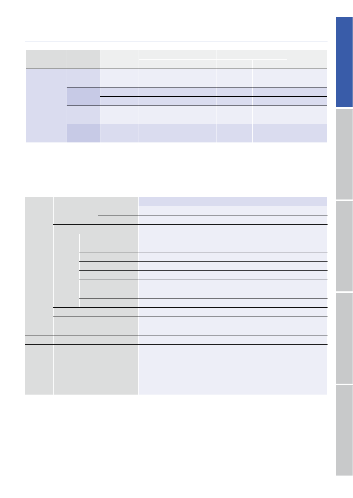
Signal name
(abbreviation)Pin number
(CN1A)Function
PMDSA1S3P01
Pulse input
(CW)1
2Inputs the drive pulse for the rotation in the CW direction.
Pulse input
(CCW)3
4Inputs the drive pulse for the rotation in the CCW direction.
Power down input
(PD)5
6
Inputting the PD signal turns off the current that flows through the stepping motor.
Photo coupler input method : Internal photo coupler ON…… PD function enabled
Rotation monitor output
(MON)MON
(collector)7
MON
(collector)8
Indicates ON when the exciting phase is at the origin position.
In the full-step, outputs once for every 6 pulses.
●The CW direction of the rotation of the stepping motor is the clockwise direction when viewing the stepping motor from the output axis side(flange side).
The CCW direction is the counterclockwise direction when viewing the stepping motor from the output axis side
(flange side)
.
DC input
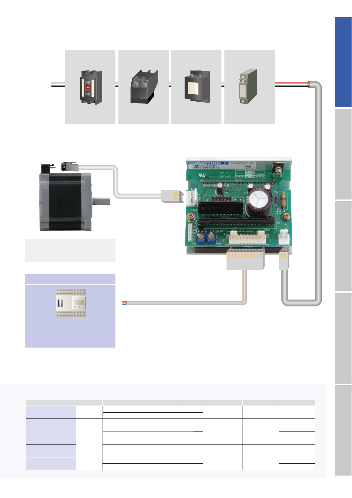
Each section name of the driver
1DC source connector
(CN2)
………Connect the DC source.
2Stepping motor output connector
(CN3)
………Connect the stepping motor drive line.
3I/O signal connector
(CN1A)
………Connect the I/O signal.
4Function selection DIP switchpack
(SL, F/R, A, B, C)
………Select the function depending on your specification.
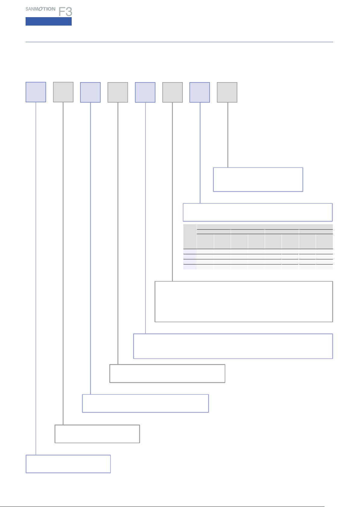
Function selection DIP switchpack
Operation, connection, and function
SL Automatic current reduction
ON 100 % of current rating when stopped
OFF
Approx. 50 % of current rating when stopped
・The factory settings are shown in the
figure above.
・Before changing the settings of the
function selection DIP switches, turn off
the source of the PM driver.
Note 1)The temperature increase in the
motor driver can be controlled
by setting SL to OFF
(approx. 50 %
of the rated current)
.
Note 2)
The output torque when SL is OFF
(approx. 50 % of the rated current)
is approx. 50 % of that when SL is
ON
(100 % of the rated current)
.
1SL
(auto current down selection)
Select the auto current down function.
2F/R selection
(Note)
This switch is not used.
Do not set it to OFF.
DIP switch Step angle Number of drive pulses per one period
of phase current
A B C
ON ON
OFF
Basic step angle 1/1
(1.2°
pulse)6
ON OFF Basic step angle 1/2
(0.6°
pulse)12
OFF ON Basic step angle 1/4
(0.3°
pulse)24
OFF OFF Basic step angle 1/8
(0.15°
pulse)48
OFF OFF ON Basic step angle 1/16
(0.075°
pulse)48
・When the DIP switch “C”=“ON”(1/16 division)
, the internal circuit
(stepping motor)
operates at the rising edge and falling edge of the drive pulse. If the duty ratio of the
drive pulse moves out of the adjustment significantly by 50 %, operation becomes
unstable.
3・4・5A, B, C
(step angle setting)
Set the step angle
System configuration
I/O signal function
3
4
1 2 3 4 5