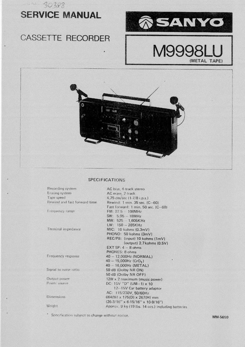
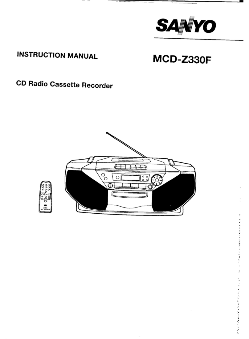
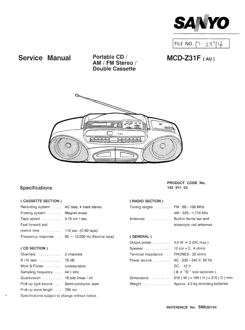
Sanyo M1990FE User manual

SERVICE
MANUAL
p~
|
qe
SANYO
MINI
AM/FM
STEREO
RADIO
CASSETTE
RECORDER
MISSOFE
EUROPE
©)
®
5
wm
>
142
36005
SPECIFICATIONS
Power
Source
Frequency
Response
[Headphonel
DC
ica
6V
(Mignonzellen,
R6
x
4)
Fe203
(Overall)
...............ccce
cee
eee
40Hz
~
8kHz
Output
Power
Metal
(Overall)
.................00.000c
ee
40Hz
~
8kHz
Sp6ak@ls
ye
cheapie
cache
ig
ti
eakwoked
toaad
ote
1,400mW
(max.)
Erase
Ratio
(Overall)
Headphone
(10%
dist.)
.............0064.
23mW
x
2
F208
.....
cece
ieee
eee
eee
eeetaeseneeeens
60dB
Current
Consumption
(at
Vol.
min.)
Signal
to
Noise
Ratio
(with
Fe2O3)
......
46dB
Record
made
(Fe203)
................665
145mA
Crosstalk
(with
Fe2O3)
Playback
mode
.....................0006-
135mA
Track
tO
Track
2.0...
eee
cece
eee
70dB
Fast
Forward/Rewind
mode............
170mA
Channel
Separation
(with
Fe2O3)
.......
38dB
Recording
System
...................0..56.
AC
Bias
Harmonic
Distortion
(with
Fe2O3)
.......
4.0%
Erasing
System
.................6.0
senses
Magnet
Erasing
Terminal
Impedance
Tape
Speed
si62c00eiscees
essed
tees
1-7/8ips.
+3%
MIGin
ds
sscevsnnititadas
ventaheeteated
coasntels
0.3mV/6kQ
Wow
&
Flutter
...............
cc
cece
cece
ee
eee
0.35%
UNWTD.
Headphone
.............ccceeee
cece
cece
eee
320
Fast
Forward/Rewind
Time
..............
200sec.
(with
C-60)
Oscillation
Frequency
....................
50kKHz
Frequency
Response
[Speaker]
Frequency
Range
Fe2O3
(Overall)
...............ccce
eee
ee
ee
125Hz
~
8kHz
BM
os
shecdomcostent.
ft
tan
atta
samasbanbaetan’
525
~
1,605kHz
Metal
(Playback)
.........................
125Hz
~
12kHz
EM
iio
dtateitaee
oN
wah
ade
eeu
88
~
108MHz
—Specifications
subject
to
change
without
notice.—
NOTE:
The
above
mentioned
specifications
are
mainly
based
on
the
IHF
measurements
standard.
They
can
therefore
not
directly
be
compared
with
specifications
based
on
the
DIN
standard
or
other
standards.
WM-
7752

DISASSEMBLY
INSTRUCTIONS
GENERAL
REMARKS
CASSETTE
COMPARTMENT
LID
REMOVAL
Before
disassembling
the
unit,
spread
a
soft
rubber
mat
or
a
1.
Open
the
cassette
compartment
lid
by
pressing
the
cloth
on
the
workbench.
(Do
not
spread
anything
which
is
STOP/EJECT
button
and
take
out
the
cassette
tape.
likely
to
cause
static
electricity.)
Do
not
make
grease
stains
and
scratches
over
the
unit.
2.
Unlock
the
clicks
of
the
lid
from
the
Cabinet
Top
by
pushing
Reassemble
the
unit
noting
the
kinds
of
screws
and
the
solder-
both
sides
of
the
lid
forcibly.
ing
and
arrangement
of
the
leads.
Refer
to
“Wiring
Diagram
and
Exploded
Views”
for
correct
assembly.
HANDLE
REMOVAL
1.
Lock
the
right
and
left
Stoppers
by
pushing
them
aginst
the
Cabinet
Bottom.
Cassette
Compartment
Lid
3.
Reassemble
in
reverse
order.
Stopper
oe
CABINET
BOTTOM
REMOVAL
1.
Before
removing
the
Cabinet
Bottom,
be
sure
to
release
the
2.
Push
down
the
Handle,
so
that
it
touches
the
unit
body.
Handle
Stoppers
from
the
Cabinet
Bottom.
2.
Turn
over
the
unit
and
open
the
battery
compartment
lid.
Then,
take
out
the
four
batteries
from
the
compartment
and
remove
the
three
screws
(1
~
3)
fastening
the
Cabinet
3.
Pull
one
side
of
the
Handie
downward
about
15mm
and
do
Bottom.
the
same
for
the
other
side.
Then,
remove
the
Handle
by
pulling
the
both
sides.
Battery
Compartment
Lid
4.
Reassemble
in
reverse
order.

3.
DISASSEMBLY
INSTRUCTIONS
(continuea)
Insert
the
flat-bladed
tip
of
the
screwdriver
into
a
slot
on
the
Cabinet
Bottom.
Pry
the
three
slots
one
by
one
to
open
the
Cabinet.
Cabinet
Bottom
Cabinet
Top
NOTE:
Be
careful
not
to
scratch
the
Cabinet
with
the
screwdriver.
Lift
the
Cabinet
Bottom
in
the
direction
of
the
arrow,
pull
out
the
Connector
of
the
Rod
Antenna
from
the
Radio
Tuner
P.C.Board,
and
then,
remove
the
Cabinet
Bottom.
Reassemble
in
reverse
order.
CABINET
TOP
REMOVAL
1.
Remove
the
Cabinet
Bottom
by
following
its
removal
in-
structions
and
disconnect
the
two
speaker
leads.
Detach
the
Tuning
Knob,
Volume
Control
Knobs,
Band
Select
Switch
Knob,
Tape
Select
Switch
Knob,
Tone
Switch
Knob,
FM
Mode
Switch
Knob,
and
the
Jack
Plate.
Remove
the
two
screws
(4
and
5)
and
detach
the
Band
Select
Lever
and
the
Band
Select
Plate.
Band
Select
Lever
Band
Select
Plate
Band
Select
Switch
.
Remove
the
Three
red
screws
(6
~
8),
lift
the
Radio
Chassis
in
the
direction
of
the
arrow,
and
then,
detach
the
Cabinet
Top,
noting
the
speaker
lead.
.
Detach
the
Function
Switch
Knob.
NOTE:
After
the
Cabinet
Top
has
been
mounted
on
the
unit,
attach
the
Function
Switch
Knob
Reassemble
in
reverse
order.

DISASSEMBLY
INSTRUCTIONS
(continued)
AMPLIFIER
P.C.BOARD
REMOVAL
1.
Remove
the
Cabinet
Top
by
following
its
removal
instruc-
tions
and
then
disconnect
the
following
leads.
*
Four
leads
(brown,
red,
violet
and
black)
of
the
Motor
Governor
P.C.Board.
*
Two
leads
(white
and
orange)
of
the
FM
Mode
Switch
P.C.Board.
2.
Remove
the
screw
(9)
fastening
the
Amplifier
P.C.Board
and
the
washer.
Then,
detach
the
Shield
Plate.
3.
Remove
the
two
screws
(10
and
11)
fastening
the
Amplifier
P.C.Board.
Then,
remove
the
Switch
Bracket
from
the
Head-
phone
Jack
P.C.Board
by
pulling
the
Amplifier
P.C.Board
to-
wards
the
microphone
jack.
4.
Detach
the
Amplifier
P.C.Board
by
lifting
it
in
the
direction
of
the
arrow,
noting
the
leads.
Spring
Washer
Shield
Plate
5.
Reassemble
in
reverse
order.
RADIO
TUNER
P.C.BOARD
REMOVAL
1.
Remove
the
Cabinet
Top
by
following
its
removal
instructions.
2.
Remove
the
two
screws
(12
and
13)
fastening
the
Volume
Control
and
then,
the
Radio
Tuner
P.C.Board
by
lifting
it
in
the
direction
of
the
arrow.
Radio
Tuner
P.C.Board
NORE:
Do
not
turn
the
Tuning
Shaft
before
the
Radio
Tuner
P.C.Board
is
reassembled.
Securely
insert
the
shaft
of
the
variable
capacitor
into
the
Drum
when
the
Radio
Tuner
P.C.Board
is
reassembled.
3.
Reassemble
in
reverse
order.
RADIO
CHASSIS
REMOVAL
1.
Remove
the
Cabinet
Top
by
following
its
removal
instructions.
2.
Remove
the
screws
(14)
fastening
the
Pointer
Rail
and
then,
the
Mechanism
Chassis
from
the
fixtures
on
the
Radio
Chassis,
noting
the
leads.
Pointer
Rail
Radio
Chassis
3.
Reassemble
in
reverse
order.

ADJUSTMENTS
GENERAL
REMARKS
e
Before
adjusting
the
mechanism
of
the
unit,
wipe
the
tape
contacting
surfaces
clean
as
well
as
the
rubber
surfaces
of
the
driving
parts
with
a
soft
cloth
soaked
in
alcohol.
Trouble
may
occur
because
of
oil
and
grease
stains.
e@
Keep
the
belts
clean
while
the
adjustments
are
performed.
EQUIPMENT
REQUIRED
@
VTVM
Frequency
Counter
Dummy
Load
(330)
DC
Constant-voltage
Regulator
Test
Tapes
*
3kHz
Test
Tape
(Example:
TEAC
MTT-111)
for
Tape
Speed
Adjustment
*
10kHz
Test
Tape
(Example:
TEAC
MTT-114)
for
Head
Azimuth
Adjustment
*
1kHz
Test
Tape
(Example:
TEAC
MTT-118)
for
Playback
Balance
Adjustment
Normal
tape
for
Recording
and
Playback
operations
(Example:
TDK
AC-222)
e
Alignment
Tool
Before
the
Electrical
Adjustment,
set
the
unit
as
follows:
*
Function
Switch
........0000...c
cc
cccecceeeeeeeeeeaeeeenanas
TAPE
*
Tape
Select
Switch
.................c0ccccc
eee
sees
eee
NORMAL
*
Tone
SWitCh
........00.
ccc
cece
ccc
eeee cece
ees
eenaeenunenes
HIGH
NOTE:
Supply
6.0V
DC
from
the
constant-voltage
regulator
to
the
external
power
jack
for
the
adjustment.
NOTES
ON
HANDLING
THE
CHIP
ELEMENT
Pay
due
caution
to
the
following
items:
1.
Donot
use
the
removed
chip
element
again.
2.
Usea
soldering
iron
of
less
than
30W.
*
The
soldering
iron
should
not
touch
the
body
of
the
chip
element.
Complete
soldering
in
a
short
time.
Apply
solder
to
the
chip
element
as
illustrated
below.
Chip
Element
Solder
Chip
Element
Solder
P.C.Board
(Incorrect)
(Correct)
FLYWHEEL
THRUST
ADJUSTMENT
The
clearance
between
the
Flywheel
Thrust
and
the
Flywheel
should
be
0.05
~
0.15mm
with
the
Chassis
turned
over.
lf
necessary,
adjust
the
clearance
by
the
following
procedure.
1.
While
moving
the
Capstan
up
and
down,
slowly
turn
the
Fly-
wheel
Thrust
clockwise
to
obtain
the
clearance
of
“O”
(zero)
between
the
Thrust
and
Flywheel.
NOTE:
Do
not
turn
the
Flywheel
Thrust
forcibly.
Adjustment
S|
|e
Flywheel
Support
—
Flywheel
Thrust
eee
i
i
|
0.05
~
0.15mm
/
Flywheel
——’
+
2.
Turn
the
Thrust
counter-clockwise
by
45°
~
90°
(approx.)
from
the
position.
3.
After
the
adjustment,
secure
the
Thrust
with
paint
or
glue.
POWER
SWITCH
ADJUSTMENT
1.
Check
to
see
that
the
clearance
of
the
switch
contacts
is
about
0.5mm
with
the
Power
Switch
in
contact
with
the
Switch
Actuate
Arm
as
illustrated.
Screw
=
;—
Power
Switch
\
/
/
He
~
Switch
On;
Actuate
Arm
=
“O”
(zero)
qi
V
\
\
\__gwiten
Bracket
~y
[|
0.5mm
2.
If
necessary,
loosen
the
screws
fastening
the
power
switch
and
move
the
switch
to
the
specified
position.
3.
After
the
adjustment,
tighten
the
screw
and
secure
the
switch
with
paint
or
glue.

ADJUSTMENTS
(continuea)
TORQUE
LIMITTER
ADJUSTMENT
This
adjustment
shall
be
performed
to
prevent
the
torque
limit-
ter
intrusion
of
more
than
required
into
the
Flywheel
when
the
unit
is
set
in
the
fast
forward
or
rewind
mode.
1.
Supply
6V
DC
into
the
Motor
Governor
P.C.Board
to
rotate
the
Motor.
Then,
set
the
unit
in
the
fast
forward
mode
by
pressing
the
F.FWD
button.
2.
Loosen
the
screw
by
turning
it
about
90°
counter-clockwise
from
the
position
where
the
screw
is
securely
tightened
as
illustrated.
Torque
Limitter
Flywheel
3.
Slowly
turn
the
adjusting
screw
counter-clockwise
until
the
rotation
of
the
Torque
Limitter
stops
while
the
Flywheel
Support
is
held
in
place.
4.
Turn
the
adjusting
screw
180°
~
200°
clockwise
from
the
above
position
and
confirm
that
the
clearance
of
0.2
~
0.3mm
is
obtained
between
the
shaft
of
the
Torque
Limitter
and
the
Idler
Adjust
Plate
as
illustrated.
Torque
Limitter
Shaft
0.2
~
0.3mm
Idler
Adjust
Plate
Turn
to
adjust.
5.
After
the
adjustment,
tighten
the
fastening
screw
and
secure
the
fastening
screw
and
adjusting
screw
with
paint
or
glue.
TAPE
SPEED
ADJUSTMENT
1.
Connect
the
frequency
counter
to
the
headphone
jack
as
il-
lustrated
and
remove
the
battery
compartment
lid.
Frequency
Counter
3,000Hz
(+
3%)
HEADPHONES
2.
Insert
a
3kHz
test
tape
(Example:
TEAC
MTT-111)
into
the
the
cassette
compartment
and
play
back
the
test
tape.
3.
While
playing
back
the
test
tape,
adjust
the
tape
speed
by
turning
the
potentiometer
(P801)
on the
Motor
Governor
P.C.Board
until
the
frequecy
counter
reads
3,000Hz
(+
3%).
Tape
Speed
Adjusting
Volume
HEAD
AZIMUTH
ADJUSTMENT
1.
Connect
the
two
VTVMs
and
the
dualtrace
synchroscope
to
the
headphone
jack
as
illustrated.
Then,
set
the
dualtrace
synchroscope
as
follows:
*
IMODE
onscsn
geal
bagcd
Tass
wea
ats
CHOP
(chopped)
*
SOURCE
.............
cece
INT
(internal),
CH1
or
CH2
”
AUTO
(automatic)
STEREO
HEADPHONES

ADJUSTMENTS
(continued)
NOTE:
Adjust
the
field
on
the
synchroscope
with
the
VOLT.
ADJ.
and
TIME
ADJ.
2.
Insert
the
10kHz
test
tape
(Example:
TEAC
MTT-114)
into
the
cassette
compartment.
While
playing
back
the
test
tape,
turn
the
azimuth
adjusting
screw
until
the
wave
forms
of
the
right
and
left
channels
are
superimposed
and
set
to
optimum
at
the
maximum
reading
on
the
VTVM.
Adjustment
S|
Azimuth
Adjusting
Screw
R/P
Head
3.
After
the
adjustment,
secure
the
adjusting
screw
with
paint
or
glue.
PLAYBACK
BALANCE
ADJUSTMENT
1.
Connect
the
two
VTVMs
to
the
headphone
jack
as
illustrat-
ed
and
insert
a
1kHz
test
tape
(Example:
TEAC
MTT-118)
into
the
cassette
compartment.
VTVM
VTVM
Dummy
Load
332
STEREO
HEADPHONES
Dummy
Load
330
2.
While
playing
back
the
test
tape,
check
that
the
left
channel
output
is
identical
to
the
right
channel
output
on
the
VTVMs.
If
necessary,
turn
the
potentiometer
(P202)
until
the
right
channel
output
becomes
equivalent
to
the
left
channel
output.
RECORDING
BIAS
ADJUSTMENT
LEFT
CHANNEL
1.
Connect
the
audio
signal
generator
and
the
attenuator
to
the
left
channel
microphone
jack,
and
the
VTVM
to
the
left
channel
output
terminal
of
the
headphone
jack
as
illustrated.
Attenuator
0.031
mV
(-90dB)
Audio
Signal
Generator
1kHz,
8kHz
STEREO
HEADPHONES
7
|
Dummy
Load
330
1kHz
=
8kHz,+3dB
2.
Insert
a
normal
tape
(Example:
TDK
AC-222)
into
the
cassette
compartment
and
alternately
record
the
1kHz
and
8kHz
signals
from
the
audio
signal
generator
at
0.031mV
(-90dB)
on
the
tape
several
times.
3.
While
playing
back
the
recorded
signals,
check
that
the
8kHz
signal
output
is
identical
to
the
1kHz
signal
output
or
the
deviation
is
+
3dB
on
the
VTVM.
4.
If
necessary,
adjust
the
output
by
turning
the
potentiometer
(P101)
and
re-check
the
output
of
each
signal
by
playing
back
the
signals
after
recording
operation
of
the
signals.
5.
Repeat
the
above
adjustment
until
the
specified
output
is
obtained.
RIGHT
CHANNEL
Connect
the
audio
signal
generator
and
the
attenuator
to
the
right
channel
microphone
jack,
and
the
VTVM
to
the
right
channel
terminal
of
the
headphone
jack.
Then,
adjust
the
potentiometer
(P201)
for
the
right
channel
by
following
the
same
procedure
as
in
LEFT
CHANNEL.
=7=

EQUIPMENT
REQUIRED
Generator
Scope
Loop
Antenna
VTVM
Distortion
Meter
NOTE:
Use
an
alignment
tool
with
plastic
grip
for
all
adjustments.
AM
ALIGNMENT
Alignment
AM
Standard
Signal
Generator
FM
Standard
Signal
Generator
Stereo
Signal
Generator
Frequency
Counter
TUNER
ADJUSTMENT
Dummy
Antenna
(750,
unbalanced
type)
for
FM
e
Oscilloscope
e@
Dummy
Load
(339)
e
Alignment
Tool
e@
Before
performing
the
adjustment,
set
the
unit
as
follows:
*
Function
Switch
......0.0.0..
0
cece
ccecccecceccceececues
RADIO
“
FM
Mode
Switch
........000..0
cece
cccccecceeccccuseues
MONO
*
Tone
SWitch
«2.0.0.0...
ccc
ec
ccec
ec
ceceescccuueueeees
HIGH
*
Volume
Control
.........0..
0
cece
cece
cc
ceccceesceeeecues
Center
Standard
Test
Frequency
400Hz
and
Modulation
30%
at
AM
Connections
Calibration
of IF
INPUT
Connect
standard
loop
antenna
to
output
terminal
of
gene-scope.
Place
loop
antenna
60cm
away
from
bar
antenna.
—_|_.
OUTPUT
Connect
input
terminal
of
gene-
scope
to
detector
output
terminals.
(TP9
or
TP11,
and
TP10)
Frequency
of
Signal
Generator
Tuning
Dial
Setting
Remarks
Adjustments
Obtain
symmetrical
curve
and
maximum
amplitude.
455kHz
Low
End
Calibration
of
Tuning
Range
Adjustment
of
Tracking
Connect
standard
loop
antenna
to
output
of
signal
generator.
Place
loop
antenna
60cm
away
from
bar
antenna.
i
ea
Connect
VTVM
with
330
dummy
load
and
oscilloscope
to
Ext.
Speaker
terminal.
510kHz
Obtain
sine-wave
of
400Hz
and
maximum
amplitude.
1,670kHz
High
End
TC4
(PVC)
600kHz
L3
(bar
ant.
coil)
Max.
1,400kHz
|
1,400kHz
TC3
(PVC)
1
Connections
Alignment
Calibration
of
IF
INPUT
Place
output
of
gene-scope
on
Trap
Coil
(T1).
OUTPUT
Connect
input
terminal
of
gene-
scope
to
detector
output
terminals.
(TP9
or
TP11,
and
TP10)
Standard
test
frequency
400Hz
and
deviation
22.5kHz
Frequency
of
Signal
Generator
Tuning
Dial
Setting
Remarks
Adjustments
Obtain
symmetrical
curve
and
maximum
amplitude.
Turn
T3(blue
core)
fully
counter-
clockwise
T2.
10.7MHz
Low
End
Obtain
S
curve
and
maximum
amplitude.
T3
(blue
core)
Calibration
of
Tuning
Range
Adjustment
of
Tracking
Connect
signal
generator
to
antenna
terminals
(TP1
and
TP2)
through
dummy
antenna
(750,
unbalanced
type).
Connect
VTVM
with
33.0
dummy
load
and
oscilloscope
to
Ext.
Speaker
terminal.
87.2MHz
L2
Obtain
sine-curve
and
maximum
amplitude.
109.0MHz
|
HighEnd
TC2
(PVC)
90MHz
Max.
|
4
90MHz
{
u4
|
106MHz
106MHz
TC1
(PVC)
Repeat
the
above
adjustment.

TUNER
ADJUSTMENT
(continuea)
Before
performing
the
adjustment,
set
the
unit
as
follows:
3.
Adjust
the
input
measuring
instruments
as
follows:
e@
Function
Select
Switch
...................:::e
cece
eee
eee
ee
RADIO
e
Stereo
Signal
Generator
e@
Band
Select
Switch
...............00..
cece
cece
cence
eee
ee
ees
FM
*
Pilot
Signal
..............
7.5kHz
dev.
(modulation
10%)
@
FM
Mode
Switch
.............0.....
2.
ccc
eee
eee
ee
ees
STEREO
*
Stereo
Signal
.............
67.5kHz
dev.
for
main
signal
@
Tone
Switch
2.00.0...
e
cece
acces
ee
eenenenenes
HIGH
(modulation
90%)
@
Volume
Control
.......0..0..
2c
ccc
ccc
cece
cece
ence
eeeeeeeeee
Center
*
Modulation
Frequency
....................
cece
eu
ee
400Hz
e
FM
Standard
Signal
Generator
tone
(V.C.0.)
ADJUSTMENT
*
Signal
Generator
Frequency
.................0.-
98MHz
Connect
the
Frequency
counter
to
the
twelfth
pin
in
IC2
*
Signal
Generator
Output
...............0......045
66dBu
(LA3361).
4.
Set
the
tuning
frequency
to
98MHz.
2.
Adjust
the
potentiometer
(P1)
until
the
oscillation
frequency
of
IC2
becomes
19kHz
(+
20Hz).
5.
Adjust
the
potentiometer
(P2)
by
following
the
Chart
below.
CHANNEL
SEPARATION
ADJUSTMENT
1.
Connect
the
stereo
signal
generator
and
the
FM
standard
signal
generator
through
the
759
dummy
antenna
(unbal-
anced
type)
to
the
antenna
terminals
(TP1
and
TP2)
on
the
Radio
Tuner
P.C.Board
.
NOTE:
Use
an
alignment
tool
with
plastic
grip
for
all
adjustments.
2.
Connect
the
VTVM
with
339
dummy
load
distortion
meter,
and
oscilloscope
to
the
left
channel
terminal
of
the
head-
phone
jack.
Connections
Tuning
Dial
Setting
Remarks
Alignment
Adjustment
OUTPUT
Pilot
(19kHz)
and
Sub
channel
signals
of
Stereo
SG
Maximize
amplitude
of
Oscillo-
scope
and
VTVM
reading
with
FM
Stereo
minimum
distortion.
Signal
Separation
—ON
Connect
measuring
instru-
ments
to
L
channel
R
channel
and
Pilot
Ext.
Speaker
terminal
signal
of
Stereo
SG
Minimize
amplitude
of
Oscillo-
scope
and
VTVM
reading.
—ON
Repeat
the
above
adjustments.
6.
Connect
the
measuring
instruments
to
the
right
channel
terminal
of
the
headphone
jack
and
perform
the
adjustment
by
following
the
Chart
below.
Connections
Tuning
Dial
Setting
Alignment
Adjustment
Remarks
OUTPUT
Pilot
(19kHz)
and
Sub
channel
signals
of
Stereo
SG
Maximize
amplitude
of
Oscillo-
scope
and
VTVM
reading
with
FM
Stereo
—ON
minimum
distortion.
Signal
Separation
Connect
measuring
instru-
ments
to
R
channel
Ext.
Speaker
terminal
L
channel
and
Pilot
signal
of
Stereo
SG
Minimize
amplitude
of
Oscillo-
scope
and
VTVM
reading.
—ON
Repeat
the
above
adjustments.
7.
Repeatedly
perform
the
adjustments
in
Items
5
and
6
to
minimize
the
signal
leakage
for
both
right
and
left
channels.
Then,
reduce
the
difference
between
each
channel
separa-
tion
by
adjusting
the
potentiometer
(P2).
—9—

DIAL
CORD
STRINGING
Mount
the
Drum
on
the
Radio
Chassis
as
illustrated.
Tie
the
dial
cord
of
length
800mm
(effective
length:
770mm)
and
diameter
$0.3
to
the
spring
and
hook
the
spring
to
the
illustrated
position
of
the
drum.
Engage
the
dial
cord
as
illustrated
in
the
following
order.
Drum
—
Pulley
A
—
Pulley
B
—
Tuning
Shaft
(4
turns)
—
Pulley
C
—
Pulley
D
—
Pulley
E
—
Pulley
F
—
Drum
—
Spring
Hook
the
dial
cord
to
the
spring
and
tie
the
cord
where
the
spring
tip
extends
to
the
scratch
mark
as
illustrated.
Pointer
Start
Position
¥
Gaccanae
Rail
PulleyD
Expand
the
spring
to
this
scratch
mark.
5.
Secure
the
place
where
the
spring
is
hooked
to
the
drum
and
the
knot
in
the
dial
cord
with
paint
or
glue.
Turn
the
shaft
of
the
variable
capacitor
counter-clockwise
until
it
stops.
Then,
fit
the
shaft
to
the
drum
and
mount
the
Radio
Tuner
P.C.Board
on
the
Radio
Chassis.
Attach
the
pointer
to
the
dial
cord
and
fit
the
pointer
to
the
starting
position
mark
on
the
pointer
rail
as
illustrated.
Turn
the
tuning
shaft
idly
counter-clockwise
and
confirm
that
the
pointer
is
correctly
positioned.
—»p
Starting
Position
>"
PulleyB
Tuning
Shaft

Ref.
No.
CAI
CA2
CA3
CA4
CAS
CA6
CA7
CA8
CAQ
CA10
CA1i
CA12
CA13
CA14
CA15
CA16
CAI7
CA18
CA19
CA20
CA21
CA22
CA23
CA24
CA25
CA26
CA27
CA28
CA29
CA30
CA31
CA32
CA33
CA34
Cx1
CX2
CX3
CX4
CX5
CX6
CX7
Parts
No.
PACKAGE
141
141
141
144
141
141
ACCESSORIES
144
141
6
1419
60203
6
1449
78300
6
1449
78400
6
4559
00100
6
2519
14190
6
2519
13090
4
1529
70261
4
1919
71570
4
2419
71002
0
1769
00700
2
1819
13302
142
6
4119
31522
CABINET
144
144
141
144
141
141
144
144
144
141
144
141
144
141
144
144
141
141
141
141
144
141
141
141
141
144
141
141
14
141
144
141
4
2359
70990
0
1249
20401
2
2449
41500
2
1649
14700
2
1519
29002
2
1559
05600
2
1639
40400
2
1559
04500
2
2449
35800
2
4469
35400
0
1119
81101
2
2449
37900
2
1649
16100
2
1649
16000
2
1649
16300
2
1649
16400
2
1649
15900
0
5519
08400
2
1649
16500
2
2719
16901
2
3679
30601
2
7319
48400
2
8559
00400
2
4219
12100
0
8539
01204
0
1719
09004
0
8539
01104
4
1519
70981
2
4469
37800
2
4469
37700
2
4469
29800
2
1339
24404
0
1119
81204
4
2449
70201
2
3849
03900
103
3
1302
60811
103
3
1302
62019
101
3
1202
60814
103
3
1202
61014
103
3
1302
00611
101
3
1302
60611
110
3
3202
60082
PARTS
LIST
Description
Indvidual
Carton
Styrofoam
Case,
Left
Styrofoam
Case,
Right
Serial
No.
Sheet
Poly
Cover
Poly
Cover
Headphone
AC
Adaptor,
6CV220E
Cassette
Shoulder
Belt
Assy
Carrying
Case
Instruction
Manual
RT
Pin
Socket
Cassette
Lid
Assy
Cushion,
Cassette
Lid
Knob,
Function
Speaker
Grille
Speaker
Ring
Tuning
Knob
Ring,
Mike
Net,
Mike
Cushion,
Mike
Cabinet
Top
Assy
Sheet,
Volume
Volume
Knob,
Right
Volume
Knob,
Left
Tone
Knob
Tape
Select
Knob
Band
Select
Knob
Eject
Gear
Assy
Switch
Knob
Handle
Holder
Jack
Plate
Cam
Spring,
Cam
Screw
w/Washer
Handle
Spring
R
Assy
Handle
Assy
Handle
Spring
L
Assy
Speaker
(3.20)
[SP1]
Cushion
Cushion
Cushion
Battery
Lid
Cabinet
Bottom
Assy
Rod
Antenna
Bracket,
Antenna
Screw,
Pan
Hd.
Tapping-2
Screw,
Pan
Hd.
Tapping-2
Screw,
Flat
Hd.
Screw,
Flat
Hd.
Tapping-2
Screw,
Pan
Hd.
Tapping-2
Screw,
Pan
Hd.
Ext.
Star
Washer
+M2.6x8
+M2.6x20
+M2.6x8
+M2.6x10
+M2.0x6
+M2.6x6
M2.6
Qt
—-
oo
a
en
Cree Cree
Carer
eee
]H]=
=
9
$M
OH
BH
SB
woe
opm
Se
Se es
oe
oe
eos
sis
y
Ret.
Parts
No.
Description
Q’ty
RADIO
CHASSIS
DCt
141
0
5289
01000
Pointer
Rail
Assy
1
DC2
141
2
5119
06300
‘Pointer
1
DC3
141
2
8539
45500
—
Spring,
Earth
1
DC4
4
2229
73500
Volume
Control
(A-20kQ
/Right)
[VR2]
1
DC5
141
2
2419
24604
Veil,
VOLUME
2
DC6
141
2
7529
90700
Pin
1
DC7
141
2
8259
07800
—_—Roller
1
DC8
4
1539
70660
Microphone
[BM1]
|
Dcg
141
2
7519
53400
—‘
Tuning
Shaft
1
DC10
=141
0
3119
20501
Radio
Chassis
Assy
1
DC11
141
2
4219
21800
Screw
{
DC12
=
141
2
5389
03100
Drum
1
DC13.
141
2
8519
70200
Spring,
Slide
Base
1
DC14
=
141
2
7319
50600
_Band
Select
Plate
1
DC15
141
2
7319
50700
—_
Band
Select
Plate
1
DC16
=.
141
2
4219
12100
Screw
w/Washer
1
DC17
=:
144
2
6219
03300
_—_—
Band
Select
Lever
1
0C18
141
2
4219
06300 Screw
1
DCi9
§=141
2
3769
11600
Spacer,
PVC
1
DC20
141
2
7539
07500
—_—
Post,
Volume
2
DC21
141
2
4469
11901
Damper
2
DC22
141
2
3229
32301
Shield
Plate
1
DC23
141
2
4469
17900
Cushion,
Cassette
1
DC24
141
2
3529
08600
Spacer,
Record
Lock
1
DC25
141
2
7439
25000
—_Lever,
Function
1
DC26
141
2
4219
08900
Screw
3
DC27
141
2
3659
17400
_
Bracket,
Function
1
DC28
4
2029
71780
LED
Indicator
P.C.B.
Assy
(See
PCB4)
1
DC29
4
2319
75170
Switch
P.C.B.
Assy
(See
PCBS5)
1
DC30
4
1259
71611
Radio
Tuner
P.C.B.
Assy
(See
PCB1)
1
DC31
4
1329
77450
Amplifier
P.C.B.
Assy
(See
PCB2)
1
0C32
4
2359
75490
Headphone
Jack
P.C.B.
Assy
(See
PCB7)
1
DC33
4
2359
75481
—
Ext.
Power
Jack
P.C.B.
Assy
(See
PCB8)
1
DY1 102
3
1302
00511
Screw,
Pan
Hd.
Tapping-1
+M2.0x5
2
DY2
101
3
1302
00411
=
Screw,
Pan
Hd.
+M2.0x4
2
DY3
624
3
0908
00000
String,
60.4
1
DY4
101
3
1702
00511
=
Screw,
Bind
Hd.
+M2.0x5
2
DY5
112
3
1302
00040
ERing
M2.0
1
DY6
101
3
2501
70413
Screw,
Cyllinder
Hd.
-M1.7x4
1
DY7
101
3
1302
00423
Screw,
Pan
Hd.
+M2.0x4
2
DY8
103
3
1302
00811
Screw,
Pan
Hd.
Tapping-2
+M2.0x8
1
DY9
110
3
1102
00023
Sm.
Round
Washer
M2.0
1
DY10
=
=128
3
1317
06013
PI
Screw-3,
Pan
Hd.
+M1.7x1.6
2
DY11
110
3
2101
70013
Spring
Washer-2
M1.7
1
DYi2
101
3
1302
60611
Screw,
Pan
Hd.
+M2.6x6
1
DY13.
101
3
1202
60411
Screw,
Flat
Hd.
+M2.6x4
2
NOTES:
1.
Parts
order
must
contain
Model
Number,
Part
Number
and
Description.
2.
Ordering
quantity
of
screws
and
resistors
must
be
multiple
of
10
pes.

CABINET
EXPLODED
VIEW

RADIO
CHASSIS
EXPLODED
VIEW
(continuea)
bvl2——©
b¢24—_-®
pc2s
ory

MECHANISM
PARTS
LIST
net
Parts
No.
Description
Q’ty
fet:
Parts
No.
Description
Q’ty
MECHANISM
MC64
141
2
7319
47500
Shut
Off
Rack
Lever
1
MC1
141
0
3119
19701
Chassis
Assy
1
MC65
141
2
3529
30600
Spacer,
Rack
Lever
1
MC2
=
141-0
7419
32100
Completed
Pause
Lever
1
MC66
141
2
3529
30700
Spacer,
Rack
Lever
1
MC3
141
2
8519
93800
Spring,
Slide
Base
1
MC67
141
2
4219
24900
Screw,
Flat
Hd.
+M1.4x4.0
2
MC4
=:
141-0
7419
32200
Completed
Slide
Base
1
MC68
141
0
5519
08200
Shut
Off
Gear
Assy
1
MC5
=:
141.
2
8219
29800
_—‘
Tape
Guide
1
MC69
141
2
7319
47400
Shut
Off
Link
Lever
1
MC6
=:
141.
2
8529
04600
Spring,
Erase
Head
1
MC70
141
2
7439
23900
Rack
Lever
ACT Arm
1
MC7
=.
141:
0
7439
10300
Erase
Head
Arm
Assy
1
MC71
141
2
8549
07700
Spring,
Shut
Off
Link
1
MC8
=
147
2
8539
38500
=
Spring,
Head
1
MC72
141
0
5319
05800
Friction
Assy
1
MC9
=
141.
2
3529
18102
Spacer,
Head
1
MC73
141
2
4419
15400
Felt,
Friction
Sensor
|
MC10
4
2429
72010
R/P
Head
1
MC74
141
2
7439
24900
Sensor
ACT
Plate
1
MC11
141
2
4729
07700
~—_
Lug
1
MC75
141
2
8559
01500
—
Spring,
Friction
Sens
1
MC12
141
2
4219
03000
Screw
+M2.0x3.0
1
MC76
141
2
6619
03300
Counter
Pulley
1
MC13
141
2
4179
02200
—_—Nut,
Head
1
MC77
141
2
8549
05400
—
Spring,
Shut
Sensor
1
MC14
141
2
8529
06300
—
Spring,
Pinch
Roller
1
MC78
141
2
3529
30400
Spacer,
Sensor
Plate
1
MC15
141
0
5419
03400
Pinch
Roller
Assy
1
MC79
141
2
7319
48300
Shut
Off
Sensor
1
MC16
141
2
1219
18101
Chassis
Panel
1
MC80
141
2
3529
30200
Spacer,
Slide
Lever
3
MC17
141
2
4219
24800
Screw,
Pan
Hd.
+M1.7x2.0
7
MC81
141
2
7319
47300
Slide
Plate
1
MC18
141
2
3529
26900
Spacer
1
MC82
141
2
4539
26200
Washer
2
MC19
141
2
7439
24200
—‘
Take-up
Actuator
1
MC83
141
2
5519
40200
Idler
Pulley
1
MC20
141
0
3169
06800
Eject
Bracket
Assy
{
MC84
141
2
4539
23900
Washer
2
MC21
141
2
3529
30000
Spacer,
Pause
Lever
1
MC85
141
2
5519
40300
Idler
Gear
1
MC22
141
2
4219
24300
Screw
+M1.4x2.0
5
MC86
141
2
7439
24000
Pause
Arm
1
MC23
141
2
2419
25500
Beil,
Switch
1
MC87
141
0
3519
19700
Shut
Off
Plate
Assy
1
MC24
141
2
3679
30500
Switch
Bracket
1
MC88
141
2
3529
27300
Spacer,
Support
Plate
1
MC25
141
2
8549
08000
Spring,
Eject
ACT
1
MC89
141
0
7419
32300
Completed
Stop
Lever
1
MC26
141
0
7319
22700
Eject
ACT
Arm
Assy
1
MC90
141
0
7419
32400
Rewind
Lever
Assy
1
MC27
141
2
7319
47800
Lever,
Shut
Off
ACT
|
MC91
141
0
7419
32500
FF
Lever
Assy
1
MC28
141
2
7319
47600
Lever,
Stop/Eject
ACT
1
MC92
141
0
8419
04500
_
Record
Lever
Assy
1
MC29_
141
2
8549
12200
Spring,
Lever
1
MC93
141
2
3519
56000
Chassis
Bracket
1
MC30
141
2
3529
29900
Spacer,
Lever
2
MC94_
141
2
8549
08100
Spring,
Rewind
Lever
2
MC31
141
2
4539
09400
Washer
2
MC95
141
2
8519
94300
Spring,
Lock
Plate
1
MC32
141
0
5219
07800
_
Flywheel
Assy
1
MC96_
141
0
3519
19800
Support
Plate
Assy
1
MC33
141
2
5649
17700
Drive
Belt
1
MC97
141
0
7319
22900
_
Base
Lock
Plate
Assy
1
MC34
141
2
5649
17400
—Take-up
Belt
1
MC98
141
2
8549
05500
Spring,
Stop
Lever
1
MC35
141
2
3519
54700
—_‘
Flywheel
Support
1
MC99
141
2
4729
01901
—_Lug
1
MC36
141
2
4469
28700
Flywheel
Thrust
1
MC100
141
2
3529
30100
Spacer,
Record
Lever
1
MC37
141
2
4729
01902
Lug
1
MC101
141
2
3529
30500
Spacer,
Record
Support
1
MC38
141
2
8559
01400
—
Spring,
Idler
Adjust
1
MC102
141
2
8549
05100
Spring,
Base
1
MC39_
141
2
3519
56600
‘Plate,
Idler
Adjust
1
MC103
141
2
3659
17600
Switch
Bracket
1
MC40_
141
0
3789
01401
—
Motor
Bracket
Assy
1
MC104
4
2319
74570
Leaf
Switch
(Power)
[$4]
1
MC41
141
2
5649
17600
Counter
Belt
1
MC105
141
2
8429
05900
Record
Lock
Plate
1
MC42
141
2
8119
09300
Counter
1
MC106
141
2
7319
47700
ACT
Lever
Plate
1
MC43
141
2
4459
15900
Cushion,
Motor
2
MC107
141
2
8429
06000
Record
Interlock
Plate
1
MC44
141
2
4219
11400
Screw
2
MC108
141
2
4569
05700
Washer
2
MC45
141
2
2449
38800
Beil,
Switch
1
MC109
141
2
8549
07600
—
Spring,
Record
Lock
1
MC46
141
2
1649
14900
Knob,
Switch
1
MC110
141
2
8549
09400
Spring,
Record
Interlock
1
MC47
141
0
7439
10200
Intercept
Arm
Assy
1
MC111
141
2
7439
27300
Switch
ACT
Arm
1
MC48
141
0
7439
10000
Shut
off
Arm
Assy
1
MC112
141
0
3169
06900
Reel
Plate
Assy
1
MC49
141
2
4539
17500
Washer
12
MC113
141
2
5519
40600
Planetary
Gear
1
MC5O
141
0
5559
06200
idler
Base
Assy
1
MC114
141
2
3529
30300
Spacer,
Planet
Gear
1
MCS1
141
2
8519
93200
Spring,
Idler
Base
1
MC115
141
2
4539
08000
Washer
3
MC52
141
2
3529
26800
Spacer
1
MC116
141
2
7439
23800
Shut
Off
Link
Arm
1
MC53
141
2
4539
18100
Washer
5
MC117
141
2
5519
40900
—_—
Rewind
Gear
1
MC54
141
2
5519
40100
—‘
Take-up
Idler
1
MC118
141
2
8559
01700
—
Spring,
Back
Tension
1
MC55_
141
2
4539
09200
Washer
j
MC119
141
2
4539
14900
Washer
1
MCS6
141
2
5519
41000
Take-up
Pulley
1
MC120
141
2
5519
36100
Gear
1
MC57
141
2
5649
17500
Shut
Off
Belt
1
MC121
141
2
7439
20800
Gear
Select
Arm
1
MCS8
141
2
4539
01800
Washer
1
MC122
141
0
7439
08800
Select
Arm
Assy
1
MC59
141
0
5519
08300
Torque
Limitter
Assy
1
MC123
141
2
3529
27000
Spacer,
Select
Arm
1
MC60
141
0
5559
06300
Idler
Arm
Assy
1
MC124
141
2
8549
05200
Spring,
Select
Cam
1
MC61
141
2
5519
36000
Wind
Gear
1
MC125
141
0
7439
08700
—
Select
Link
Assy
1
MC62
141
2
8549
07900
Spring,
Switch
Lever
2
MC126
141
2
8549
08500
Spring,
Pause
Arm
1
MC63
141
2
8549
05300
Spring,
Shut
Off
Rack
1
MC127
141
2
7439
24800
Pause
Lock
Plate
1

Ref.
MECHANISM
PARTS
LIST
(continued)
No.
Parts
No.
Description
Q’ty
MC128
141
2
8529
04500
Spring,
Pause
1
MC129
141
2
5519
40800
Supply
Gear
1
MC130
141
0
7439
10100
Review
Link
Assy
1
MC131
141
2
7319
48100
Switch
Lever
1
MC132
141
2
8549
07800
Spring,
Pause
Lever
1
MC133
141
2
7439
21300
Interlock
1
MC134
141
2
3529
29800
Spacer,
Interlock
1
MC135
141
2
8529
04400
=
Spring,
Interlock
1
MC136
141
2
4219
23500
Screw
+M1.7x4.0
1
MC137
141
0
8429
01400
Record
Plate
Assy
1
MC138
141
2
8549
05000
Spring,
Record
Plate
1
MC139
141
2
4539
09401
Washer
2
MC140
141
0
5349
01600
Reel
Spindle
Assy
1
MC141
141
0
5349
01500
Reel
Spindle
Assy
1
MC142
4
2319
75160
FM
Mode
Switch
P.C.B.
Assy
(See
PCB6)
1
MC143
4
5279
70906
Motor
Assy
(See
PCB3)
1
MZ1
127
3.1317
01613
PI
Screw-1,
Pan
Hd.
+M1.7x1.6
1
MZ2
112
3
1301
20082
ERing
M1.2
8
MZ3
112
3
1301
50082
ERing
Mi.5
11
MZ4
=
127
3.
1214
01418
—
PI
Screw-1,
Flat
Hd.
+M1.4x1.4
7
MZ5
=
127
3:
1317
02513
PI
Screw-1,
Pan
Hd.
+M1.7x2.5
3
MZ6
=
110
3
1101
70081
Sm.
Round
Washer
M1.7
2
MZ7
=.
128
3:
1317
05018
—
PI
Screw-3,
Pan
Hd.
+M1.7x5.0
1
MZ8
=
128
3:
1317
03013
PI
Screw-3,
Pan
Hd.
+M1.7x3.0
2
MZ9
ss:
128
3:
1317
02513
PI
Screw-3,
Pan
Hd.
+M1.7x2.5
1
MZ10
101
3
1302
00311
Screw,
Pan
Hd.
+M2.0x3
1
MZ11
127
3
1317
03013
PI
Screw-1,
Pan
Hd.
+M1.7x3.0
3
MZ12.
127
3.1314
03013
PI
Screw-1,
Pan
Hd.
+M1.4x3.0
4
MZ13
427
3
1314
02513
—
PI
Screw-1,
Pan
Hd.
+M1.4x2.5
5
MZ14
127
3.1214
03013
Pl
Screw-1,
Flat
Hd.
+M1.4x3.0
4
MZ15
128
3
1314
03018
—
PI
Screw-3,
Pan
Hd.
+M1.4x3.0
2
MZ16
127
3
1314
03513
PI
Screw-1,
Pan
Hd.
+M1.4x3.5
1
MZ17
101
3
1302
60411
Screw,
Pan
Hd.
+M2.6x4
1
MZ18
127
3
1314
01613
PI
Screw-1,
Pan
Hd.
+M1.4x1.6
3
MZ19
110
3.1102
00013
Sm.
Round
Washer
M2.0
2
NOTES:
1.
Parts
order
must
contain
Model
Number,
Part
Number
and
Description.
2.
Ordering
quantity
of
screws
and
resistors
must
be
multiple
of
10
pcs.

MECHANISM
EXPLODED
VIEW
Ccontinuea)
Mz2———«
Mc7
me
Mc13
Mc
——s_,
of
=
ey
e—MCI2
ZI
—@
MCI1
MC5

MECHANISM
EXPLODED
VIEW
Ccontinuea)
MZ2
gy
MC29
M028

MECHANISM
EXPLODED
VIEW
Ccontinuea)
Mc49
—-@
me111
eZ
Ree,
wz3—e
|
——MC110
|
o—mne09
|
Wes
be
Oamedt
|
3
mc107
wic106
Mzi2
o-—M6
,
i.
Mici00
=
»
weno
yy
MZ13
snP—
MC102
mci
MZ15—-,
is
oe

MECHANISM
EXPLODED
VIEW
(continued)
MC50
MC57
@—
MZ
S—mes2
eek
—
es
MC3I
Mcé2
mc4g——
Mc60
MC53
MC59
+
|
mc49—®
ness)
—19—
MECHANISM
EXPLODED
VIEW
Ccontinuea)
&——Mc49
Mz19
se
mci27
©——MZ6
+
mci2eB—=”
wuz
MZ3
——es
MC116
—Qsy
mth
©
Mc120
MZ14—@
me114—e
MC113
Mc2
)
e——MZ11
®——
M0123
gr
Mele
~20-—
ber
_
MC132
MC62
io
Lee
Mizz
a
Mc131
@——Mc136
~E
eras
Mc134
Mc133

P.C.BOARD
PARTS
LIST
be
Parts
No.
Description
Q’ty
RADIO
TUNER
P.C.B.
ASSY
PCBI1
4
1259
71611
—
Radio
Tuner
P.C.B.
Assy
1
141
2
3229
35600
—
Shield
Plate,
Tuner
1
141
2
3229
35700
Shield
Plate,
IC
1
141
2
4219
10600
Screw
2
141
2
4729
05000
Staple,
5mm
6
4
2369
70740
RTPin
11
PVC1
4
2249
70540
‘Variable
Condenser
1
$5
4
2319
74411
—
Slide
Switch
(Band
Select)
1
VR1
4
2229
73500
Volume
Control
(A-20k
©
/Left)
1
PA
4
2229
73036
—
Potentiometer
(B-10kQ)
1
BPF1
4
2539
71021
Band
Pass
Filter
1
L001
4
2599
70601
RF
Coil
1
L002
4
2589
71611
OSC
Coil
FM
1
L3
4
2579
70971
Bar
Antenna
1
1
4
2569
71283
IFT
1
T2
4
2569
70854
IFT
1
13
4
2569
71340
IFT
FM
1
14
4
2569
71350
IFTAM
1
15
4
2589
70514
OSC
Trans
1
T6
4
2569
71360
Trap
19kHz
1
17
4
2569
71360
Trap
19kHz
1
Cr
4
2539
70881
Ceramic
Filter
1
CF2
4
2539
70681
Mechanical
Filter
1
D1
4
2029
71440
Diode,
1SS95
1
D2
4
2029
71440
Diode,
1$S95
1
D3
4
2029
70790
Diode,
1TT410
1
D4
4
2029
71440
Diode,
1$S95
1
Qa
4
2039
70380
‘Transistor,
2SC1674
1
Q2
4
2039
70380
Transistor,
2SC1674
1
Q3
4
2039
70460
‘Transistor,
2SC1675
1
Q4
4
2039
70460
‘Transistor,
2SC1675
1
Q5
4
2039
70431
Transistor,
2SC
1815
1
1C1
4
2069
71530
‘IC,
AN7223
1
IC2
206
5
0483
36110
IC,
LA3361
1
C1
CC1
0
1500
KDOOC
Ceramic
100pF
50V
+10%
1
C2
Cl2
2
3250
KEOOC
Boundary
0.022uF
25V
+10%
1
C3
Cl2
2
3250
KEOQOC
Boundary
0.022uF
25V
+10%
1
C4
CC2
4
0500
JDOOC
Ceramic
24pF
50V
+5%
1
C5
CC3
0
A500
CDOOC
Ceramic
3pF
=
50V_
+0.2pF
1
C6
CC2
0
A500
CCHOC
Ceramic
2pF
=
50V_
+0.2pF
1
C7
Cl2
2
3250
KEOOC
Boundary
0.022uF
25V
+10%
1
C8
Cl2
2
3250
KEOQOC
Boundary
0.022uF
25V
+10%
1
cg
CC3 3
0500
JCHOC
Ceramic
33pF
=
550V.
+5%
1
C10
CC2
2
0500
JCHOC
Ceramic
22pF
=
550V.
+
5%
1
C11
CC1
5
0500
JCHOC
Ceramic
15pF
=50V)
+5%
1
C12
Cl2
2
3250
KEOOC
Boundary
0.022uF
25V
+10%
1
C13
CC3
0
A500
CCHOC
Ceramic
3pF
=
50V_
+0.2pF
1
C14
CH
0
3250
KEQOC
Boundary
O.0tuF
25V
+10%
1
C15
Cl2
2
3250
KEOOC
Boundary
0.022uF
25V
+10%
1
C16
Cl2
2
3250
KEQOC
Boundary
0.022uF
25V
+10%
1
C17
CC1
0
2500
KEOOC
Ceramic
0.001iuF
50V
+10%
1
C18
Cl2
2
3250
KEOOC
Boundary
0.022uF
25V
+10%
1
C19
Cl2
2
3250
KEQOC
Boundary
0.022uF
25V
+10%
1
C20
CD1
0
7100
0001V
Electrolytic
100uF
10V
1
C21
CB1
0
6100
0000V
—_None-polar
10uF
10V
1
C22
CD4
7
5250
0001V
Electrolytic
47uF
=
25V
1
C23
Cl4
7
3250
KEOOC
Boundary
0.047uF
25V
+10%
1
C24
Cl4
7
3250
KEOOC
Boundary
0.047uF
25V
+10%
1
C25
CD2
2
6100
0001V
Electrolytic
22uF
=
10V
1
C26
Clit
0
3250
KEOQOC
Boundary
0.01uF
25V
+10%
1
C27
CD1
0
6100
0001V
Electrolytic
10uF
10V
1
C28
CD4
7
6100
0001V
Electrolytic
47uF
10V
1
c29
CD3
3
7100
0001V
Electrolytic
330uF
10V
1
Ret.
Parts
No.
Description
Q’ty
C30
Cl4
7
3250
KEOOC
Boundary
0.047uF
25V
+10%
1
C31
Cl2
2
3250
KEOOC
Boundary
0.022uF
25V
+10%
1
C32
CD1
0
6100
0001V
Electrolytic
10uF
10V
1
C33
CD1
0
7100
0001V
Electrolytic
100uF
10V
1
C34
CC5
0
A500
DDOOC
=
Ceramic
5SpF
=
50V_
+
0.5pF
1
C35
Cl2
2
3250
KEOOC
Boundary
0.022uF
25V
+10%
1
C36
CD4
7
6100
0001V
Electrolytic
47uF
10V
1
C37
CM47
3500
KOOSV
Mylar
0.047uF
50V
+10%
1
C38
CS1
0
2500
JOOOV
—Polystyroul
0.001iuF
50V
+5%
1
C39
CD47
4500
0001V
Electrolytic
0.47u4F
50V
1
C40
CM82
1500
KOOSV
Mylar
820pF
50V
+10%
1
C41
CD1
0
5100
0001V
Electrolytic
uF
10V
1
C42
CD4
7
4500
0001V
Electrolytic
0.474F
50V
1
C43
CI6
8
2250
KEOOC
Boundary
0.0068uF
25V
+10%
1
C44
CI6
8
2250
KEOOC
Boundary
0.0068uF
25V
+10%
1
C45
CD4
7
4500
0001V
Electrolytic
0.47uF
50V
1
C46
CD4
7
4500
0001V
Electrolytic
0.47uF
50V
1
C47
CI6
8
2250
KEOOC
Boundary
0.0068uF
25V
+10%
1
C48
CI6
8
2250
KEOOC
Boundary
0.0068uF
25V
+10%
1
C49
Cli
2
3250
KEOOC
Boundary
0.012uF
225V
+10%
|
C50
Cli
2
3250
KEOOC
Boundary
0.012uF
25V
+10%
1
C51
CD1
0
5100
0001V
Electrolytic
1uF
10V
|
C52
CC1
8
0500
JCHOC
Ceramic
18pF
50V
+5%
1
R1
RP1
0
5121
JHOOO
Pretty
Carbon
IMQ
1/8W
+5%
1
R2
RPS
6
2121
JHOOO
Pretty
Carbon
5.6kQ
1/8W
+5%
1
R3
RP1
0
2121
JHOOO
Pretty
Carbon
1kQ
1/8W
+5%
1
R4
RP1
0
5121
JHOOO
Pretty
Carbon
IMQ
1/BW
+5%
1
R5
RPS
6
2121
JHOOO
Pretty
Carbon
5.6kQ
1/8W
+5%
1
R6
RP1
0
2121
JHOOO
Pretty
Carbon
1kQ
1/8W
—+5%
1
R7
RP1
0
5121
JHOOO
Pretty
Carbon
IMQ
1/8W
+5%
1
R8
RP3
3
1121
JHOOO
Pretty
Carbon
3300
1/8W
+5%
1
R9
RP2
2
2121
JHOOO
Pretty
Carbon
2.2kQ
1/8W
+5%
1
R10
RP3
3
4121
JHOOO
Pretty
Carbon
330kQ
1/8W
+5%
1
R11 RP1
0
3121
JHOOO
Pretty
Carbon
10kQ
=1/8W
-+5%
1
R12
RP1
0
2121
JHOOO
Pretty
Carbon
1kQ
1/BW
+5%
1
R13
RP1
0
5121
JHOOO
Pretty
Carbon
IMQ
1/8W
+5%
1
R14
RP3
3
1121
JHOO0
Pretty
Carbon
3300
1/8W
+5%
1
R15
RPS
6
2121
JHOOO
Pretty
Carbon
5.6kQ
1/8W
+5%
1
R16
RP1
0
2121
JHOOO
Pretty
Carbon
1kQ
1/BW
+5%
1
R17 RPS
6
4121
JHOOO
Pretty
Carbon
S60kKQ
1/8W
+5%
1
R18
RPS
6
1121
JHOOO
Pretty
Carbon
5600
1/8W
+5%
1
R19
RP1
8
2121
JHOOO
Pretty
Carbon
1.8kQ
1/BW
+5%
1
R20
RP2
2
0121
JHOOO
Pretty
Carbon
220
1/8W
+5%
1
R21
RPS
6
0121
JHOOO
Pretty
Carbon
560
1/8W
+5%
1
R22
RP1
0
2121
JHOOO
Pretty
Carbon
1kQO
1/8W
+5%
1
R23 RP6
8
2121
JHOOO
Pretty
Carbon
6.8kQ
1/8W
+5%
1
R24
RP1
0
2121
JHOOO
Pretty
Carbon
1kQ
1/W
+5%
1
R25
RP3
3
2121
JHOOO
Pretty
Carbon
3.3kKQ
1/8W
+5%
1
R26
RP3
3
2121
JHOOO
Pretty
Carbon
3.3kQ
1/8W
+5%
1
R27
RP1
0
2121
JHOOO
Pretty
Carbon
1kQ
1/8W
+5%
1
R28
RP1
0
0121
JHOOO
Pretty
Carbon
100
1/8W
+5%
1
R29 RP6
8
1121
JHOOO
Pretty
Carbon
680
1/8W
+5%
1
R30
RP6
8
2121
JHOOO
Pretty
Carbon
6.8kQ
1/8W
+5%
1
R31
RP6
8
2121
JHOOO
Pretty
Carbon
6.8kQ
1/8W
+5%
{
AMPLIFIER
P.C.B.
ASSY
PCB2
4
1329
77450
Amplifier
P.C.B.
Assy
1
141
2
2449
31100
Sheet
1
4
2439
71630
Lead
1
S2
4
2319
73990
Leaf
Switch
(Mute)
1
$5
4
2319
71975
—
Slide
Switch
(Function)
1
S6
4
2319
75140
—
Slide
Switch
(Record/Playback)
1
J
4
2359
71782
—1P
Jack
(Mike,
Left)
1
P.C.BOARD
PARTS
LIST
(continue)
fer
Parts
No.
Description
Q’ty
fet
Parts
No.
Description
Q’ty
J2
4
2359
73470
1P
Jack
(Mike,
Right)
1
C206
CD10
6160
0002V
Electrolytic
10uF
16V
1
P101
4
2229
73680
—
Potentiometer
(B-200k
(2)
1
C207
CD47
5250
0002V
Electrolytic
47
uF
25V
1
P201
4
2229
73680
—
Potentiometer
(B-200k)
1
C208
CG3
3
2500
KHOOB
Chip
0.00334F
50V
+10%
1
L101
4
2559
70031
Coil
(33mH)
1
C209
CG5.0
A500
CD00B
Chip
50pF
50V_
+0.2pF
1
L201
4
2559
70031
—
Coil
(33mH)
1
C210
CG3
3
1500
KHOOB
Chip
330pF
-50V
+10%
=
P202
4
2229
73630
—
Potentiometer
(B-50k)
1
C211.
CM15
3500
KOOSV
Mylar
0.015uF
50V
+10%
1
T301
4
2589
71880
OSC
Trans
1
C212
CGB
2
2500
KHOOB
Chip
0.0082uF
S50V
+10%
1
TH301
204
5
9000
00090
Thermister,
SDT
09
1
C214
CG1
2
2500
KHOOB
Chip
0.00124F
SOV
+10%
1
D101
205
5
9040
44210
Diode,
DS
442
1
C216
CG33
1500
KHOOA
Chip
330pF
=
50V
+10%
=
D102
202
5
9110
18820
Diode,
1S
188
1
C217
CD47
5250
0002V
Electrolytic
47
uF
25V
1
D103
202
5
9110
18820
Diode,
1S
188
1
C218
CG1
0
2500
KHOOB
Chip
0.001uF
S50V
+10%
1
D201
205
5
9040
44210
Diode,
DS
442
1
C219
CD10
6160
0002V
Electrolytic
10uF
16V
1
D202
202
5
9110
18820
Diode,
1S
188
1
C220
G47
3500
ZI00B
Chip
0.047uF
50V
+80-20%
1
D304
205
5
9040
44210
Diode,
DS
442
1
C221
CG1
5
3500
KHOOB
Chip
0.0154F
50V
+10%
1
D305
202
5
2470
13540
Diode,
DS135D
1
C222
CD10
5500
0002V
Electrolytic
tuF
—
50V
1
D306
202
5
2470
13540
Diode,
DS135D
1
C223
CG4
7
2500
KHOOB
Chip
0.0047u4F
5OV
+10%
1
D307
202-5
2470
13540
Diode,
DS135D
1
C224
CD10
740A
0002V
Electrolytic
100uF
4V
1
Q101
203
5
4422
81215
Transistor,
2SC
2812
1
C225
CDI
0
6160
0001V
Electrolytic
10uF
16V
1
Q102
203
5
4422
81215
Transistor,
2SC
2812
1
C226
CD10
763A
0001V
Electrolytic
100uF
6.3V
1
Q103
203
5
4451
04887
Transistor,
2SD
1048
1
C227
4
2239
70510
Capacitor
470uF
6.3V
1
Q201
203
5
4422
81215
Transistor,
2SC
2812
1
C228
CG3.3
1500
KHOOB
Chip
330pF
=
50V
+10%
=
1
0202
203
5
4422
81215
Transistor,
2SC
2812
1
C229
CM15
4500
KOOMV
Mylar
015uF
50V
+10%
1
0203
203
5
4451
04887
Transistor,
2SD
1048
1
C230
CGB
2
1500
KHOOB
Chip
820pF
50V
+10%
=
Q204
203
5
4422
81215
Transistor,
2SC
2812
1
C231
CGI
0
3500
KHOOB
Chip
O.0iuF
50V
410%
1
Q205
203
5
4401
17915
Transistor,
2SA
1179
1
C301
Cl4_7
3120
MFOOC
Boundary
0.047uF
12V
+20%
1
Q301
203
5
4422
81215
Transistor,
2SC
2812
1
C302
CG3
3
3250
MHOOA
Chip
0.033u.F
25V
+20%
1
Q302
203
5
5100
53670
Transistor,
2SC
536
1
C303
CG1
0
2500
KHOOB
Chip
0.0014F
S50V
+10%
1
Q303
203
5
4422
81215
Transistor,
2SC
2812
1
C304
CD47
5250
0002V
Electrolytic
47uF
25V
1
1C101
4
2069
71420
IC,
M51543
1
C305
CD10
5500
0002V
Electrolytic
tuF
50V
1
IC102
206
5
1314
18010
IC,
LA4180
1
C306
CD22
6100
0001V
Electrolytic
22uF
10V
1
C101
©
CG1
0
2500
KHOOB
Chip
0.001nF
S50V
+10%
1
C308
CD33
5250
0002V
Electrolytic
3.3uF
—
25V
1
C102
CG8
2
1500
KHOOB
Chip
820pF
=
SOV
410%
=
C309
CD10
6160
0002V
Electrolytic
10uF
16V
1
C103
CD47
5250
0002V
Electrolytic
47uF
25V
1
C310
CD2
2
663A
0002V
Electrolytic
22uF
6.3V
1
C104
CG1
0
2500
KHOOB
Chip
0.0014F
S50V
+10%
1
C311
CD33
6100
0002V
Electrolytic
33uF
10V
1
C105
CD10
763A
0002V
Electrolytic
100uF
6.3V
1
C312
CG1
0
2500
KHOOB
Chip
0.001uF
S50V
+10%
1
C106
=
CD1
0
6160
0002V
Electrolytic
10uF
16V
1
C313
CD10
6160
0002V
Electrolytic
10uF
16V
1
C107
CD47
5250
0002V
Electrolytic
47uF
25V
1
C314
CD2
2
663A
0002V
Electrolytic
22uF
6.3V
1
C108
CG3
3
2500
KHOOB
Chip
0.0033uF
50V
+10%
1
C315
CG1
0
2500
KHOOB
Chip
0.001iuF
S50V
+10%
1
C109
CG5
0
A500
CDO0B
Chip
50pF
—50V
+0.2pF
1
C316
CG4
7
1500
KHOOB
Chip
470pF
=
SOV
+
10%
C110
CG3
3
1500
KHOOB
Chip
330pF
=
50V
+10%
=
1
C317
CG4
7
2500
KHOOB
Chip
0.00474F
50V
+10%
1
C111
CM15
3500
KOOSV
Mylar
0.0154F
50V
+10%
1
C318
CPt
0
2101
KOOOV
Polypropylen
0.001iuF
100V
+10%
1
C112
CGB
2
2500
KHOOB
Chip
0.00824F
50V
+10%
1
C319
CG1
8
1500
JDOOB
Chip
180pF
=
50V.
5%
C113
CD1
0
6160
0002V
Electrolytic
10uF
16V
1
C320
CGB
2
0500
JDO0B
Chip
82pF50V
5%
C114.
CG1
2
2500
KHOOB
Chip
0.00124F
S50V
+10%
1
C321
CD47
7100
0001V
Electrolytic
470uF
—
10V
1
C116
CG3
3
1500
KHOOB
Chip
330pF
=
50V
+10%
=
C322
CD33
7100
0001V
Electrolytic
330uF
10V
1
C117
CD47
5250
0001V
Electrolytic
47uF
25V
1
C323
4
2239
70510
Capacitor
470uF
6.3V
1
C118
CG1
0
2500
KHOOB
Chip
0.00iuF
S50V
+10%
1
C324
4
2239
70510
Capacitor
470uF
6.3V
1
C119
CD10
6160
0002V
Electrolytic
10uF
16V
1
C325
4
2239
70510
Capacitor
470uF
6.3V
1
C120
CG4
7
3500
ZI00B_
Chip
0.0474F
S5O0V
+80-20%
1
C326
CD10
6160
0002V
Electrolytic
104F
=
16V
|
C121
CG1
5
3500
KHOOB
Chip
0.0154F
50V
+10%
1
C327
=
CD47
663A
0002V
Electrolytic
47uF
6.3
1
C122
=
CD1
0
5500
0002V
Electrolytic
twF
50V
1
C328
CC1
5
2500
KEOOC
Ceramic
0.0015.F
S50V
+10%
1
C123
CG4
7
2500
KHOOB
Chip
0.0047.F
S5OV
+10%
1
329
4
2239
70510
Capacitor
470uF
6.3V
1
C124
CD10
740A
0002V
Electrolytic
100uF
4V
1
C340
CD2
2
663A
0002V
Electrolytic
22uF
6.3V
1
C126
CD47
640A
0002V
Electrolytic
47uF
OAV
1
R102
RG2
2
2121
JA000
Chip
22kQ
1/8W
+5%
1
C127
=
CD2
2
740A
0002V
Electrolytic
220uF
=
4V
1
R104
RG1
0
5121
JAOOO
Chip
MQ
1/8W
+5%
1
C128
CG3
3
1500
KHOOB
Chip
330pF
=
50V
+10%
=
R121
RG5
6
0121
JAOOO
Chip
56
1/8W
5%
=
T
C129.
CM15
4500
KOOMV
Mylar
015u4F
50V
+10%
1
R124
RG5
6
1121
JA000
Chip
5600
1/8W
+5%
1
C130
CGB
2
1500
KHOOB
Chip
820pF
50V
+10%
=
1
R125
RG6
8
1121
JAGOO
Chip
68002
1/8W
+5%
1
C131
CG1
0
3500
KHOOB
Chip
0.01uF
50V
+10%
1
R202
RG2
2
2121
JAD0O
Chip
2.2kQ
1/8W
+5%
1
C201
CG1
0
2500
KHOOB
Chip
0.001iuF
50V
+10%
1
R204
RG1
0
5121
JA000
Chip
MQ
1/8W
+5%
1
C202
CGB
2
1500
KHOOB
Chip
820pF
=
50V
+10%
=
1
R224
RG5
6
1121
JAQOO
Chip
5600
1/8W
+5%
1
C203
CD47
5250
0001V
Electrolytic
47
uF
—
25V
1
R304.
RG47
4121
JAOOO
Chip
470kQ
1/8W
+5%
1
C204
CG1
0
2500
KHOOB
Chip
0.001iuF
50V
+10%
1
R308
RG2
2
5121
JAOOO
Chip
22MQ
1/8W
+5%
1
C205
CD10
763A
0001V
Electrolytic
100uF
6.3V
1
R316
RG1
0
0121
JAOOO
Chip
100
1/8W
+5%
1
Table of contents
Other Sanyo Cassette Player manuals

Sanyo
Sanyo M-W2K User manual

Sanyo
Sanyo MCD-S660F User manual

Sanyo
Sanyo M7770K User manual

Sanyo
Sanyo MG-3 User manual

Sanyo
Sanyo MCD-UB575M User manual

Sanyo
Sanyo MCD-UB685M/AU-2 User manual

Sanyo
Sanyo MCD-S860F User manual

Sanyo
Sanyo M2541 User manual

Sanyo
Sanyo M9998K User manual

Sanyo
Sanyo MCD-Z3F User manual

Sanyo
Sanyo VHR-610 User manual

Sanyo
Sanyo MCD-S870F User manual

Sanyo
Sanyo MCD-Z110F User manual

Sanyo
Sanyo CWM-550 User manual

Sanyo
Sanyo MCH-900F User manual

Sanyo
Sanyo MCD-s900F User manual
Sanyo
Sanyo M9998LU User manual
Sanyo
Sanyo MCD-s900F User manual

Sanyo
Sanyo MCD-Z120 User manual

Sanyo
Sanyo VHR-510 User manual